EP0702033B1 - Procédé de préparation d'un polymère de type chlorure de vinyle - Google Patents
Procédé de préparation d'un polymère de type chlorure de vinyle Download PDFInfo
- Publication number
- EP0702033B1 EP0702033B1 EP95114399A EP95114399A EP0702033B1 EP 0702033 B1 EP0702033 B1 EP 0702033B1 EP 95114399 A EP95114399 A EP 95114399A EP 95114399 A EP95114399 A EP 95114399A EP 0702033 B1 EP0702033 B1 EP 0702033B1
- Authority
- EP
- European Patent Office
- Prior art keywords
- polymerization vessel
- polymerization
- stirring
- impeller
- reflux condenser
- Prior art date
- Legal status (The legal status is an assumption and is not a legal conclusion. Google has not performed a legal analysis and makes no representation as to the accuracy of the status listed.)
- Expired - Lifetime
Links
- 229920000642 polymer Polymers 0.000 title claims description 36
- BZHJMEDXRYGGRV-UHFFFAOYSA-N Vinyl chloride Chemical compound ClC=C BZHJMEDXRYGGRV-UHFFFAOYSA-N 0.000 title claims description 23
- 238000000034 method Methods 0.000 title claims description 21
- 238000006116 polymerization reaction Methods 0.000 claims description 155
- 238000010992 reflux Methods 0.000 claims description 53
- 238000003756 stirring Methods 0.000 claims description 47
- 239000000178 monomer Substances 0.000 claims description 31
- 239000007789 gas Substances 0.000 claims description 23
- 238000001816 cooling Methods 0.000 claims description 19
- 238000010438 heat treatment Methods 0.000 claims description 12
- 239000000203 mixture Substances 0.000 claims description 10
- 239000007788 liquid Substances 0.000 claims description 9
- 239000003505 polymerization initiator Substances 0.000 claims description 9
- 239000012736 aqueous medium Substances 0.000 claims description 5
- 125000000391 vinyl group Chemical group [H]C([*])=C([H])[H] 0.000 claims description 4
- 229920002554 vinyl polymer Polymers 0.000 claims description 3
- 239000000463 material Substances 0.000 claims description 2
- 239000000110 cooling liquid Substances 0.000 claims 1
- 230000000379 polymerizing effect Effects 0.000 claims 1
- 239000000725 suspension Substances 0.000 claims 1
- 230000017525 heat dissipation Effects 0.000 description 17
- 230000008021 deposition Effects 0.000 description 13
- XLYOFNOQVPJJNP-UHFFFAOYSA-N water Substances O XLYOFNOQVPJJNP-UHFFFAOYSA-N 0.000 description 12
- 238000004519 manufacturing process Methods 0.000 description 10
- 241000251468 Actinopterygii Species 0.000 description 7
- 239000007792 gaseous phase Substances 0.000 description 7
- 239000002002 slurry Substances 0.000 description 6
- 230000000052 comparative effect Effects 0.000 description 5
- 230000005484 gravity Effects 0.000 description 5
- 239000002245 particle Substances 0.000 description 5
- IJGRMHOSHXDMSA-UHFFFAOYSA-N Atomic nitrogen Chemical compound N#N IJGRMHOSHXDMSA-UHFFFAOYSA-N 0.000 description 4
- 239000004372 Polyvinyl alcohol Substances 0.000 description 4
- 238000009826 distribution Methods 0.000 description 4
- 239000007791 liquid phase Substances 0.000 description 4
- 150000002989 phenols Chemical class 0.000 description 4
- 229920002451 polyvinyl alcohol Polymers 0.000 description 4
- 238000012546 transfer Methods 0.000 description 4
- BEQKKZICTDFVMG-UHFFFAOYSA-N 1,2,3,4,6-pentaoxepane-5,7-dione Chemical compound O=C1OOOOC(=O)O1 BEQKKZICTDFVMG-UHFFFAOYSA-N 0.000 description 3
- WSFSSNUMVMOOMR-UHFFFAOYSA-N Formaldehyde Chemical compound O=C WSFSSNUMVMOOMR-UHFFFAOYSA-N 0.000 description 3
- HSHXDCVZWHOWCS-UHFFFAOYSA-N N'-hexadecylthiophene-2-carbohydrazide Chemical compound CCCCCCCCCCCCCCCCNNC(=O)c1cccs1 HSHXDCVZWHOWCS-UHFFFAOYSA-N 0.000 description 3
- 239000007795 chemical reaction product Substances 0.000 description 3
- 239000003795 chemical substances by application Substances 0.000 description 3
- 239000007859 condensation product Substances 0.000 description 3
- 239000000498 cooling water Substances 0.000 description 3
- 239000008367 deionised water Substances 0.000 description 3
- 229910021641 deionized water Inorganic materials 0.000 description 3
- 239000001866 hydroxypropyl methyl cellulose Substances 0.000 description 3
- 235000010979 hydroxypropyl methyl cellulose Nutrition 0.000 description 3
- 229920003088 hydroxypropyl methyl cellulose Polymers 0.000 description 3
- 238000005259 measurement Methods 0.000 description 3
- -1 polyoxyethylene glycerin Polymers 0.000 description 3
- 230000003449 preventive effect Effects 0.000 description 3
- 239000000047 product Substances 0.000 description 3
- KJCVRFUGPWSIIH-UHFFFAOYSA-N 1-naphthol Chemical compound C1=CC=C2C(O)=CC=CC2=C1 KJCVRFUGPWSIIH-UHFFFAOYSA-N 0.000 description 2
- VTYYLEPIZMXCLO-UHFFFAOYSA-L Calcium carbonate Chemical compound [Ca+2].[O-]C([O-])=O VTYYLEPIZMXCLO-UHFFFAOYSA-L 0.000 description 2
- CURLTUGMZLYLDI-UHFFFAOYSA-N Carbon dioxide Chemical compound O=C=O CURLTUGMZLYLDI-UHFFFAOYSA-N 0.000 description 2
- BAPJBEWLBFYGME-UHFFFAOYSA-N Methyl acrylate Chemical compound COC(=O)C=C BAPJBEWLBFYGME-UHFFFAOYSA-N 0.000 description 2
- PPBRXRYQALVLMV-UHFFFAOYSA-N Styrene Chemical compound C=CC1=CC=CC=C1 PPBRXRYQALVLMV-UHFFFAOYSA-N 0.000 description 2
- GWEVSGVZZGPLCZ-UHFFFAOYSA-N Titan oxide Chemical compound O=[Ti]=O GWEVSGVZZGPLCZ-UHFFFAOYSA-N 0.000 description 2
- 150000001299 aldehydes Chemical class 0.000 description 2
- 239000007864 aqueous solution Substances 0.000 description 2
- 230000015572 biosynthetic process Effects 0.000 description 2
- 239000003995 emulsifying agent Substances 0.000 description 2
- 239000006260 foam Substances 0.000 description 2
- 238000005187 foaming Methods 0.000 description 2
- 230000007774 longterm Effects 0.000 description 2
- 150000004780 naphthols Chemical class 0.000 description 2
- 229910052757 nitrogen Inorganic materials 0.000 description 2
- 230000005501 phase interface Effects 0.000 description 2
- 239000003381 stabilizer Substances 0.000 description 2
- 239000000375 suspending agent Substances 0.000 description 2
- 238000010557 suspension polymerization reaction Methods 0.000 description 2
- OEPOKWHJYJXUGD-UHFFFAOYSA-N 2-(3-phenylmethoxyphenyl)-1,3-thiazole-4-carbaldehyde Chemical compound O=CC1=CSC(C=2C=C(OCC=3C=CC=CC=3)C=CC=2)=N1 OEPOKWHJYJXUGD-UHFFFAOYSA-N 0.000 description 1
- RTEZVHMDMFEURJ-UHFFFAOYSA-N 2-methylpentan-2-yl 2,2-dimethylpropaneperoxoate Chemical compound CCCC(C)(C)OOC(=O)C(C)(C)C RTEZVHMDMFEURJ-UHFFFAOYSA-N 0.000 description 1
- NUIZZJWNNGJSGL-UHFFFAOYSA-N 2-phenylpropan-2-yl 2,2-dimethyloctaneperoxoate Chemical compound CCCCCCC(C)(C)C(=O)OOC(C)(C)c1ccccc1 NUIZZJWNNGJSGL-UHFFFAOYSA-N 0.000 description 1
- KFGFVPMRLOQXNB-UHFFFAOYSA-N 3,5,5-trimethylhexanoyl 3,5,5-trimethylhexaneperoxoate Chemical compound CC(C)(C)CC(C)CC(=O)OOC(=O)CC(C)CC(C)(C)C KFGFVPMRLOQXNB-UHFFFAOYSA-N 0.000 description 1
- ALYNCZNDIQEVRV-UHFFFAOYSA-N 4-aminobenzoic acid Chemical compound NC1=CC=C(C(O)=O)C=C1 ALYNCZNDIQEVRV-UHFFFAOYSA-N 0.000 description 1
- RTANHMOFHGSZQO-UHFFFAOYSA-N 4-methoxy-2,4-dimethylpentanenitrile Chemical compound COC(C)(C)CC(C)C#N RTANHMOFHGSZQO-UHFFFAOYSA-N 0.000 description 1
- XZIIFPSPUDAGJM-UHFFFAOYSA-N 6-chloro-2-n,2-n-diethylpyrimidine-2,4-diamine Chemical compound CCN(CC)C1=NC(N)=CC(Cl)=N1 XZIIFPSPUDAGJM-UHFFFAOYSA-N 0.000 description 1
- NLHHRLWOUZZQLW-UHFFFAOYSA-N Acrylonitrile Chemical compound C=CC#N NLHHRLWOUZZQLW-UHFFFAOYSA-N 0.000 description 1
- UGFAIRIUMAVXCW-UHFFFAOYSA-N Carbon monoxide Chemical compound [O+]#[C-] UGFAIRIUMAVXCW-UHFFFAOYSA-N 0.000 description 1
- VGGSQFUCUMXWEO-UHFFFAOYSA-N Ethene Chemical compound C=C VGGSQFUCUMXWEO-UHFFFAOYSA-N 0.000 description 1
- JIGUQPWFLRLWPJ-UHFFFAOYSA-N Ethyl acrylate Chemical compound CCOC(=O)C=C JIGUQPWFLRLWPJ-UHFFFAOYSA-N 0.000 description 1
- 239000001856 Ethyl cellulose Substances 0.000 description 1
- ZZSNKZQZMQGXPY-UHFFFAOYSA-N Ethyl cellulose Chemical compound CCOCC1OC(OC)C(OCC)C(OCC)C1OC1C(O)C(O)C(OC)C(CO)O1 ZZSNKZQZMQGXPY-UHFFFAOYSA-N 0.000 description 1
- 239000005977 Ethylene Substances 0.000 description 1
- IAYPIBMASNFSPL-UHFFFAOYSA-N Ethylene oxide Chemical compound C1CO1 IAYPIBMASNFSPL-UHFFFAOYSA-N 0.000 description 1
- 108010010803 Gelatin Proteins 0.000 description 1
- 229920000663 Hydroxyethyl cellulose Polymers 0.000 description 1
- 239000004354 Hydroxyethyl cellulose Substances 0.000 description 1
- 229920002153 Hydroxypropyl cellulose Polymers 0.000 description 1
- 229920001213 Polysorbate 20 Polymers 0.000 description 1
- GOOHAUXETOMSMM-UHFFFAOYSA-N Propylene oxide Chemical compound CC1CO1 GOOHAUXETOMSMM-UHFFFAOYSA-N 0.000 description 1
- 229920002125 Sokalan® Polymers 0.000 description 1
- HVUMOYIDDBPOLL-XWVZOOPGSA-N Sorbitan monostearate Chemical compound CCCCCCCCCCCCCCCCCC(=O)OC[C@@H](O)[C@H]1OC[C@H](O)[C@H]1O HVUMOYIDDBPOLL-XWVZOOPGSA-N 0.000 description 1
- 239000004147 Sorbitan trioleate Substances 0.000 description 1
- PRXRUNOAOLTIEF-ADSICKODSA-N Sorbitan trioleate Chemical compound CCCCCCCC\C=C/CCCCCCCC(=O)OC[C@@H](OC(=O)CCCCCCC\C=C/CCCCCCCC)[C@H]1OC[C@H](O)[C@H]1OC(=O)CCCCCCC\C=C/CCCCCCCC PRXRUNOAOLTIEF-ADSICKODSA-N 0.000 description 1
- ATJFFYVFTNAWJD-UHFFFAOYSA-N Tin Chemical compound [Sn] ATJFFYVFTNAWJD-UHFFFAOYSA-N 0.000 description 1
- XTXRWKRVRITETP-UHFFFAOYSA-N Vinyl acetate Chemical compound CC(=O)OC=C XTXRWKRVRITETP-UHFFFAOYSA-N 0.000 description 1
- 239000002253 acid Substances 0.000 description 1
- NIXOWILDQLNWCW-UHFFFAOYSA-N acrylic acid group Chemical group C(C=C)(=O)O NIXOWILDQLNWCW-UHFFFAOYSA-N 0.000 description 1
- 150000001336 alkenes Chemical class 0.000 description 1
- XYLMUPLGERFSHI-UHFFFAOYSA-N alpha-Methylstyrene Chemical compound CC(=C)C1=CC=CC=C1 XYLMUPLGERFSHI-UHFFFAOYSA-N 0.000 description 1
- 150000001412 amines Chemical class 0.000 description 1
- 229960004050 aminobenzoic acid Drugs 0.000 description 1
- 150000001449 anionic compounds Chemical class 0.000 description 1
- 239000003963 antioxidant agent Substances 0.000 description 1
- 230000003078 antioxidant effect Effects 0.000 description 1
- 239000002216 antistatic agent Substances 0.000 description 1
- 150000001491 aromatic compounds Chemical class 0.000 description 1
- QVGXLLKOCUKJST-UHFFFAOYSA-N atomic oxygen Chemical compound [O] QVGXLLKOCUKJST-UHFFFAOYSA-N 0.000 description 1
- AGXUVMPSUKZYDT-UHFFFAOYSA-L barium(2+);octadecanoate Chemical compound [Ba+2].CCCCCCCCCCCCCCCCCC([O-])=O.CCCCCCCCCCCCCCCCCC([O-])=O AGXUVMPSUKZYDT-UHFFFAOYSA-L 0.000 description 1
- 229920001400 block copolymer Polymers 0.000 description 1
- GWOWVOYJLHSRJJ-UHFFFAOYSA-L cadmium stearate Chemical compound [Cd+2].CCCCCCCCCCCCCCCCCC([O-])=O.CCCCCCCCCCCCCCCCCC([O-])=O GWOWVOYJLHSRJJ-UHFFFAOYSA-L 0.000 description 1
- 229910000019 calcium carbonate Inorganic materials 0.000 description 1
- 239000001506 calcium phosphate Substances 0.000 description 1
- 229910000389 calcium phosphate Inorganic materials 0.000 description 1
- 235000011010 calcium phosphates Nutrition 0.000 description 1
- 239000006229 carbon black Substances 0.000 description 1
- 239000001569 carbon dioxide Substances 0.000 description 1
- 229910002092 carbon dioxide Inorganic materials 0.000 description 1
- 229910002091 carbon monoxide Inorganic materials 0.000 description 1
- DBUPOCYLUHVFHU-UHFFFAOYSA-N carboxyoxy 2,2-diethoxyethyl carbonate Chemical compound CCOC(OCC)COC(=O)OOC(O)=O DBUPOCYLUHVFHU-UHFFFAOYSA-N 0.000 description 1
- 150000001767 cationic compounds Chemical class 0.000 description 1
- 229920003086 cellulose ether Polymers 0.000 description 1
- 229960000541 cetyl alcohol Drugs 0.000 description 1
- 239000012986 chain transfer agent Substances 0.000 description 1
- 238000004140 cleaning Methods 0.000 description 1
- 238000009833 condensation Methods 0.000 description 1
- 239000000470 constituent Substances 0.000 description 1
- 238000007796 conventional method Methods 0.000 description 1
- 239000003431 cross linking reagent Substances 0.000 description 1
- BSVQJWUUZCXSOL-UHFFFAOYSA-N cyclohexylsulfonyl ethaneperoxoate Chemical compound CC(=O)OOS(=O)(=O)C1CCCCC1 BSVQJWUUZCXSOL-UHFFFAOYSA-N 0.000 description 1
- 238000000354 decomposition reaction Methods 0.000 description 1
- GVGUFUZHNYFZLC-UHFFFAOYSA-N dodecyl benzenesulfonate;sodium Chemical compound [Na].CCCCCCCCCCCCOS(=O)(=O)C1=CC=CC=C1 GVGUFUZHNYFZLC-UHFFFAOYSA-N 0.000 description 1
- 230000000694 effects Effects 0.000 description 1
- UIWXSTHGICQLQT-UHFFFAOYSA-N ethenyl propanoate Chemical compound CCC(=O)OC=C UIWXSTHGICQLQT-UHFFFAOYSA-N 0.000 description 1
- 235000010944 ethyl methyl cellulose Nutrition 0.000 description 1
- 238000011156 evaluation Methods 0.000 description 1
- 239000000945 filler Substances 0.000 description 1
- 229920000159 gelatin Polymers 0.000 description 1
- 239000008273 gelatin Substances 0.000 description 1
- 235000019322 gelatine Nutrition 0.000 description 1
- 235000011852 gelatine desserts Nutrition 0.000 description 1
- 238000001879 gelation Methods 0.000 description 1
- UPWGQKDVAURUGE-UHFFFAOYSA-N glycerine monooleate Natural products CCCCCCCCC=CCCCCCCCC(=O)OC(CO)CO UPWGQKDVAURUGE-UHFFFAOYSA-N 0.000 description 1
- 150000002391 heterocyclic compounds Chemical class 0.000 description 1
- BXWNKGSJHAJOGX-UHFFFAOYSA-N hexadecan-1-ol Chemical compound CCCCCCCCCCCCCCCCO BXWNKGSJHAJOGX-UHFFFAOYSA-N 0.000 description 1
- 235000019447 hydroxyethyl cellulose Nutrition 0.000 description 1
- 239000001863 hydroxypropyl cellulose Substances 0.000 description 1
- 235000010977 hydroxypropyl cellulose Nutrition 0.000 description 1
- 150000002576 ketones Chemical class 0.000 description 1
- FPYJFEHAWHCUMM-UHFFFAOYSA-N maleic anhydride Chemical compound O=C1OC(=O)C=C1 FPYJFEHAWHCUMM-UHFFFAOYSA-N 0.000 description 1
- 125000005395 methacrylic acid group Chemical group 0.000 description 1
- 229920000609 methyl cellulose Polymers 0.000 description 1
- 239000001923 methylcellulose Substances 0.000 description 1
- 235000010981 methylcellulose Nutrition 0.000 description 1
- 229920003087 methylethyl cellulose Polymers 0.000 description 1
- 239000011259 mixed solution Substances 0.000 description 1
- 238000002156 mixing Methods 0.000 description 1
- 239000001301 oxygen Substances 0.000 description 1
- 229910052760 oxygen Inorganic materials 0.000 description 1
- 239000003002 pH adjusting agent Substances 0.000 description 1
- AZQWKYJCGOJGHM-UHFFFAOYSA-N para-benzoquinone Natural products O=C1C=CC(=O)C=C1 AZQWKYJCGOJGHM-UHFFFAOYSA-N 0.000 description 1
- PNJWIWWMYCMZRO-UHFFFAOYSA-N pent‐4‐en‐2‐one Natural products CC(=O)CC=C PNJWIWWMYCMZRO-UHFFFAOYSA-N 0.000 description 1
- 150000002978 peroxides Chemical class 0.000 description 1
- 125000001484 phenothiazinyl group Chemical class C1(=CC=CC=2SC3=CC=CC=C3NC12)* 0.000 description 1
- 239000000049 pigment Substances 0.000 description 1
- 239000004584 polyacrylic acid Substances 0.000 description 1
- 239000000256 polyoxyethylene sorbitan monolaurate Substances 0.000 description 1
- 235000010486 polyoxyethylene sorbitan monolaurate Nutrition 0.000 description 1
- BWJUFXUULUEGMA-UHFFFAOYSA-N propan-2-yl propan-2-yloxycarbonyloxy carbonate Chemical compound CC(C)OC(=O)OOC(=O)OC(C)C BWJUFXUULUEGMA-UHFFFAOYSA-N 0.000 description 1
- QQONPFPTGQHPMA-UHFFFAOYSA-N propylene Natural products CC=C QQONPFPTGQHPMA-UHFFFAOYSA-N 0.000 description 1
- 125000004805 propylene group Chemical group [H]C([H])([H])C([H])([*:1])C([H])([H])[*:2] 0.000 description 1
- 239000002994 raw material Substances 0.000 description 1
- 239000003507 refrigerant Substances 0.000 description 1
- 229920005989 resin Polymers 0.000 description 1
- 239000011347 resin Substances 0.000 description 1
- 230000000717 retained effect Effects 0.000 description 1
- 150000003839 salts Chemical class 0.000 description 1
- RMAQACBXLXPBSY-UHFFFAOYSA-N silicic acid Chemical compound O[Si](O)(O)O RMAQACBXLXPBSY-UHFFFAOYSA-N 0.000 description 1
- BTURAGWYSMTVOW-UHFFFAOYSA-M sodium dodecanoate Chemical compound [Na+].CCCCCCCCCCCC([O-])=O BTURAGWYSMTVOW-UHFFFAOYSA-M 0.000 description 1
- 229940080264 sodium dodecylbenzenesulfonate Drugs 0.000 description 1
- 229940082004 sodium laurate Drugs 0.000 description 1
- MWNQXXOSWHCCOZ-UHFFFAOYSA-L sodium;oxido carbonate Chemical class [Na+].[O-]OC([O-])=O MWNQXXOSWHCCOZ-UHFFFAOYSA-L 0.000 description 1
- 229940035044 sorbitan monolaurate Drugs 0.000 description 1
- 239000001587 sorbitan monostearate Substances 0.000 description 1
- 235000011076 sorbitan monostearate Nutrition 0.000 description 1
- 229940035048 sorbitan monostearate Drugs 0.000 description 1
- 235000019337 sorbitan trioleate Nutrition 0.000 description 1
- 229960000391 sorbitan trioleate Drugs 0.000 description 1
- OPQYOFWUFGEMRZ-UHFFFAOYSA-N tert-butyl 2,2-dimethylpropaneperoxoate Chemical compound CC(C)(C)OOC(=O)C(C)(C)C OPQYOFWUFGEMRZ-UHFFFAOYSA-N 0.000 description 1
- NMOALOSNPWTWRH-UHFFFAOYSA-N tert-butyl 7,7-dimethyloctaneperoxoate Chemical compound CC(C)(C)CCCCCC(=O)OOC(C)(C)C NMOALOSNPWTWRH-UHFFFAOYSA-N 0.000 description 1
- 150000003568 thioethers Chemical class 0.000 description 1
- 239000004408 titanium dioxide Substances 0.000 description 1
- QORWJWZARLRLPR-UHFFFAOYSA-H tricalcium bis(phosphate) Chemical compound [Ca+2].[Ca+2].[Ca+2].[O-]P([O-])([O-])=O.[O-]P([O-])([O-])=O QORWJWZARLRLPR-UHFFFAOYSA-H 0.000 description 1
- DCXXMTOCNZCJGO-UHFFFAOYSA-N tristearoylglycerol Chemical compound CCCCCCCCCCCCCCCCCC(=O)OCC(OC(=O)CCCCCCCCCCCCCCCCC)COC(=O)CCCCCCCCCCCCCCCCC DCXXMTOCNZCJGO-UHFFFAOYSA-N 0.000 description 1
- 229920001567 vinyl ester resin Polymers 0.000 description 1
- 229920003169 water-soluble polymer Polymers 0.000 description 1
Images

Classifications
-
- B—PERFORMING OPERATIONS; TRANSPORTING
- B01—PHYSICAL OR CHEMICAL PROCESSES OR APPARATUS IN GENERAL
- B01J—CHEMICAL OR PHYSICAL PROCESSES, e.g. CATALYSIS OR COLLOID CHEMISTRY; THEIR RELEVANT APPARATUS
- B01J19/00—Chemical, physical or physico-chemical processes in general; Their relevant apparatus
- B01J19/18—Stationary reactors having moving elements inside
-
- C—CHEMISTRY; METALLURGY
- C08—ORGANIC MACROMOLECULAR COMPOUNDS; THEIR PREPARATION OR CHEMICAL WORKING-UP; COMPOSITIONS BASED THEREON
- C08F—MACROMOLECULAR COMPOUNDS OBTAINED BY REACTIONS ONLY INVOLVING CARBON-TO-CARBON UNSATURATED BONDS
- C08F14/00—Homopolymers and copolymers of compounds having one or more unsaturated aliphatic radicals, each having only one carbon-to-carbon double bond, and at least one being terminated by a halogen
- C08F14/02—Monomers containing chlorine
- C08F14/04—Monomers containing two carbon atoms
- C08F14/06—Vinyl chloride
-
- B—PERFORMING OPERATIONS; TRANSPORTING
- B01—PHYSICAL OR CHEMICAL PROCESSES OR APPARATUS IN GENERAL
- B01J—CHEMICAL OR PHYSICAL PROCESSES, e.g. CATALYSIS OR COLLOID CHEMISTRY; THEIR RELEVANT APPARATUS
- B01J2219/00—Chemical, physical or physico-chemical processes in general; Their relevant apparatus
- B01J2219/00049—Controlling or regulating processes
- B01J2219/00051—Controlling the temperature
- B01J2219/00074—Controlling the temperature by indirect heating or cooling employing heat exchange fluids
- B01J2219/00087—Controlling the temperature by indirect heating or cooling employing heat exchange fluids with heat exchange elements outside the reactor
- B01J2219/00094—Jackets
-
- B—PERFORMING OPERATIONS; TRANSPORTING
- B01—PHYSICAL OR CHEMICAL PROCESSES OR APPARATUS IN GENERAL
- B01J—CHEMICAL OR PHYSICAL PROCESSES, e.g. CATALYSIS OR COLLOID CHEMISTRY; THEIR RELEVANT APPARATUS
- B01J2219/00—Chemical, physical or physico-chemical processes in general; Their relevant apparatus
- B01J2219/00049—Controlling or regulating processes
- B01J2219/00051—Controlling the temperature
- B01J2219/00074—Controlling the temperature by indirect heating or cooling employing heat exchange fluids
- B01J2219/00087—Controlling the temperature by indirect heating or cooling employing heat exchange fluids with heat exchange elements outside the reactor
- B01J2219/00101—Reflux columns
-
- B—PERFORMING OPERATIONS; TRANSPORTING
- B01—PHYSICAL OR CHEMICAL PROCESSES OR APPARATUS IN GENERAL
- B01J—CHEMICAL OR PHYSICAL PROCESSES, e.g. CATALYSIS OR COLLOID CHEMISTRY; THEIR RELEVANT APPARATUS
- B01J2219/00—Chemical, physical or physico-chemical processes in general; Their relevant apparatus
- B01J2219/18—Details relating to the spatial orientation of the reactor
- B01J2219/185—Details relating to the spatial orientation of the reactor vertical
Definitions
- the present invention relates to a process of producing a vinyl chloride type polymer.
- polymerization apparatuses having a polymerization vessel equipped with a reflux condenser, a heating and cooling jacket, an agitator, a nozzle through which raw materials will be charged and a nozzle through which the polymer will be taken out are known.
- these polymerization apparatuses are provided mainly with a reflux condenser and a heating and cooling jacket.
- the reflux condenser is arranged at the upper part of the polymerization vessel and is for lowering the temperature of liquid contents by allowing the vapor generated in the polymerization vessel to be introduced into the reflux condenser in which the vapor is cooled with a refrigerant, such as cooling water, to condense into a liquid and allowing the condensate to flow back into the polymerization vessel.
- the heating and cooling jacket is arranged around the polymerization vessel and is for cooling the contents in the polymerization vessel by introducing cooling water into the jacket.
- the reflux condenser is large in cooling capacity and attracts attention in view of an improvement in productivity or a saving in energy.
- An object of the present invention is to provide a process of producing a vinyl chloride type polymer wherein even if a long-term operation is carried out using a large-sized polymerization vessel, since the quantity of heat dissipation by a reflux condenser can be kept stable, the quality of the polymer for each batch is stabilized and deposition of scale is hard to occur.
- the inventors of the present invention have studied earnestly and have found that since the so-called noncondensable gases (normally dissolved in the contents of the polymerization vessel), such as nitrogen and oxygen that concomitantly come into the polymerization vessel during the production process, and nitrogen, carbon monoxide, and carbon dioxide which are produced by decomposition of a polymerization initiator, particularly in the case of a large-sized vertically elongate polymerization vessel, are concentrated and accumulated in the reflux condenser, the monomer that has evaporated is prevented from being condensed and the heat dissipation by the reflux condenser cannot be retained.
- noncondensable gases normally dissolved in the contents of the polymerization vessel
- nitrogen and oxygen that concomitantly come into the polymerization vessel during the production process
- nitrogen, carbon monoxide, and carbon dioxide which are produced by decomposition of a polymerization initiator, particularly in the case of a large-sized vertically elongate polymerization vessel
- the present invention provides a process of producing a vinyl chloride type polymer according to claim 1.
- the present invention even if a long-term operation is carried out by using a large-sized polymerization vessel, since the quantity of heat dissipation by the reflux condenser can be kept stable, a polymer of a good and stable quality can be obtained and scale can be prevented from being deposited in the polymerization vessel.
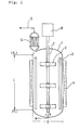
- Fig. 1 is a schematic view exemplifying a polymerization apparatus used in the present invention.
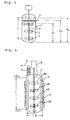
- Fig. 2 is a schematic view exemplifying a stirring impeller used in the present invention.
- Fig. 3 is a view illustrating the position of arrangement of the uppermost stirring impeller used in the present invention.
- Fig. 4 is a schematic view of other polymerization apparatus used in the present invention.
- the polymerization vessel to which the production process of the present invention is applied is basically a generally cylindrical polymerization vessel 1 constructed of a cylindrical straight barrel, a generally semispherical top part and a generally semispherical bottom part, which parts close respectively the top and the bottom of the cylindrical straight barrel, as shown in Fig. 1.
- the inner volume of the polymerization vessel 1 is 100 m 3 or more, and preferably 100 to 200 m 3
- the ratio L/D of the length L of the straight barrel to the inner diameter D of the polymerization vessel is 1.5 or more, and preferably 1.5 to 2.5.
- a plurality, preferably 3 or more, more preferably 3 to 5, of the stirring impellers used in the present invention are arranged along a rotating shaft 7 arranged on the center line A of the polymerization vessel 1 and the uppermost stirring impeller 2 is arranged, for example, as shown in Fig. 2, in the range of 150 to 300 cm downwardly on the basis of the upper end position TL of the straight barrel of the polymerization vessel 1 in terms of the height of the center line C of the vertical width w of the impeller blade of the uppermost stirring impeller.
- the materials to be charged into the polymerization vessel are charged such that both the relations: 10 9 H 1 ⁇ H 0 ⁇ 100 65 H 1 and H 0 ⁇ H 2 , wherein H 0 denotes the height of the liquid surface of the contents that have not yet been reacted, H 1 has the same meaning as defined above, and H 2 denotes the height of the upper end of the straight barrel, are simultaneously satisfied.
- a known stirring impeller can be used, and, for example, a paddle impeller, a pitched paddle impeller, a Brumagin type impeller, a Pfaudler impeller, a turbine impeller, and a propeller impeller can be used.
- paddle impellers each having a plurality of plate-like and generally rectangular impeller blades 4 radially arranged around the rotating shaft B as shown in Fig. 2.
- the number of the impeller blades 4 is generally 2 to 6, and preferably 2.
- the size of the blade 4 is not particularly restricted so long as it does not affect the rotation, but preferably the size satisfies the following relations: 0.35 ⁇ d/D ⁇ 0.55, and 0.10 ⁇ n ⁇ w/D ⁇ 0.16 wherein D have the same meaning as defined above, d denotes an impeller diameter as shown in Fig. 2, w denotes a vertical width of the impeller blade 4, and n is the number of the paddle impellers 2.
- a combination of these paddle impellers with other stirring impellers is also preferable, and an example is a combination of paddle impellers 2a, 2c with pitched paddle impellers 2b, 2d (the angle of inclination of the blade of the pitched paddle impellers is, for example, 45 degrees with the rotating shaft B).
- the positional relationship of the paddle impellers with the other stirring impellers is not particularly restricted and may be appropriately decided so that the mixing of the contents may be carried out uniformly.
- Such stirring impellers 2 are fixed to a rotating shaft 7 and the rotating shaft 7 is driven by an electric motor 8 placed at the upper part or the lower part of the polymerization vessel 1.
- the impeller speed in r.p.m. by the electric motor 8 is preferably such that the speed of the forward end of the stirring impeller 2 will fall in the range of 7 to 15 m/s.
- the driving force (stirring power of the stirring impeller) of the electric motor 8 is preferably 80 to 170 kg ⁇ m/s per ton of the contents in the polymerization vessel 1.
- Examples of the reflux condenser used in the present invention include a directly connected type condenser which is arranged, as shown in Fig. 1, at the upper part of the polymerization vessel 1, condenses monomer vapor generated in the polymerization vessel 1 through one conduit provided at the lower end of the condenser, and allows the resulting condensate to flow back into the polymerization vessel 1 through the same conduit, and a separate type condenser, as shown in Fig. 4, which condenses monomer vapor generated in the polymerization vessel 1 through the side conduit among two conduits provided at the lower end of the condenser and allows the condensed monomer to flow back into the polymerization vessel 1 through the central conduit.
- a directly connected type condenser which is arranged, as shown in Fig. 1, at the upper part of the polymerization vessel 1, condenses monomer vapor generated in the polymerization vessel 1 through one conduit provided at the lower end of the condenser, and allows the resulting condensate to flow back into the poly
- a known reflux condenser which has such a structure that the reflux condenser is connected to the polymerization vessel itself through one or more conduits through which the vapor and the condensate flows, and examples include a coil type reflux condenser, a spiral type reflux condenser, a multi-tubular type reflux condenser, and a shell-and-tube type reflux condenser, with preference being given to a shell-and-tube type reflux condenser inter alia.
- the heat transfer area of the reflux condenser is preferably 60 to 300 m 2 .
- Reference numeral 9 indicates a discharge outlet for noncondensable gases.
- the evacuation of noncondensable gases in the reflux condenser is started and the cooling by the reflux condenser is started.
- the polymerization temperature may be any polymerization temperatures known in suspension polymerization of vinyl monomers and is generally 35 to 60°C.
- the time when the evacuation of noncondensable gases is carried out is after the temperature of the polymerization vessel was elevated to near the polymerization temperature, and generally after the temperature of the polymerization vessel reached(t - 5)°C to t°C, and preferably (t - 2)°C to t°C, wherein t denotes the polymerization temperature. If the evacuation is carried out prematurely, foaming occurs in the polymerization vessel, and the foam containing the polymerization initiator goes concomitantly into the gaseous phase part and the condenser, causing the formation of scale to increase and the resulting foamed polymer to contaminate the intended polymer, which sometimes leads to the formation of fish eyes in the vinyl chloride polymer product obtained from that polymer.
- the elevation of the temperature is carried out by passing hot water or steam through a heating and cooling jacket 5 arranged around the polymerization vessel 1 as shown in Fig. 1 for heating and cooling the contents in the polymerization vessel 1.
- the elevation to the above temperature range causes noncondensable gases dissolved in the contents of the polymerization vessel to evaporate from the liquid phase and them to accumulate in the gaseous phase part. Since the noncondensable gases are smaller in specific gravity than vinyl chloride monomer, they are concentrated in the gaseous phase part of the polymerization vessel and in the reflux condenser.
- the way of evacuating the noncondensable gases is not particularly restricted and an example is a method wherein the evacuation is carried out through a discharge outlet provided at the top of the reflux condenser 6 by, for example, a pump (not shown).
- the flow rate of the noncondensable gases evacuated from the reflux condenser is 10 to 100 Nm 3 /hour, and preferably 10 to 60 Nm 3 /hour. If the flow rate is less than 10 Nm 3 /hour, since it is difficult to keep constant the quantity of heat dissipation by the reflux condenser for each batch, it becomes difficult to control the polymerization temperature invariably, scale is apt to be deposited at the interface part in the polymerization vessel, and fish eyes in the resulting vinyl chloride polymer are increased.
- the evacuation of noncondensable gases is continuously carried out for a period equal to 20 % or more, preferably 20 to 80 %, and more preferably 20 to 60 % or more, of the total polymerization time. If the evacuation time is less than 20 % based on the total polymerization time, since it is difficult to keep constant the quantity of heat dissipation by the reflux condenser, it becomes difficult to control the polymerization temperature invariably, scale is apt to be deposited at the interface in the polymerization vessel, and fish eyes in the resulting vinyl chloride polymer are increased.
- a method of controlling the quantity of heat dissipation by a reflux condenser for example, a method wherein the temperature and the flow rate of cooling water are controlled (see Japanese Pre-examination Patent Publication (KOKAI) No. 57-8206) may be used, and specifically it is preferable to control the quantity of heat dissipation suitably in the range of 2.1 x 10 6 to 8.4 x 10 6 kJ/h.
- the polymerization apparatus used in the production process of the present invention may be provided with, in addition to the above polymerization vessel, stirring impellers, reflux condenser, and heating and cooling jacket, baffles 3 as shown in Fig. 1.
- any known suitable baffles can be used, and, for example, one to eight baffles in the shape of a flat plate or a pipe are placed vertically along the inner wall of the polymerization vessel in position.
- vinyl chloride not only vinyl chloride can be used singly, but also a monomer mixture made up of vinyl monomer as a major constituent and a comonomer copolymerizable with vinyl chloride (generally the monomer mixture contains 50 % by weight or more of vinyl chloride) can be used.
- a comonomer includes vinyl esters, such as vinyl acetate and vinyl propionate; acrylic esters or methacrylic esters, such as methyl acrylate and ethyl acrylate; olefins, such as ethylene and propylene; maleic anhydride; acrylonitrile; styrene; ⁇ -methylstyrene; and vinylidene chloride. These may be used singly or as a combination of two or more thereof.
- the amount of an aqueous medium (water) charged for use in suspending and dispersing polymerized components of the monomer may be similar to that in the conventional method, that is, the charge ratio (water/monomer) of the water to the monomer may be from 1.0 to 1.5 (by weight), and, if desired, water can be added in the course of the polymerization.
- polyvinyl alcohol for example, polyvinyl alcohol; water-soluble and oil-soluble methyl cellulose and ethyl cellulose; water-soluble cellulose ethers, such as hydroxyethyl cellulose, hydroxypropyl cellulose, and hydroxypropyl methyl cellulose; water-soluble polymers, such as polyacrylic acid and gelatin; oil-soluble emulsifiers, such as sorbitan monolaurate, sorbitan trioleate, sorbitan monostearate, glycerin tristearate, and an ethylene oxide/propylene oxide block copolymer; water-soluble emulsifiers, such as polyoxyethylene sorbitan monolaurate, polyoxyethylene glycerin oleate, and sodium laurate; calcium carbonate, calcium phosphate, or sodium dodecylbenzenesulfonate may be used in a small amount in the range where the objects of the present invention
- the amount of these suspending agents to be added is 0.01 to 5 parts by weight per 100 parts by weight of the charge monomer.
- the oil-soluble polymerization initiator used in the present invention can include, for example, percarbonate compounds, such as diisopropyl peroxydicarbonate, di-2-ethylhexyl peroxydicarbonate, and diethoxyethyl peroxydicarbonate; perester compounds, such as t-butyl peroxypivalate, t-hexyl peroxypivalate, t-butyl peroxyneodecanoate, and ⁇ -cumyl peroxyneodecanoate; peroxides, such as acetylcyclohexylsulfonyl peroxide, 2,4,4-trimethylpentyl-2-peroxyphenoxyacetate, and 3,5,5-trimethylhexanoyl peroxide; and azo compounds, such as azobis-2,4-dimethylvaleronitrile and azobis(4-methoxy-2,4-dimethylvaleronitrile), which may be used singly or
- the amount of these oil-soluble polymerization initiators to be added is generally 0.01 to 3 parts by weight per 100 parts by weight of the monomer charged.
- aqueous medium deionized water is generally used.
- a polymerization adjuster if desired, a chain transfer agent, a pH adjuster, a gelation improver, an antistatic agent, a crosslinking agent, a stabilizer, a filler, an antioxidant, a buffer, and the like which are suitably used in vinyl chloride type polymerization may be optionally added.
- a scale deposition preventive agent may be previously applied to the polymerization vessel inner wall.
- any known scale deposition preventive agents can be used, such as, a self-condensation product of polyhydric phenols and polyhydric naphthols (Japanese Pre-examination Patent Publication (KOKAI) No. 54-7487); a condensation product of 1-naphthol and formaldehyde (Japanese Pre-examination Patent Publication (KOKAI) No. 57-164107); a condensation product of phenol compounds with aldehydes (Japanese Pre-examination Patent Publication (KOKAI) No.
- other conditions in the polymerization and the method of charging an aqueous medium, vinyl chloride monomer, and, in some cases, other comonomer, a suspending agent and a polymerization initiator into the polymerization vessel may be the same as the conventional conditions and method, and although the conditions of charging them may be the same as the conventional conditions, generally, they are charged such that 80 to 90 %, and preferably 82 to 87 %, of the volume of the polymerization vessel is filled with them. Such a charge brings the liquid surface almost near to the upper end position TL of the straight barrel of the polymerization vessel in the state of the above stirring impellers being rotated.
- a polymerization apparatus as shown in Fig. 1 which was equipped with (a) a generally cylindrical polymerization vessel 1 constructed of a cylindrical straight barrel, a semispherical top part and a semispherical bottom part, which parts closed the top and the bottom thereof respectively, and having an internal volume of 130 m 3 with the ratio L/D of the length (L: 7,900 mm) of the straight barrel to the inner diameter (D: 4,200 mm) being 1.88, (b) a heating and cooling jacket 5, (c) three stirring impellers 2, each having impeller blades, comprising paddle impellers arranged along a rotating shaft 7 (the uppermost stirring impeller was placed at 250 cm downwardly from the upper end position TL of the straight barrel of the polymerization vessel in terms of the height of the center line C of the vertical width of the impeller blade of the same stirring impeller), (d) baffles 3, and (e) a reflux condenser (of shell-and-tube type and having a heat transfer area of 150 m 2
- the stirring power (the driving power of the electric motor) was 130 kg/s per weight ton of the contents of the polymerization vessel.
- the liquid surface H 0 of the contents of the polymerization vessel at rest was 853 cm.
- the height H 1 of the upper edge of the uppermost stirring impeller was 655 cm, and the height H 2 of the upper end of the straight barrel was 895 cm, both the relations: 10 9 H 1 ⁇ H 0 ⁇ 100 65 H 1 and H 0 ⁇ H 2 , being satisfied simultaneously, and H 1 being 1.56D.
- Example 1 The polymerization of Example 1 was repeated, except that the evacuation of noncondensable gases was carried out for 45 min after the temperature was elevated to the polymerization temperature. Since the quantity of heat dissipation by the reflux condenser during the polymerization did not reach the predetermined 5,4 x 10 6 kJ/hour, the temperature of the contents of the polymerization vessel was increased by 1.5°C from the predetermined temperature of 57°C. The obtained polymer was tested similarly to Example 1. The results are shown in Table 1. The relations of H 1 , H 0 , H 2 ,and D were the same as those in Example 1.
- Example 1 The polymerization of Example 1 was repeated, except that the evacuation flow rate of noncondensable gases was set at 150 Nm 3 /hour. The obtained polymer was tested similarly to Example 1. The results are shown in Table 1. The relations of H 1 , H 0 , H 2 , and D were the same as those in Example 1.
- Example 1 The polymerization of Example 1 was repeated, except that the evacuation flow rate of noncondensable gases was set at 5 Nm 3 /hour. Since the quantity of heat dissipation by the reflux condenser during the polymerization did not reach the predetermined 5,4 x 10 6 kJ/hour, the temperature of the contents of the polymerization vessel was increased by 1.5°C from the predetermined temperature of 57°C. The obtained polymer was tested similarly to Example 1. The results are shown in Table 1. The relations of H 1 , H 0 , H 2 , and D were the same as those in Example 1.
- Example 1 The polymerization of Example 1 was repeated, except that the position of the uppermost stirring impeller was changed such that the position was at 100 mm downwardly from the upper end position TL of the straight barrel of the polymerization vessel.
- the obtained polymer was tested similarly to Example 1. The results are shown in Table 1.
- H 1 was 805 cm, not satisfying simultaneously the relations: 10 9 H 1 ⁇ H 0 ⁇ 100 65 H 1 and H 0 ⁇ H 2 , and H 1 being 1.92D.
- Example 1 The polymerization of Example 1 was repeated, except that the position of the uppermost stirring impeller was changed such that the position was at 400 mm downwardly from the upper end position TL of the straight barrel of the polymerization vessel.
- the obtained polymer was tested similarly to Example 1. The results are shown in Table 1.
- H 1 was 505 cm, not satisfying simultaneously the relations: 10 9 H 1 ⁇ H 0 ⁇ 100 65 H 1 and H 0 ⁇ H 2 , and H 1 being 1.20D.
- a polymerization apparatus as shown in Fig. 1 that was equipped with (a) a generally cylindrical polymerization vessel 1 constructed of a cylindrical straight barrel, a semispherical top part and a semispherical bottom part, which parts closed the top and the bottom thereof respectively, and having an internal volume of 100 m 3 with the ratio L/D of the length (L: 7,240 mm) of the straight barrel to the inner diameter (D: 3,850 mm) being 1.88, (b) a heating and cooling jacket 5, (c) three stirring impellers 2, each having impeller blades, comprising paddle impellers arranged along a rotating shaft 7 (the uppermost stirring blade was placed at 240 cm downwardly from the upper end position TL of the straight barrel of the polymerization vessel in terms of the height of the center line C of the vertical width of the impeller blade of the same stirring impeller), (d) baffles 3, and (e) a reflux condenser (of shell-and-tube type and having a heat transfer area of 120 m 2
- the stirring power (the driving power of the electric motor) was 130 kg/s per weight ton of the contents of the polymerization vessel.
- the liquid surface H 0 of the contents of the polymerization vessel was 782 cm.
- the height H 1 of the upper edge of the uppermost stirring blade was 590 cm, and the height H 2 of the upper end of the straight barrel was 820 cm, satisfying simultaneously the relations: 10 9 H 1 ⁇ H 0 ⁇ 100 65 H 1 and H 0 ⁇ H 2 , and H 1 being 1.53D.
- a polymerization apparatus as shown in Fig. 4 that was equipped with (a) a generally cylindrical polymerization vessel 1 constructed of a cylindrical straight barrel, a semispherical top part and a semispherical bottom part, which parts closed the top and the bottom thereof respectively, and having an internal volume of 100 m 3 with the ratio L/D of the length (L: 7,240 mm) of the straight barrel to the inner diameter (D: 3,850 mm) being 1.88, (b) a heating and cooling jacket 5, (c) four stirring impellers 2, each having impeller blades, comprising paddle impellers arranged along a rotating shaft 7 (the uppermost stirring impeller was placed at 240 cm downwardly from the upper end position TL of the straight barrel of the polymerization vessel in terms of the height of the center line C of the vertical width of the impeller blade of the same stirring impeller), (d) baffles 3, and (e) a reflux condenser 6 (of shell-and-tube type and having a heat transfer area of 120 m
- Example 2 Then the polymerization reaction in Example 2 was repeated, except that the above polymerization apparatus was used.
- the obtained polymer in the state of slurry was removed outside of the polymerization vessel, the state of the deposition of scale in the polymerization vessel was observed, and the obtained polymer was dehydrated and dried and was tested in accordance with the same methods as those in Example 1. The results are shown in Table 2.
- Example 2 Example 3 Evacuation flow rate of noncondensable gases 40 Nm 3 /hour 40 Nm 3 /hour Evacuation time of noncondensable gases 3 hours after the temperature was elevated to the polymerization temperature 3 hours after the temperature was elevated to the polymerization temperature Quantity of heat dissipation by the reflux condenser 4.2 x 10 6 kJ/hour from the start of the polymerization 4.2 x 10 6 kJ/hour from the start of the polymerization Polymerization time 5 hours and 10 min 5 hours and 10 min Bulk specific gravity 0.526 0.529 Particle size distribution #60 100 100 #100 62.3 68.9 #200 1.0 1.0 Fish eyes 1 2 Deposition of scale little deposition little deposition Uppermost impeller position (downwardly from the upper TL position) at 240 cm in the apparatus shown in Fig. 1 at 240 cm in the apparatus shown in Fig. 4
Landscapes
- Chemical & Material Sciences (AREA)
- Chemical Kinetics & Catalysis (AREA)
- Organic Chemistry (AREA)
- Health & Medical Sciences (AREA)
- Medicinal Chemistry (AREA)
- Polymers & Plastics (AREA)
- Polymerisation Methods In General (AREA)
- Addition Polymer Or Copolymer, Post-Treatments, Or Chemical Modifications (AREA)
Claims (9)
- Procédé pour préparer un polymère du type du chlorure de vinyle, comprenant la polymérisation en suspension d'un monomère de chlorure de vinyle ou d'un mélange de monomères vinyliques constitué principalement d'un monomère de chlorure de vinyle, dans un milieu aqueux, en présence d'un initiateur de la polymérisation soluble dans l'huile, dans un appareil de polymérisation qui comprend(a) un récipient de polymérisation généralement cylindrique comprenant un cylindre droit, une partie supérieure de forme généralement hémisphérique et une partie inférieure de forme généralement hémisphérique, lesdites parties obturant le sommet et le fond du cylindre droit, respectivement,(b) des roues d'agitation comprenant chacune des ailettes, disposées en étages le long d'un arbre rotatif arrangé sur la médiane dudit récipient de polymérisation,(c) un condenseur à reflux arrangé dans la partie supérieure dudit récipient de polymérisation pour condenser des vapeurs de monomères générées dans ledit récipient de polymérisation et pour refluer le condensat résultant dans ledit récipient de polymérisation, et(d) une enveloppe de chauffage et de refroidissement arrangée autour dudit récipient de polymérisation pour chauffer et refroidir le contenu liquide dudit récipient de polymérisation tout en agitant ledit monomère de chlorure de vinyle ou ledit mélange de monomères vinyliques à l'aide desdites roues d'agitation et tout en évacuant les gaz non condensables évaporés dudit contenu,dans lequel le volume interne du récipient de polymérisation représente 100 m3 ou plus, le rapport UD de la longueur L du cylindre droit au diamètre interne D du récipient de polymérisation s'élève à 1,5 ou plus, et on arrange la roue d'agitation située le plus en haut de telle sorte que la hauteur de la médiane de la largeur verticale de son ailette se situe dans le domaine de 150 à 300 cm en aval par rapport à la position terminale supérieure TL du cylindre droit du récipient de polymérisation, dans lequel les matières qui doivent être chargées dans le récipient de polymérisation sont chargées de telle sorte que l'on satisfait simultanément aux deux équations ci-après:

dans lequel, après avoir chauffé le contenu du récipient de polymérisation jusqu'à une température de polymérisation visée ou jusqu'à une température proche de ladite température de polymérisation, on évacue les gaz non condensables pénétrant dans le condenseur à reflux dans des conditions telles que l'on obtient un débit d'évacuation de 10 à 100 Nm3/heure et que le temps d'évacuation est égal à une période représentant 20% ou plus du temps de polymérisation total, le refroidissement via le condenseur à reflux étant déclenché simultanément à l'évacuation des gaz non condensables ou après le début de cette évacuation. - Procédé selon la revendication 1, dans lequel le volume interne du récipient de polymérisation est de 100 à 200 m3.
- Procédé selon la revendication 1, dans lequel le rapport L/D de la longueur L du cylindre droit au diamètre interne est de 1,5 à 2,5.
- Procédé selon la revendication 1, dans lequel le nombre d'étages des roues d'agitation est de 3 à 5.
- Procédé selon la revendication 1, dans lequel la roue d'agitation située le plus en haut est arrangée de telle sorte que l'on obtient un domaine, en ce qui concerne H1, de 1,3D à 1,85D, où H1 désigne la hauteur du bord supérieur des ailettes de la même roue d'agitation et D a la même signification que celle définie à la revendication 1.
- Procédé selon la revendication 1, dans lequel les roues d'agitation sont des roues à ailettes comprenant chacune plusieurs ailettes généralement rectangulaires arrangées en direction radiale autour de l'arbre rotatif ou encore une combinaison desdites roues à ailettes avec d'autres roues à ailettes.
- Procédé selon la revendication 1, dans lequel la puissance d'agitation des roues d'agitation est de 80 à 170 kg.m/s par tonne en poids du contenu du récipient de polymérisation.
- Procédé selon la revendication 1, dans lequel la température de polymérisation est de 35 à 60°C.
- Procédé selon la revendication 1, dans lequel le rapport pondéral du milieu aqueux au monomère ou au mélange de monomères est de 1,0 à 1,5 et la quantité de l'initiateur de la polymérisation soluble dans l'huile est de 0,01 à 3 parties en poids par 100 parties en poids du monomère ou du mélange de monomères.
Applications Claiming Priority (2)
| Application Number | Priority Date | Filing Date | Title |
|---|---|---|---|
| JP247104/94 | 1994-09-14 | ||
| JP24710494 | 1994-09-14 |
Publications (2)
| Publication Number | Publication Date |
|---|---|
| EP0702033A1 EP0702033A1 (fr) | 1996-03-20 |
| EP0702033B1 true EP0702033B1 (fr) | 1997-12-03 |
Family
ID=17158495
Family Applications (1)
| Application Number | Title | Priority Date | Filing Date |
|---|---|---|---|
| EP95114399A Expired - Lifetime EP0702033B1 (fr) | 1994-09-14 | 1995-09-13 | Procédé de préparation d'un polymère de type chlorure de vinyle |
Country Status (3)
| Country | Link |
|---|---|
| US (1) | US5587437A (fr) |
| EP (1) | EP0702033B1 (fr) |
| DE (1) | DE69501137T2 (fr) |
Families Citing this family (11)
| Publication number | Priority date | Publication date | Assignee | Title |
|---|---|---|---|---|
| DE19711022A1 (de) * | 1997-03-17 | 1998-09-24 | Basf Ag | Verwendung eines Mehrstufenrührers zur Herstellung von Polymerisaten |
| FR2796311B1 (fr) * | 1999-07-16 | 2001-09-14 | Atofina | Reacteur multietage, ses applications et procede de fabrication du peroxyde d'hydrogene |
| US6521721B1 (en) * | 1999-10-28 | 2003-02-18 | Nippon Shokubai Co., Ltd | Polymer production process |
| JP2003246808A (ja) * | 2002-02-26 | 2003-09-05 | Shin Etsu Chem Co Ltd | 塩化ビニル系重合体の製造方法 |
| US6702917B1 (en) | 2002-08-30 | 2004-03-09 | Kimberly-Clark Worldwide, Inc. | Cross-machine-direction nested absorbent pads with minimal waste geometries |
| JP5566295B2 (ja) * | 2008-09-18 | 2014-08-06 | 東洋エンジニアリング株式会社 | 重合樹脂の製造装置、重合容器及び製造方法 |
| CA2960005C (fr) * | 2014-09-04 | 2023-02-14 | Kuraray Co., Ltd. | Procede destine a produire un polymere anionique |
| CN108246224A (zh) * | 2018-02-01 | 2018-07-06 | 重庆金茂达特种橡胶有限公司 | 反应釜温控装置及其温控方法 |
| JP7291551B2 (ja) * | 2019-06-19 | 2023-06-15 | 信越化学工業株式会社 | 塩化ビニル系重合体の製造方法 |
| CN112108097B (zh) * | 2020-09-10 | 2022-05-24 | 军事科学院系统工程研究院军需工程技术研究所 | 一种新型管式增粘设备 |
| CN112569887A (zh) * | 2020-12-01 | 2021-03-30 | 郑现才 | 一种大豆磷脂溶剂脱脂回收装置 |
Family Cites Families (19)
| Publication number | Priority date | Publication date | Assignee | Title |
|---|---|---|---|---|
| BE670325A (fr) * | 1965-09-30 | 1966-01-17 | ||
| US4024330A (en) | 1975-04-08 | 1977-05-17 | The B. F. Goodrich Company | Internally coated reaction vessel and process for coating the same |
| DE2625149C3 (de) * | 1976-06-04 | 1981-01-08 | Hoechst Ag, 6000 Frankfurt | Verfahren und Vorrichtung zur kontinuierlichen Herstellung von Vinylchloridpolymerisaten in wäßriger Emulsion |
| JPS5436389A (en) | 1977-08-26 | 1979-03-17 | Kanegafuchi Chem Ind Co Ltd | Polymerization of vinyl chloride |
| US4080173A (en) | 1977-06-20 | 1978-03-21 | The B. F. Goodrich Company | Internally coated reaction vessel for use in olefinic polymerization |
| JPS578206A (en) | 1980-06-17 | 1982-01-16 | Shin Etsu Chem Co Ltd | Suspension polymerization of vinyl chloride type monomer |
| DE3175656D1 (en) | 1980-10-31 | 1987-01-15 | Ici Plc | Vinyl chloride polymerisation process |
| US4567436A (en) | 1982-01-21 | 1986-01-28 | Linda Koch | Magnetic thickness gauge with adjustable probe |
| IN165525B (fr) | 1984-07-23 | 1989-11-04 | Shinetsu Chemical Co | |
| JPS6136301A (ja) * | 1984-07-27 | 1986-02-21 | Kanegafuchi Chem Ind Co Ltd | 重合反応缶内の温度制御方法 |
| JPH0617363B2 (ja) | 1986-04-08 | 1994-03-09 | 東ソー株式会社 | ビニル系単量体の重合法 |
| JPH0625203B2 (ja) | 1987-11-19 | 1994-04-06 | 鐘淵化学工業株式会社 | 重合体スケールの付着防止方法 |
| EP0496816A4 (en) | 1989-04-27 | 1992-10-28 | Occidental Chemical Corporation | Polymerization reactor scale prevention |
| IT1235098B (it) | 1989-06-15 | 1992-06-18 | Francesco Carlin | Procedimento per la produzione in emulsione acquosa di miscele di alcoli polivinilici e prodotti cosi' ottenuti. |
| JP3106583B2 (ja) | 1990-09-17 | 2000-11-06 | 三菱化学株式会社 | 塩化ビニル系単量体の重合方法 |
| DE4031547A1 (de) | 1990-10-05 | 1992-04-09 | Hell Rudolf Dr Ing Gmbh | Verfahren und vorrichtung zur herstellung von texturwalzen |
| JP2924259B2 (ja) | 1991-04-11 | 1999-07-26 | 住友化学工業株式会社 | ナフトール類のスルフィド化合物からなる重合器内部表面の付着防止剤及び該付着防止剤を用いたビニル系単量体の重合方法 |
| JP2836765B2 (ja) * | 1991-07-05 | 1998-12-14 | 信越化学工業株式会社 | 塩化ビニル系重合体の製造装置 |
| JPH05279404A (ja) | 1992-03-31 | 1993-10-26 | Kanegafuchi Chem Ind Co Ltd | スチレン系単量体の懸濁重合方法 |
-
1995
- 1995-09-13 DE DE69501137T patent/DE69501137T2/de not_active Expired - Lifetime
- 1995-09-13 EP EP95114399A patent/EP0702033B1/fr not_active Expired - Lifetime
- 1995-09-14 US US08/528,097 patent/US5587437A/en not_active Expired - Lifetime
Also Published As
| Publication number | Publication date |
|---|---|
| DE69501137D1 (de) | 1998-01-15 |
| DE69501137T2 (de) | 1998-04-09 |
| EP0702033A1 (fr) | 1996-03-20 |
| US5587437A (en) | 1996-12-24 |
Similar Documents
| Publication | Publication Date | Title |
|---|---|---|
| US5420215A (en) | Process for producing vinyl chloride-based polymer | |
| EP0702033B1 (fr) | Procédé de préparation d'un polymère de type chlorure de vinyle | |
| US4464517A (en) | Process for the suspension polymerization of vinyl chloride | |
| US5750079A (en) | Polymerization apparatus of producing vinyl chloride type polymer | |
| US7763690B2 (en) | Method for producing peroxydicarbonates and their use in the radical polymerization of monomers | |
| JP3388663B2 (ja) | 塩化ビニル系重合体の製造方法 | |
| WO2022265057A1 (fr) | Appareil de réaction, procédé de fabrication de polymère vinylique, et procédé de production de polymère vinylique | |
| US5763545A (en) | Polymerization apparatus and a method for producing polymer using the same | |
| US5610245A (en) | Polymerization method producing vinyl chloride polymer | |
| JP3197447B2 (ja) | 重合装置及びそれを用いる塩化ビニル系重合体の製造方法 | |
| US5357011A (en) | Process for producing vinyl chloride-based polymers | |
| JP3197445B2 (ja) | 重合装置及びそれを用いる塩化ビニル系重合体の製造方法 | |
| JP3691747B2 (ja) | 重合装置及びこれを用いた塩化ビニル系重合体の製造方法 | |
| JP2005281659A (ja) | 塩化ビニル系重合体の製造方法 | |
| JPH1135607A (ja) | 塩化ビニル系樹脂の製造方法 | |
| JP3568695B2 (ja) | 塩化ビニル系重合体の製造方法 | |
| JP2000017007A (ja) | 塩化ビニル系樹脂の製造方法 | |
| JP3568696B2 (ja) | 塩化ビニル系重合体の製造方法 | |
| JPH0525204A (ja) | 塩化ビニル系単量体の懸濁重合方法 | |
| JP2000119312A (ja) | 塩化ビニル系樹脂の製造方法 | |
| EP0682043A2 (fr) | Procédé pour la préparation des polymères de chlorure de vinyle | |
| JP2006111661A (ja) | リフラックスコンデンサー付設重合器並びにその重合器を用いた重合体の製造方法 | |
| JPH05301908A (ja) | 塩化ビニル単量体の懸濁重合方法 | |
| JP2000001505A (ja) | 塩化ビニル系樹脂の製造方法 | |
| JP2001247603A (ja) | 塩化ビニル系重合体の製造方法 |
Legal Events
| Date | Code | Title | Description |
|---|---|---|---|
| PUAI | Public reference made under article 153(3) epc to a published international application that has entered the european phase |
Free format text: ORIGINAL CODE: 0009012 |
|
| AK | Designated contracting states |
Kind code of ref document: A1 Designated state(s): DE FR GB NL PT |
|
| 17P | Request for examination filed |
Effective date: 19960604 |
|
| 17Q | First examination report despatched |
Effective date: 19960913 |
|
| GRAG | Despatch of communication of intention to grant |
Free format text: ORIGINAL CODE: EPIDOS AGRA |
|
| GRAH | Despatch of communication of intention to grant a patent |
Free format text: ORIGINAL CODE: EPIDOS IGRA |
|
| GRAH | Despatch of communication of intention to grant a patent |
Free format text: ORIGINAL CODE: EPIDOS IGRA |
|
| GRAA | (expected) grant |
Free format text: ORIGINAL CODE: 0009210 |
|
| AK | Designated contracting states |
Kind code of ref document: B1 Designated state(s): DE FR GB NL PT |
|
| REF | Corresponds to: |
Ref document number: 69501137 Country of ref document: DE Date of ref document: 19980115 |
|
| ET | Fr: translation filed | ||
| REG | Reference to a national code |
Ref country code: PT Ref legal event code: SC4A Free format text: AVAILABILITY OF NATIONAL TRANSLATION Effective date: 19971215 |
|
| PLBE | No opposition filed within time limit |
Free format text: ORIGINAL CODE: 0009261 |
|
| STAA | Information on the status of an ep patent application or granted ep patent |
Free format text: STATUS: NO OPPOSITION FILED WITHIN TIME LIMIT |
|
| 26N | No opposition filed | ||
| REG | Reference to a national code |
Ref country code: GB Ref legal event code: IF02 |
|
| PGFP | Annual fee paid to national office [announced via postgrant information from national office to epo] |
Ref country code: FR Payment date: 20100921 Year of fee payment: 16 |
|
| PGFP | Annual fee paid to national office [announced via postgrant information from national office to epo] |
Ref country code: GB Payment date: 20100908 Year of fee payment: 16 |
|
| PGFP | Annual fee paid to national office [announced via postgrant information from national office to epo] |
Ref country code: PT Payment date: 20100907 Year of fee payment: 16 Ref country code: NL Payment date: 20100916 Year of fee payment: 16 |
|
| PGFP | Annual fee paid to national office [announced via postgrant information from national office to epo] |
Ref country code: DE Payment date: 20100908 Year of fee payment: 16 |
|
| REG | Reference to a national code |
Ref country code: PT Ref legal event code: MM4A Free format text: LAPSE DUE TO NON-PAYMENT OF FEES Effective date: 20120313 |
|
| REG | Reference to a national code |
Ref country code: NL Ref legal event code: V1 Effective date: 20120401 |
|
| GBPC | Gb: european patent ceased through non-payment of renewal fee |
Effective date: 20110913 |
|
| PG25 | Lapsed in a contracting state [announced via postgrant information from national office to epo] |
Ref country code: PT Free format text: LAPSE BECAUSE OF NON-PAYMENT OF DUE FEES Effective date: 20120313 |
|
| REG | Reference to a national code |
Ref country code: FR Ref legal event code: ST Effective date: 20120531 |
|
| REG | Reference to a national code |
Ref country code: DE Ref legal event code: R119 Ref document number: 69501137 Country of ref document: DE Effective date: 20120403 |
|
| PG25 | Lapsed in a contracting state [announced via postgrant information from national office to epo] |
Ref country code: DE Free format text: LAPSE BECAUSE OF NON-PAYMENT OF DUE FEES Effective date: 20120403 Ref country code: NL Free format text: LAPSE BECAUSE OF NON-PAYMENT OF DUE FEES Effective date: 20120401 |
|
| PG25 | Lapsed in a contracting state [announced via postgrant information from national office to epo] |
Ref country code: GB Free format text: LAPSE BECAUSE OF NON-PAYMENT OF DUE FEES Effective date: 20110913 Ref country code: FR Free format text: LAPSE BECAUSE OF NON-PAYMENT OF DUE FEES Effective date: 20110930 |