EP0702109A2 - Procédé et dispositif d'application en continu d'une enduction sur un matériau en bande - Google Patents
Procédé et dispositif d'application en continu d'une enduction sur un matériau en bande Download PDFInfo
- Publication number
- EP0702109A2 EP0702109A2 EP95111729A EP95111729A EP0702109A2 EP 0702109 A2 EP0702109 A2 EP 0702109A2 EP 95111729 A EP95111729 A EP 95111729A EP 95111729 A EP95111729 A EP 95111729A EP 0702109 A2 EP0702109 A2 EP 0702109A2
- Authority
- EP
- European Patent Office
- Prior art keywords
- doctor
- material web
- doctor blade
- actuator
- doctor knife
- Prior art date
- Legal status (The legal status is an assumption and is not a legal conclusion. Google has not performed a legal analysis and makes no representation as to the accuracy of the status listed.)
- Ceased
Links
Images


Classifications
-
- D—TEXTILES; PAPER
- D21—PAPER-MAKING; PRODUCTION OF CELLULOSE
- D21H—PULP COMPOSITIONS; PREPARATION THEREOF NOT COVERED BY SUBCLASSES D21C OR D21D; IMPREGNATING OR COATING OF PAPER; TREATMENT OF FINISHED PAPER NOT COVERED BY CLASS B31 OR SUBCLASS D21G; PAPER NOT OTHERWISE PROVIDED FOR
- D21H25/00—After-treatment of paper not provided for in groups D21H17/00 - D21H23/00
- D21H25/08—Rearranging applied substances, e.g. metering, smoothing; Removing excess material
- D21H25/10—Rearranging applied substances, e.g. metering, smoothing; Removing excess material with blades
-
- B—PERFORMING OPERATIONS; TRANSPORTING
- B05—SPRAYING OR ATOMISING IN GENERAL; APPLYING FLUENT MATERIALS TO SURFACES, IN GENERAL
- B05C—APPARATUS FOR APPLYING FLUENT MATERIALS TO SURFACES, IN GENERAL
- B05C11/00—Component parts, details or accessories not specifically provided for in groups B05C1/00 - B05C9/00
- B05C11/02—Apparatus for spreading or distributing liquids or other fluent materials already applied to a surface ; Controlling means therefor; Control of the thickness of a coating by spreading or distributing liquids or other fluent materials already applied to the coated surface
- B05C11/04—Apparatus for spreading or distributing liquids or other fluent materials already applied to a surface ; Controlling means therefor; Control of the thickness of a coating by spreading or distributing liquids or other fluent materials already applied to the coated surface with blades
- B05C11/041—Apparatus for spreading or distributing liquids or other fluent materials already applied to a surface ; Controlling means therefor; Control of the thickness of a coating by spreading or distributing liquids or other fluent materials already applied to the coated surface with blades characterised by means for positioning, loading, or deforming the blades
Definitions
- the invention relates to a method for continuously applying a coating of constant thickness to a material web with an elastic doctor blade according to the preamble of claim 1.
- the invention further relates to an apparatus for performing the method.
- doctor knife also called a scraper or a blade
- deposits can build up between the coating knife and the material web due to impurities in the coating material, which lead to a strip-like coating pattern (doctor blade strip) which reduces the quality of the paper.
- a device for tensioning and prestressing an elastic doctor knife for coating systems wherein a structurally specially designed pressure medium hose is arranged on the side of the doctor knife facing the material web to adjust the prestressing force between the clamping device and the support bar. When pressurized, this presses the doctor blade away from the material web in the region between the clamping device and the support bar, so that the tip of the doctor blade located above the support bar is pressed toward the material web.
- This document also does not contain any information as to how squeegee strips forming in the coating can be avoided.
- the object of the present invention is to further develop a method of the type mentioned at the outset in such a way that the deposits which form between the doctor blade and the material web and then lead to doctor blades are prevented or eliminated in a simple and cost-effective manner.
- a device for performing this method is also to be disclosed.
- the invention is based on the idea of exciting the doctor blade to strong, low-frequency vibrations either at predetermined intervals or whenever there are doctor strips on the surface of the material web. As a result, the deposits between the doctor blade and the material web are crushed and rinsed out by the pressing coating.
- the oscillation frequency of the doctor knife should be between 1 and 5 Hz, preferably 2 Hz.
- a fluid e.g. Compressed air, fillable elastic element (actuator) used.
- the pressure of the fluid is changed periodically so that the corresponding surface of the actuator is periodically enlarged and the doctor blade is thereby also pressed periodically to the material web.
- an actuator that consists of a hose-like part that surrounds a metallic guide sleeve. At the ends of the guide sleeve, the hose is clamped between this sleeve and corresponding sleeve-like clamping elements surrounding the hose-like part.
- the compressed air supply for inflating the hose-like part takes place via the one clamping element having a cavity, which is connected to a pressure source via a pressure hose.
- the compressed air is then passed through the guide sleeve and a through opening in the outer wall of the guide sleeve into the space between the guide sleeve and the tubular part.
- the second clamping element is closed on the back, so that the compressed air cannot escape through this element.
- 1 denotes a doctor knife, which bears against a paper web 3 running over a counter-roller 2 with an excess of coating material 4 applied.
- the doctor blade 1 is clamped in the region of its first end 5 in a clamping device 8 consisting of a support beam 6 and clamping beam 7.
- a clamping device 8 consisting of a support beam 6 and clamping beam 7.
- the doctor blade 1 can be supported on the side facing away from the paper web 3 with a support bar 10.
- the support beam 6 has a recess 11 in which a filler 12 is located.
- an elastic element (actuator) 14 according to the invention, which can be filled with compressed air, is provided in a corresponding recess 13, which rests on the doctor blade 1 on the side facing away from the recess 13 of the filler 12. In the arrangement shown in FIG. 1, practically no prestressing forces are exerted by the actuator 14 on the doctor blade 1.
- a control device 16 activates a pressure control device 17 which acts on the actuator 14 with a periodically changing air pressure via a pressure hose 18.
- the actuator 14 is subjected to the maximum pressure. Since the actuator 14 cannot expand in the direction of the filler 12, it presses against the doctor knife 1, so that its contact area on the paper web 3 is substantially enlarged. An air gap 19 is formed between a support bar 10 and doctor blade 1 and impurities which are located between the front end 9 of the doctor blade 1 and the paper web 3 are crushed and washed out by the coating material 4. As soon as the air pressure drops, the actuator 14 shrinks and the front end 9 of the doctor blade 1 hits the support bar 10.
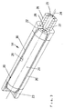
- FIG. 3 shows an embodiment of an actuator 14 according to the invention. It consists of a tubular part 20 (hereinafter also referred to as a tube), which surrounds a rigid (eg metallic) guide sleeve 21. At the ends of the guide sleeve 21, the hose 20 is between the guide sleeve 21 and corresponding sleeve-shaped clamping elements 22, 23 surrounding the hose 20 (for example metallic).
- a tubular part 20 hereinafter also referred to as a tube
- hose 20 is between the guide sleeve 21 and corresponding sleeve-shaped clamping elements 22, 23 surrounding the hose 20 (for example metallic).
- the compressed air supply for inflating the hose 20 takes place in the direction of the arrow 24 via the clamping element 22 which has a cavity 25 and which has a flange 26 for fastening the pressure hose 18 (FIG. 1).
- the compressed air then passes in the direction of arrow 27 into the interior 28 of the guide sleeve 21 and from there through an opening 29 in the outer wall 30 of the guide sleeve 21 into the exterior space located between the guide sleeve 21 and the hose 20.
- the second clamping element 23 is closed on the rear side, so that the compressed air cannot escape on this side of the actuator 14.
- the ends of the guide sleeve 21 and the corresponding inner walls of the tensioning elements 22, 23 are conical.
Landscapes
- Coating Apparatus (AREA)
- Application Of Or Painting With Fluid Materials (AREA)
Applications Claiming Priority (2)
| Application Number | Priority Date | Filing Date | Title |
|---|---|---|---|
| DE4433048 | 1994-09-16 | ||
| DE4433048A DE4433048A1 (de) | 1994-09-16 | 1994-09-16 | Verfahren und Vorrichtung zum kontinuierlichen Aufbringen einer Beschichtung auf eine Materialbahn |
Publications (2)
| Publication Number | Publication Date |
|---|---|
| EP0702109A2 true EP0702109A2 (fr) | 1996-03-20 |
| EP0702109A3 EP0702109A3 (fr) | 1997-05-07 |
Family
ID=6528406
Family Applications (1)
| Application Number | Title | Priority Date | Filing Date |
|---|---|---|---|
| EP95111729A Ceased EP0702109A3 (fr) | 1994-09-16 | 1995-07-26 | Procédé et dispositif d'application en continu d'une enduction sur un matériau en bande |
Country Status (5)
| Country | Link |
|---|---|
| US (2) | US5601868A (fr) |
| EP (1) | EP0702109A3 (fr) |
| JP (1) | JPH08108124A (fr) |
| DE (1) | DE4433048A1 (fr) |
| FI (1) | FI954317A7 (fr) |
Families Citing this family (42)
| Publication number | Priority date | Publication date | Assignee | Title |
|---|---|---|---|---|
| DE19627688A1 (de) * | 1996-07-10 | 1998-01-15 | Jagenberg Papiertech Gmbh | Dosiersystem für Vorrichtungen zum Beschichten von Materialbahnen, insbesondere Papier- oder Kartonbahnen |
| DE29617829U1 (de) * | 1996-10-14 | 1997-01-23 | Voith Sulzer Papiermaschinen GmbH, 89522 Heidenheim | Auftragseinrichtung zum Auftragen eines Streichmediums |
| DE19715345A1 (de) * | 1997-03-27 | 1998-10-01 | Voith Sulzer Papiermasch Gmbh | Verfahren zur Herstellung einer gestrichenen Warenbahn, insbesondere aus Papier oder Karton |
| DE19753899A1 (de) * | 1997-12-05 | 1999-06-10 | Jagenberg Papiertech Gmbh | Pneumatisch betätigbares Stellelement, insbesondere zur Regulierung des Querprofils in einer Beschichtungsvorrichtung für Papier- oder Kartonbahnen |
| DE19934441A1 (de) * | 1999-07-22 | 2001-01-25 | Voith Paper Patent Gmbh | Vorrichtung zum direkten oder indirekten Auftragen eines flüssigen oder pastösen Auftragsmediums auf eine laufende Materialbahn, insbesondere aus Papier oder Karton |
| ATE381398T1 (de) | 2000-09-25 | 2008-01-15 | Voxeljet Technology Gmbh | Verfahren zum herstellen eines bauteils in ablagerungstechnik |
| DE10049043A1 (de) * | 2000-10-04 | 2002-05-02 | Generis Gmbh | Verfahren zum Entpacken von in ungebundenem Partikelmaterial eingebetteten Formkörpern |
| DE10117875C1 (de) * | 2001-04-10 | 2003-01-30 | Generis Gmbh | Verfahren, Vorrichtung zum Auftragen von Fluiden sowie Verwendung einer solchen Vorrichtung |
| US6942904B2 (en) * | 2001-12-11 | 2005-09-13 | Ultra Technology Europe Ab | Dry end surface treatment using ultrasonic transducers |
| DE10216013B4 (de) * | 2002-04-11 | 2006-12-28 | Generis Gmbh | Verfahren und Vorrichtung zum Auftragen von Fluiden |
| DE10222167A1 (de) | 2002-05-20 | 2003-12-04 | Generis Gmbh | Vorrichtung zum Zuführen von Fluiden |
| DE10224981B4 (de) | 2002-06-05 | 2004-08-19 | Generis Gmbh | Verfahren zum schichtweisen Aufbau von Modellen |
| US7807077B2 (en) * | 2003-06-16 | 2010-10-05 | Voxeljet Technology Gmbh | Methods and systems for the manufacture of layered three-dimensional forms |
| DE10327272A1 (de) * | 2003-06-17 | 2005-03-03 | Generis Gmbh | Verfahren zum schichtweisen Aufbau von Modellen |
| DE102004008168B4 (de) | 2004-02-19 | 2015-12-10 | Voxeljet Ag | Verfahren und Vorrichtung zum Auftragen von Fluiden und Verwendung der Vorrichtung |
| DE102004029565A1 (de) * | 2004-06-18 | 2006-01-05 | Voith Paper Patent Gmbh | Rakelvorrichtung |
| KR100677677B1 (ko) * | 2004-12-15 | 2007-02-02 | 김종백 | 독터 블레이드 홀더 |
| US8312834B2 (en) * | 2005-04-14 | 2012-11-20 | Hamilton Sundstrand Corporation | Apparatus for applying thin coating |
| DE102005029613A1 (de) * | 2005-06-23 | 2007-01-04 | Voith Patent Gmbh | Vorrichtung zur Dosierung und/oder Egalisierung |
| DE102006038858A1 (de) * | 2006-08-20 | 2008-02-21 | Voxeljet Technology Gmbh | Selbstaushärtendes Material und Verfahren zum schichtweisen Aufbau von Modellen |
| DE102007050679A1 (de) * | 2007-10-21 | 2009-04-23 | Voxeljet Technology Gmbh | Verfahren und Vorrichtung zum Fördern von Partikelmaterial beim schichtweisen Aufbau von Modellen |
| DE102009030113A1 (de) | 2009-06-22 | 2010-12-23 | Voxeljet Technology Gmbh | Verfahren und Vorrichtung zum Zuführen von Fluiden beim schichtweisen Bauen von Modellen |
| DE102010014969A1 (de) | 2010-04-14 | 2011-10-20 | Voxeljet Technology Gmbh | Vorrichtung zum Herstellen dreidimensionaler Modelle |
| DE102010027071A1 (de) | 2010-07-13 | 2012-01-19 | Voxeljet Technology Gmbh | Vorrichtung zum Herstellen dreidimensionaler Modelle mittels Schichtauftragstechnik |
| DE102010056346A1 (de) | 2010-12-29 | 2012-07-05 | Technische Universität München | Verfahren zum schichtweisen Aufbau von Modellen |
| DE102011007957A1 (de) | 2011-01-05 | 2012-07-05 | Voxeljet Technology Gmbh | Vorrichtung und Verfahren zum Aufbauen eines Schichtenkörpers mit wenigstens einem das Baufeld begrenzenden und hinsichtlich seiner Lage einstellbaren Körper |
| ITBO20110708A1 (it) * | 2011-12-14 | 2013-06-15 | Marchesini Group Spa | Apparato per regolare il rilascio di compresse negli alveoli di un nastro termoformato |
| JPWO2014057568A1 (ja) | 2012-10-11 | 2016-08-25 | サンデンホールディングス株式会社 | ディスク状基材への摺動用塗料の塗布方法 |
| WO2021212110A1 (fr) | 2020-04-17 | 2021-10-21 | Eagle Engineered Solutions, Inc. | Appareil et système d'étalement de poudre |
| US11707883B2 (en) | 2020-11-20 | 2023-07-25 | General Electric Company | Foil interaction device for additive manufacturing |
| US11865780B2 (en) | 2021-02-26 | 2024-01-09 | General Electric Company | Accumalator assembly for additive manufacturing |
| US12589549B2 (en) | 2021-04-27 | 2026-03-31 | General Electric Company | Systems and methods for additive manufacturing |
| US11951679B2 (en) | 2021-06-16 | 2024-04-09 | General Electric Company | Additive manufacturing system |
| US11731367B2 (en) | 2021-06-23 | 2023-08-22 | General Electric Company | Drive system for additive manufacturing |
| US11958250B2 (en) | 2021-06-24 | 2024-04-16 | General Electric Company | Reclamation system for additive manufacturing |
| US11958249B2 (en) | 2021-06-24 | 2024-04-16 | General Electric Company | Reclamation system for additive manufacturing |
| US11826950B2 (en) | 2021-07-09 | 2023-11-28 | General Electric Company | Resin management system for additive manufacturing |
| US12370741B2 (en) | 2021-08-13 | 2025-07-29 | General Electric Company | Material deposition assembly for additive manufacturing |
| US12296535B2 (en) | 2021-08-24 | 2025-05-13 | General Electric Company | Attachment structure for additive manufacturing |
| US11813799B2 (en) | 2021-09-01 | 2023-11-14 | General Electric Company | Control systems and methods for additive manufacturing |
| EP4249216A1 (fr) | 2022-03-23 | 2023-09-27 | General Electric Company | Systèmes et procédés de fabrication additive |
| US12403654B2 (en) | 2022-09-30 | 2025-09-02 | General Electric Company | Systems and methods for additive manufacturing |
Citations (2)
| Publication number | Priority date | Publication date | Assignee | Title |
|---|---|---|---|---|
| US1566358A (en) | 1924-09-05 | 1925-12-22 | Vickerys 1920 Ltd | Doctor for paper machines |
| DE3313972C2 (fr) | 1983-04-18 | 1989-04-13 | Jagenberg Ag, 4000 Duesseldorf, De |
Family Cites Families (12)
| Publication number | Priority date | Publication date | Assignee | Title |
|---|---|---|---|---|
| DE1012582B (de) * | 1952-09-18 | 1957-07-25 | Heinrich Nicolaus G M B H | Verfahren zur Herstellung von gleichmaessigen UEberzuegen auf Traegerstoffbahnen und Vorrichtung zur Durchfuehrung des Verfahrens |
| US3066047A (en) * | 1958-12-22 | 1962-11-27 | Beloit Iron Works | Coating machine and method using a vibrating fountain with doctor |
| DE2012598A1 (de) * | 1970-03-17 | 1971-10-21 | Voith Gmbh J M | Glättschaber-Streicheinrichtung |
| DE2356737A1 (de) * | 1973-11-14 | 1975-05-15 | Jagenberg Werke Ag | Verfahren und vorrichtung zum regeln der auftragsstaerke beim beschichten laufender bahnen aus papier od. dgl. |
| DE2555669C3 (de) * | 1975-12-11 | 1984-10-18 | J.M. Voith Gmbh, 7920 Heidenheim | Vorrichtung zum Abstreifen überschüssiger Streichmasse |
| DE2825907B2 (de) * | 1978-06-13 | 1981-02-26 | Jagenberg-Werke Ag, 4000 Duesseldorf | Vorrichtung zum Aufbringen einer Beschichtung auf eine Materialbahn |
| FR2476165A2 (fr) * | 1979-03-14 | 1981-08-21 | Centre Tech Ind Papier | Procede et dispositif d'enduction en continu d'un element en feuille, notamment une bande de papier ou de carton |
| DE3017274C2 (de) * | 1980-05-06 | 1985-07-18 | Jagenberg-Werke AG, 4000 Düsseldorf | Vorrichtung zum Streichen von Papierbahnen |
| US4405661A (en) * | 1981-09-10 | 1983-09-20 | Beloit Corporation | Blade type fountain coater and method |
| DE3729621A1 (de) * | 1987-09-04 | 1989-03-16 | Jagenberg Ag | Vorrichtung zum beschichten einer um eine gegenwalze gefuehrten materialbahn |
| DE3940450A1 (de) * | 1989-12-07 | 1991-06-13 | Voith Gmbh J M | Rakeleinrichtung |
| US5242498A (en) * | 1992-08-04 | 1993-09-07 | The Kohler Coating Machinery Corporation | Adjustable blade coater |
-
1994
- 1994-09-16 DE DE4433048A patent/DE4433048A1/de not_active Withdrawn
-
1995
- 1995-07-26 EP EP95111729A patent/EP0702109A3/fr not_active Ceased
- 1995-09-01 JP JP7225585A patent/JPH08108124A/ja active Pending
- 1995-09-14 FI FI954317A patent/FI954317A7/fi not_active Application Discontinuation
- 1995-09-18 US US08/529,543 patent/US5601868A/en not_active Expired - Fee Related
-
1996
- 1996-10-03 US US08/725,546 patent/US5746833A/en not_active Expired - Fee Related
Patent Citations (2)
| Publication number | Priority date | Publication date | Assignee | Title |
|---|---|---|---|---|
| US1566358A (en) | 1924-09-05 | 1925-12-22 | Vickerys 1920 Ltd | Doctor for paper machines |
| DE3313972C2 (fr) | 1983-04-18 | 1989-04-13 | Jagenberg Ag, 4000 Duesseldorf, De |
Also Published As
| Publication number | Publication date |
|---|---|
| JPH08108124A (ja) | 1996-04-30 |
| US5746833A (en) | 1998-05-05 |
| US5601868A (en) | 1997-02-11 |
| FI954317A0 (fi) | 1995-09-14 |
| DE4433048A1 (de) | 1996-03-21 |
| FI954317L (fi) | 1996-03-17 |
| EP0702109A3 (fr) | 1997-05-07 |
| FI954317A7 (fi) | 1996-03-17 |
Similar Documents
| Publication | Publication Date | Title |
|---|---|---|
| EP0702109A2 (fr) | Procédé et dispositif d'application en continu d'une enduction sur un matériau en bande | |
| AT392602B (de) | Streicheinrichtung zur beschichtung laufender warenbahnen | |
| DE19506522B4 (de) | Verfahren und Vorrichtung zum Laserstrahlschneiden | |
| DE19726897C2 (de) | Verfahren zum Reinigen eines Transportbandes | |
| DE2554499A1 (de) | Verfahren zum erzeugen von stoerungen in einem tintenstrahl | |
| DE69108547T2 (de) | Elektroentladungs-Drahtschneidemaschine. | |
| CH652618A5 (de) | Vorrichtung zum regeln der auftragsstaerke beim beschichten laufender materialbahnen. | |
| DE2532796A1 (de) | Tropfenstrahl-aufzeichnungskopf | |
| DE7707983U1 (de) | Vorrichtung zur erzeugung von ultraschallwellen | |
| DE3927329A1 (de) | Vorrichtung zum beschichten einer um eine gegenwalze gefuehrten materialbahn | |
| DE2637840A1 (de) | Verfahren und vorrichtung zum bestreichen beider seiten einer sich bewegenden materialbahn, vorzugsweise einer papierbahn | |
| DE2257102A1 (de) | Verfahren zur beseitigung des vom farbwerk uebertragenen farbueberschusses auf tiefdruckzylindern mittels rakel | |
| DE2552952C3 (de) | Vorrichtung zum Erzeugen von Tröpfchen in einem Tintenstrahldrucker | |
| EP0714766B1 (fr) | Procédé pour fabriquer des matrices d'impression par stencil | |
| DE68910955T2 (de) | Wellenleiter-einrichtung für einen kontinuierlich arbeitenden tintenstrahldrucker. | |
| EP0411196B1 (fr) | Dispositif d'enduction | |
| EP0590165B1 (fr) | Buse électrostatique, en particulier pour injecter des matériaux fluides à haute viscosité | |
| DE2637827C2 (fr) | ||
| DE3440634A1 (de) | Einrichtung zur beidseitigen beschichtung laufender warenbahnen | |
| EP0818711B1 (fr) | Procédé et appareil pour la fabrication de plaques d'impression flexographiques | |
| DE19627322C1 (de) | Verfahren zum dosierten Aufbringen von Flüssigkeiten auf Materialbahnen | |
| DE19743520A1 (de) | Rakeleinrichtung für eine Vorrichtung zum Auftragen eines flüssigen bis pastösen Mediums auf einen sich vorbeibewegenden Untergrund | |
| DE3125434A1 (de) | Vorrichtung zum zufuehren von farbe an die druckplatte einer druckmaschine | |
| DE4208897A1 (de) | Auftragswerk zum beschichten von bahnen aus papier oder karton | |
| EP0804992A1 (fr) | Procédé et dispositif pour la mise en oeuvre de la pression de soudage lors du soudage continu à la molette |
Legal Events
| Date | Code | Title | Description |
|---|---|---|---|
| PUAI | Public reference made under article 153(3) epc to a published international application that has entered the european phase |
Free format text: ORIGINAL CODE: 0009012 |
|
| AK | Designated contracting states |
Kind code of ref document: A2 Designated state(s): AT DE ES FR GB IT NL SE |
|
| PUAL | Search report despatched |
Free format text: ORIGINAL CODE: 0009013 |
|
| AK | Designated contracting states |
Kind code of ref document: A3 Designated state(s): AT DE ES FR GB IT NL SE |
|
| 17P | Request for examination filed |
Effective date: 19970409 |
|
| 17Q | First examination report despatched |
Effective date: 19970811 |
|
| GRAG | Despatch of communication of intention to grant |
Free format text: ORIGINAL CODE: EPIDOS AGRA |
|
| STAA | Information on the status of an ep patent application or granted ep patent |
Free format text: STATUS: THE APPLICATION HAS BEEN REFUSED |
|
| 18R | Application refused |
Effective date: 19980524 |