EP0702146A1 - Interrupteur magnétique pour démarreur - Google Patents
Interrupteur magnétique pour démarreur Download PDFInfo
- Publication number
- EP0702146A1 EP0702146A1 EP95101996A EP95101996A EP0702146A1 EP 0702146 A1 EP0702146 A1 EP 0702146A1 EP 95101996 A EP95101996 A EP 95101996A EP 95101996 A EP95101996 A EP 95101996A EP 0702146 A1 EP0702146 A1 EP 0702146A1
- Authority
- EP
- European Patent Office
- Prior art keywords
- movable contact
- contact
- coil
- starter
- armature
- Prior art date
- Legal status (The legal status is an assumption and is not a legal conclusion. Google has not performed a legal analysis and makes no representation as to the accuracy of the status listed.)
- Granted
Links
Images










Classifications
-
- F—MECHANICAL ENGINEERING; LIGHTING; HEATING; WEAPONS; BLASTING
- F02—COMBUSTION ENGINES; HOT-GAS OR COMBUSTION-PRODUCT ENGINE PLANTS
- F02N—STARTING OF COMBUSTION ENGINES; STARTING AIDS FOR SUCH ENGINES, NOT OTHERWISE PROVIDED FOR
- F02N15/00—Other power-operated starting apparatus; Component parts, details, or accessories, not provided for in, or of interest apart from groups F02N5/00 - F02N13/00
- F02N15/02—Gearing between starting-engines and started engines; Engagement or disengagement thereof
- F02N15/04—Gearing between starting-engines and started engines; Engagement or disengagement thereof the gearing including disengaging toothed gears
- F02N15/06—Gearing between starting-engines and started engines; Engagement or disengagement thereof the gearing including disengaging toothed gears the toothed gears being moved by axial displacement
- F02N15/067—Gearing between starting-engines and started engines; Engagement or disengagement thereof the gearing including disengaging toothed gears the toothed gears being moved by axial displacement the starter comprising an electro-magnetically actuated lever
-
- F—MECHANICAL ENGINEERING; LIGHTING; HEATING; WEAPONS; BLASTING
- F02—COMBUSTION ENGINES; HOT-GAS OR COMBUSTION-PRODUCT ENGINE PLANTS
- F02N—STARTING OF COMBUSTION ENGINES; STARTING AIDS FOR SUCH ENGINES, NOT OTHERWISE PROVIDED FOR
- F02N11/00—Starting of engines by means of electric motors
-
- F—MECHANICAL ENGINEERING; LIGHTING; HEATING; WEAPONS; BLASTING
- F02—COMBUSTION ENGINES; HOT-GAS OR COMBUSTION-PRODUCT ENGINE PLANTS
- F02N—STARTING OF COMBUSTION ENGINES; STARTING AIDS FOR SUCH ENGINES, NOT OTHERWISE PROVIDED FOR
- F02N11/00—Starting of engines by means of electric motors
- F02N11/08—Circuits specially adapted for starting of engines
- F02N11/0851—Circuits specially adapted for starting of engines characterised by means for controlling the engagement or disengagement between engine and starter, e.g. meshing of pinion and engine gear
-
- F—MECHANICAL ENGINEERING; LIGHTING; HEATING; WEAPONS; BLASTING
- F02—COMBUSTION ENGINES; HOT-GAS OR COMBUSTION-PRODUCT ENGINE PLANTS
- F02N—STARTING OF COMBUSTION ENGINES; STARTING AIDS FOR SUCH ENGINES, NOT OTHERWISE PROVIDED FOR
- F02N11/00—Starting of engines by means of electric motors
- F02N11/08—Circuits specially adapted for starting of engines
- F02N11/087—Details of the switching means in starting circuits, e.g. relays or electronic switches
-
- H—ELECTRICITY
- H01—ELECTRIC ELEMENTS
- H01H—ELECTRIC SWITCHES; RELAYS; SELECTORS; EMERGENCY PROTECTIVE DEVICES
- H01H51/00—Electromagnetic relays
- H01H51/02—Non-polarised relays
- H01H51/04—Non-polarised relays with single armature; with single set of ganged armatures
- H01H51/06—Armature is movable between two limit positions of rest and is moved in one direction due to energisation of an electromagnet and after the electromagnet is de-energised is returned by energy stored during the movement in the first direction, e.g. by using a spring, by using a permanent magnet, by gravity
- H01H51/065—Relays having a pair of normally open contacts rigidly fixed to a magnetic core movable along the axis of a solenoid, e.g. relays for starting automobiles
-
- F—MECHANICAL ENGINEERING; LIGHTING; HEATING; WEAPONS; BLASTING
- F02—COMBUSTION ENGINES; HOT-GAS OR COMBUSTION-PRODUCT ENGINE PLANTS
- F02N—STARTING OF COMBUSTION ENGINES; STARTING AIDS FOR SUCH ENGINES, NOT OTHERWISE PROVIDED FOR
- F02N2300/00—Control related aspects of engine starting
- F02N2300/10—Control related aspects of engine starting characterised by the control output, i.e. means or parameters used as a control output or target
- F02N2300/102—Control of the starter motor speed; Control of the engine speed during cranking
-
- H—ELECTRICITY
- H01—ELECTRIC ELEMENTS
- H01H—ELECTRIC SWITCHES; RELAYS; SELECTORS; EMERGENCY PROTECTIVE DEVICES
- H01H50/00—Details of electromagnetic relays
- H01H50/54—Contact arrangements
- H01H50/541—Auxiliary contact devices
- H01H50/543—Auxiliary switch inserting resistor during closure of contactor
Definitions
- the present invention generally relates to a magnet switch for a starter used to start internal combustion engines.
- Japanese Patent Application Laid-open No. 4-303521 discloses a magnet switch for starter, wherein an exciting coil is wound around a bobbin, and a rod extends integrally to the rear end of a plunger arranged in this bobbin.
- a sub-movable contact (first movable contact) fixed with insulating mold material and a main movable contact (second movable contact) fixed with insulating mold material are arranged over this rod, and a pair of fixed contacts are set to oppose the sub-movable contact and main movable contact.
- the sub-movable contact and main movable contact are press-fit by a contact springs set over the rod on the fixed contact side.
- the sub-movable contact has a large electrical resistance and the main movable contact has a small electrical resistance.
- the plunger is attracted when the exciting coil is energized, and the sub-movable contact with the large electrical resistance directly contacts the fixed contact first to slowly rotate the motor.
- the main movable contact with small electrical resistance directly contacts the fixed contact to rotate the motor at full-force. This allows the engagement of a motor pinion and an internal combustion engine ring gear to be improved.
- the first movable contact and second movable contact directly contact the fixed contact in two steps, so separate contact springs are required for the first movable contact and second movable contact.
- the number of contact springs increases thereby increasing the number of parts.
- a first conductive circuit which conducts a battery current to a starter motor via a fixed contact, a second movable contact and an elastic resistor member, and a second conductive circuit is provided which conducts the battery current to the starter motor via the fixed contact and the first movable contact.
- a second movable contact directly contacts a fixed contact due to the movement of a plunger by the attraction force of an attraction coil.
- a contact force or pressure is applied on the fixed contact due to the elastic force of an elastic resistor member, causing the battery voltage to be conducted to a starter motor via the second movable contact, elastic resistor member and first movable contact.
- the first movable contact directly contacts the fixed contact so that the starter motor is conducted.
- the elastic resistor member acts as a resistor and as a contact spring having an electric force.
- the first movable contact and second movable contact can be directly contacted with the fixed contact in two steps.
- the fixed contact has a first direct contact portion to which the first movable contact directly contacts and a second direct contact portion to which the second movable contact directly contacts.
- the distance between second movable contact and the second direct contact portion is shorter than the distance between the first movable contact and the first direct contact portion. Therefore, the second movable contact directly contacts the fixed contact first and then the first movable contact directly contacts the fixed contact so the first movable contact and second movable contact can be accurately contacted with the fixed contact in two steps.
- a second movable contact directly contacts a conductive member due to movement of a plunger by attraction force of an attraction coil.
- a contact force is applied to the conductive member due to elastic force of the elastic resistor member.
- a battery current is conducted to a starter motor via the second movable contact, the conductive member and the fixed contact.
- the first movable contact directly contacts the fixed member so that the battery current is conducted to the starter motor.
- the elastic residtor member acts as a resistor and as a contact spring having elasticity, so the first movable contact and second movable contact can be directly contacted with the first contact in two steps.
- the distance between the conductive member and the second movable contact is shorter than distance between the fixed contact and the first movable contact.
- the second movable contact directly contacts the conductive member and then the first movable contact directly contacts the fixed contact, so the first movable contact and second movable contact can be accurately contacted with the conductive member and fixed contact.
- a permanent magnet is set as a field magnet device.
- the starter is largely comprised of pinion 200 that engages with ring gear 100 laid on the engine, housing 400 that covers epicycle gear reduction mechanism 300, motor (starter motor) 500, and end frame 700 that covers magnet switch 600. Inside the starter having a reduction mechanism, housing 400 and starter motor 500 are separated by motor wall 800. Motor 500 and end frame 700 are separated by brush holding member 900.
- pinion gear 210 that engages with engine ring gears 100 are formed on pinion 200.
- Pinion helical spline 211 that fits with helical spline 221 formed on output shaft 210 is formed on the inner circumference of pinion gear 210.
- a flange 213 having an outer diameter dimension that is larger than pinion gear 210 is formed in a ring-shape on the ring gear side opposite of pinion gear 210.
- Notches 214 which are formed in a greater number than the outer teeth of pinion gear 210, are formed on the outer circumference of flange 213.
- Notches 214 fit with restriction claw 231 on the later-described pinion rotation restriction member 230.
- Washer 215 can freely rotate and does not fall out in the axial direction at the rear of flange 213 as round ring portion 216 formed on the rear end of pinion gear 210 is bent toward the outer circumference.
- Pinion gear 210 is constantly energized or biased toward the rear of output shaft 220 by return spring 240 made from compressed coil spring. Return spring 240 does not directly bias pinion gear 210, but in this embodiment biases pinion gear 210 via ring body 421 on shutter 420, described later, that opens and closes opening portion 410 of housing 400.
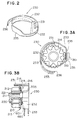
- Pinion rotation restriction member 230 is a plate spring member that is wound approximately one and a half times as shown in Fig. 2, Figs. 3A and 3B. Approximately half of the windings are rotation restriction portion 232 having a high spring constant with a long axial plate length, and the remaining approximately half of the windings is return spring portion 233 that acts as the low spring constant energizing means with the short axial plate length.
- Restriction claw 231 that forms the restriction portion extends in the axial direction to fit with multiple notches 214 formed on flange 213 of pinion gear 210 and is formed on one end of rotation restriction portion 232. Restriction claw 231 fits with notches 214 on pinion gear 210. Furthermore, to improve the rigidity of restriction claw 231, restriction claw 231 is formed to extend in the axial direction, and has a cross-sectional L-shape that is bent toward the inner radial direction. The claw is bar-shaped.
- Rotation restriction portion 232 has linear portion 235 that extends vertically.
- Linear portion 235 is supported to freely slide vertically between the two support arms 361 that are set to project on the front side of the center bracket. In other words, as linear portion 235 moves vertically, rotation restriction portion 232 also moves vertically.
- front end sphere 601 of string-shaped member 680 (for example, a wire) that conveys the movement of magnet switch 600, explained later, is fit.
- the curvature of the winding is large on an end portion side of return spring 233, and one end 236 of return spring portion 233 contacts the upper surface of restriction shelf 362 set to project to the lower front of center bracket 360.
- String-shaped member 680 is a conveyance means to convey magnet switch 600 operation to restriction claw 231.
- Rotation restriction portion 232 is pulled downward according to magnet switch 600 operation so that restriction claw 231 fits with one of notches 214 on flange 213 of pinion gear 210.
- one end 236 of return spring portion 233 contacts restriction shelf 362 to restrict the position, and return spring portion 233 slacks, i.e. loses some of its tension.
- Restriction claw 231 is fit with notch 214 of pinion gear 210, so that when rotation of pinion gear 210 is attempted with armature shaft 510 of the motor and epicycle speed reduction mechanism 300, pinion gear 310 advances along helical spline 221 of output shaft 220.
- pinion gear 210 contacts ring gear 100, and the advance of pinion gear 210 is thus prevented, pinion rotation restriction member 230 loses tension due to the further rotational force of output shaft 220.
- Pinion gear 210 will rotate slightly and engage with ring gear 100.
- restriction claw 231 is disengaged from notch 214, and restriction claw 231 drops behind the rear of flange 213 of pinion gear 210.
- the front end of restriction claw 231 contacts the rear surface of washer 215 and retraction of pinion gear 210 is prevented by rotation of engine ring gear 100.
- Pinion fitting ring 250 is fixed on the cross-sectional rectangular ring groove formed on the periphery of output shaft 220.
- Pinion fitting ring 250 is formed by round-machining cross-sectional rectangular steel material.
- Approximate S-shaped notches 251 are formed on both ends of pinion fitting ring 250 as shown in Figs. 4 and 6.
- One convex notch fits with the other concave notch, and one convex notch fits with the other concave notch.
- pinion fitting ring 250 is mounted from the front end of output shaft 220 and pinion fitting ring 250 is fit within the ring-shaped groove. Pinion fitting ring 250 is pressed and tightened toward the inner diameter side, and concave notches 251 on both ends thereof are mutually fit. This completes the assembly.
- Inner diameter D0 of pinion fitting ring 250 as shown in Fig. 4 is set to be larger than outer diameter D1 (Fig. 6) of output shaft 220, and width W of the ring-shaped groove on output shaft 220 is set larger than the width of convex portion width W1 (Fig. 5) added to facing convex portion width W1 of concave notches 251.
- Epicycle gear reduction mechanism or planetary gear speed reduction mechanism 300 shown in Fig. 1 is a deceleration means that decelerates rotation of motor 500, explained later, and increases the output torque of motor 500.
- Epicycle gear reduction mechanism 300 is composed of sun gear 310 formed on the front outer circumference of motor 500 armature shaft 510 (explained later), multiple planetary gears 320 engaged with sun gear 310 and that rotate around sun gear 310, planet carrier 330 that rotatably supports planetary gears 320 around sun gear 310 and that is integral with output shaft 220, and tubular resin internal gear 340 engaged with planetary gears 320 on the inner circumference thereof.
- Overrunning clutch 350 rotatably supports internal gear 340 in one direction (only in the direction rotatable with engine rotation).
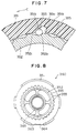
- Fig. 7 is a partial enlarged illustration of the overrunning clutch 350.
- Overrunning clutch 350 is made of clutch outer member 351 acting as the first cylindrical portion integrated with the front side of internal gear 340, ring-shaped clutch inner member 352 acting as the second cylindrical portion arranged to oppose the inner circumference of clutch outer member 351 and which is formed on the rear surface of center bracket 360 that acts as the fixing side that covers the front side of the epicycle gear mechanism 300, and roller 353 stored in roller storage portion 351a formed at an inclination to the inner circumference surface of clutch outer member 351.
- Roller storage portion 351a is inclined circumferentially, and has roller fitting surface 351b that fits with roller 353 during drawing of the starter having the reduction mechanism.
- Roller groove portions 355 are formed circumferentially on outer circumference of clutch inner member 352.
- Roller groove portions 355 comprise roller fitting surface 352b that fits with roller 353 when the starter having a reduction mechanism starts, and roller guide surface 352c that leads to roller storage portion 352b.
- roller storage guide portion 351d On the opposite surface of roller fitting surface 351b of roller storage portion 351a, is roller storage guide portion 351d that functions to lift roller 353 up to roller storage portion 351a when the starter with the reduction mechanism overruns.
- the above structure is provided circumferentially at a plurality of locations.
- clutch outer member 351, roller fitting surface 351b, and clutch inner member 352 is such that roller fitting surface 352b is configured so that roller 353 is sandwiched from before and after the torque conveyance direction by each surface when the starter having the reduction mechanism is driven.
- Roller storage portion 351a of clutch outer member 351 is set so that the maximum inner diameter of roller 353 is slightly larger than the maximum outer diameter of clutch inner member 352 when the rollers are stored during overrunning of the starter having the reduction mechanism.
- Center bracket 360 shown in Figs. 8 through 10 is arranged inside the rear side of housing 400. Housing 400 and center bracket 360 are coupled with ring spring 390 having one end fit to housing 400 and the other end fit to center bracket 360.
- the rotational reaction received by clutch inner member 352 that configures overrunning clutch 350 is absorbed by ring spring 390 so that the reaction is not directly conveyed to housing 400.
- Two support arms 361 that hold pinion rotation restriction member 230 and restriction shelf 362 mounted on the lower end of pinion rotation restriction member 230 are set on the front of center bracket 360. Furthermore, multiple notched portions 363 that engage with the convex notched portions (not illustrated) on the inner side of housing 400 are formed on center bracket 360. Upper notched portions 353 are also used as air passages to lead air in housing 400 into yoke 501. This air flow operation is explained in detail in the cooling air section. Concave portions 364 are formed on the lower end of center bracket 360 to pass string-shaped members 680 (explained later) in the axial direction.
- Planet carrier 330 includes flange-shaped projection portion 331 that extends in the radial direction to support planetary gear 320. Pins 332 that extend toward the rear are fixed onto flange-shaped projection portion 331, and pins 332 rotatably support planetary gear 320 via metal bearing.
- Planet carrier 330 is rotatably supported by housing bearing 440 of which the front end is fixed on the inner front of housing 400 and center bracket bearing 380 fixed inside tubular portion 365 on the inner circumference of center bracket 360.
- Planet carrier 330 includes ring groove 334 on the front end position of inner tubular portion 365, and snap ring 335 is fit into ring groove 334.
- Rotatable washer 335 mounted to planet carrier 300 is inserted between snap ring 335 and front end of inner tubular portion 365.
- the backward movement of planet carrier 330 is restricted by the direct contact of snap ring 335 to the forward end of inner tubular portion 365 via washer 336.
- the rear end of center bracket bearing 370 that supports the rear side of planet carrier 330 has flange portion 371 sandwiched between the rear end of inner tubular portion 365 and flange-shaped projection portion 331.
- the forward movement of planet carrier 330 is restricted by the direct contact of flange-shaped projection portion 331 to the rear end of inner tubular portion 365 via flange portion 371.
- Concave notch 337 that extends radially is created on the rear side of planet carrier 330.
- the forward end of the rotatable armature shaft 510 is supported via planet carrier bearing 380 arranged in concave notch 337.
- housing 400 supports output shaft 220 with housing bearing 440 fixed on the inner front end of housing 400. Further, housing 400 has water barrier wall 460 that acts as a projection portion to keep the clearance between housing 400 and the outer diameter of pinion gear 210 at the lower portion of opening 410 at a minimum to reduce the amount of rain water, etc., that enters through opening 410 (Figs. 1 or 11). On the lower front end of housing 400, two sliding grooves 450 that extend axially are created, and shutter 420, explained later, is set in slide grooves 450.
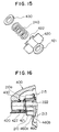
- Shutter 420 is made of a resin material such as nylon, and is mounted on the periphery of output shaft 220 as shown in Figs. 13 through 16.
- Shutter 420 is formed of ring body 421 sandwiched between return spring 240 and pinion gear 210, and water barrier portion 422 that opens and closes opening portion 410 of housing 400.
- Water barrier portion 422 is bent so that it fits slide grooves 450 formed on the lower front end of housing 400 and that extend axially from both sides. This configuration makes movement of water barrier portion 422 possible only in the axial direction of housing 400 together with ring body 421.
- a washer is installed between shutter 420 and pinion gear 210.
- seal member 430 has ring groove 430a on the side thereof, and one end of return spring 240 is disposed in ring groove 430a. Seal member 430 seals the periphery of output shaft 220, and prevents rain water and dust that have entered through opening portion 410 of housing 400 from entering housing bearing 440 on the front end of housing 400.
- housing end seal member for example, paper with adhesive on one end
- housing end seal member 470 is adhered to the end portion opening side (left-most side) of housing 400 to plug the opening surface.
- Metal foil or resin sheets may be used for housing end seal member 470.
- the opening side can be plugged just by adhering the housing end seal member 470 to the end portion opening of the housing 400, so assemblying is possible with simple work, and entering of foreign matters into the housing 400 via the housing bearing 440 can be inexpensively and securedly prevented.
- Metal foil or resin sheet can be used for the housing end seal member 470.
- Motor, starter motor, 500 is enclosed by yoke 501, motor wall 800 and brush holding member 900, explained later.
- Motor wall 800 sandwiches epicycle gear mechanism 300 between center bracket 360, and prevents lubrication oil in the epicycle gear mechanism from entering starter motor 500.
- starter motor 500 is composed of armature shaft 510, armature 540 fixed to armature shaft 510 and composed of armature core 520 and armature coil 530 that integrally rotate, and field magnetic pole 550 that rotates armature 540.
- Field magnetic pole 550 is fixed to the inner circumference of yoke 501.
- Armature shaft 510 is rotatably supported by planet carrier bearing 380 on the inner rear of planet carrier 330 and brush holding member bearing 564 fixed on the inner circumference of brush holding member 900.
- the front end of armature shaft 510 is inserted through the inner side of epicycle gear reduction mechanism 300, and as mentioned above, sun gear 310 of epicycle gear reduction mechanism 300 is formed on the outer circumference of the forward end of armature shaft 510.
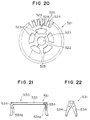
- Armature core 520 is formed by stacking multiple core plates as shown in Fig. 20, and force fitting the armature shaft 510 in hole 522 formed in the center.
- Core plate 521 is punched out of thin sheet plate on a press, and treated with surface insulation.
- Multiple (for example twenty-five) slots are formed on the outer circumference of core plate 521 to store armature coil 530.
- Fixing claws 525 are formed between each slot 524 on the outer circumference end portion of core plate 521 to fix the armature coil stored in slots 524. Fixing claws 525 will be described in the fixing procedure of armature coil 530.
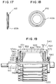
- FIG. 19 multiple (for example twenty-five) upper armature coils 531 and the same number of lower armature coils 532 are used for armature coil 530.
- Each of upper armature coils 531 and lower armature coils 532 are radially piled to form two layer winding coils.
- Each upper armature coils 531 and each lower armature coils 532 is combined, and the ends of each upper armature coils 531 and each lower armature coils 532 are operatively and electrically connected to form a ring-shaped coil.
- Upper armature coil 531 composed of a material such as copper, which has an outstanding conductivity, has upper coil piece 533 that is held in the outer circumference of slot 524, and that extends parallel to field magnetic pole 550, and has two upper coil ends 534 that are bent inward from both ends of upper coil piece 533 and that extend perpendicular in the axial direction of armature shaft 510.
- Upper coil piece 533 and upper coil ends 534 can be integrally shaped using cold forging, bent and formed in a U-shape with a press. Alternatively, upper coil piece 533 and upper coil ends 534 can be separately formed and then connected via welding.
- Upper coil piece 533 is a linear bar with a rectangular cross-section as shown in Figs. 21 through 24.
- the periphery of upper coil piece 533 is covered with an upper insulating film 125 (e.g., thin resin nylon film or paper).
- Upper coil piece 533 is firmly stored in slot 524 with lower coil piece 536, explained later, as shown in Fig. 24.
- one of upper coil ends 534 is inclined to the forward side in the rotating direction, and the other upper coil end 534 is inclined to the backward side in the rotating direction.
- the pair of upper coil ends 534 are inclined to the radial direction at the same angle to upper coil piece 533 and formed in the same shape. Therefore, even if upper coil ends 534 are horizontally turned 180° around the center of upper armature coil 531, upper armature coil 531 retains the same shape as before reversal. In other words, as there is no difference between upper coil ends 534, the assembly of upper armature coil 531 onto armature core 520 becomes easier.
- upper coil end 534 positioned at the side of magnet switch 600 directly contacts brush 910, explained later, and electrically energizes armature coil 530. Because of this, at least the surfaces of upper coil ends 534 that contact brush 910 are smooth.
- the starter having a reduction mechanism does not require a separate commutator for electrically energizing armature coil 530. In other words, as a separate commutator is not required, the number of parts required can be reduced. Furthermore, as the number of steps in the manufacturing process for the starter having the reduction mechanism is reduced, the manufacturing costs can be suppressed. As a separate commutator does not need to be arranged in the starter having the reduction mechanism so the structure of the starter with reduction mechanism can be reduced in size in the axial direction.
- the shape of upper coil end 534 gradually expands in the radial direction, and the circumferential clearance 535 of each upper coil end 534 is maintained to be almost uniform from the inner circumference to the outer circumference. This enlarges the contact area between upper coil end 534 and brush 910, which in turn allows the heat from brush 910 to be easily transmitted to the armature coil, and the temperature of brush 910 to be drastically suppressed.
- Fig. 25 is provided only to explain the shape of upper coil end 534 clearly, and the number of upper coil ends 534 does not match the number of slots 524 shown in Fig. 20.
- Space grooves 535 are formed by the clearances between respective upper coil ends 534 that contact brush 910.
- the shape of space grooves 535 are an approximate spiral that develops backwards in the rotating direction toward the outer diameter as shown in Fig. 25.
- Space grooves 535 of the clearances between each upper coil end 534 act as a cooling fan to cool the sliding surfaces of brush 910 and upper coil end 534.
- armature coil 530 rotates, the centrifugal wind from space grooves 535 flows from the inner diameter to the outer diameter.
- the centrifugal wind generated by the rotation of each space groove 535 of upper coil end 534 that contacts brush 910 cools the heat generated by the sliding of brush 910 and upper coil end 534, and also acts to discharge brush powder to the outside.
- Both upper coil ends 534 have small diameter projections 534a (Fig. 21) that project axially towards the surface where each end faces the other on the outer circumference. Projections 534a are disposed between upper coil end 534 and lower coil end 537, explained later, and are fit with holes 561 (equivalent to the positioning portion) formed on insulation spacer 560 (equivalent to the insulation body) that insulates upper coil end 534 and lower coil end 537 (Fig. 26)
- lower armature coil 532 includes lower coil piece 536 composed of a material such as copper having an outstanding conductivity that is held in the outer circumference of slot 524, that extends in parallel to field magnetic pole 550, and that has two lower coil ends 537 that are bent inward from both ends of the lower coil piece 536 and that extend perpendicularly in the axial direction of the shaft 510.
- Lower coil piece 536 and both lower coil ends 537 can be integrally formed via cold casting, bent and formed in a U-shape with a press, or can be separately formed as lower coil piece 536 and two lower coil ends 537 that are connected by welding, etc., as with upper armature coil 531.
- each upper coil end 534 and each lower coil end 537 is ensured with insulation spacer 560.
- the insulation between each lower coil end 537 and armature core 520 is ensured with a resin (e.g., nylon or phenol resin) insulation ring 590 as shown in Fig. 19.
- a resin e.g., nylon or phenol resin
- lower coil piece 536 is a linear bar with rectangular cross-section. This piece is firmly held in slot 524 with upper coil piece 533 as shown in Fig. 19 or Fig. 24.
- Lower coil piece 536 is covered with lower insulating film 105 (e.g., nylon or paper) and is stored in slot 524 with upper coil piece 533 covered with upper insulating film 125.
- lower insulating film 105 e.g., nylon or paper
- lower coil end 537 positioned on the front of the starter having the reduction mechanism is set to incline in a direction reverse of the inclined direction of upper coil end 534.
- Lower coil end 537 on the rear side is also set in a direction reverse to the inclined direction of upper coil end 534.
- Both lower coil ends 537 are inclined to the radial direction at the same angle to lower coil piece 536 and formed in the same shape.
- upper armature coil 531 With this structure even if lower coil ends 537 are turned 180° around the center of lower armature coil 532, lower armature coil 532 retains the same shape as if lower coil ends 537 are not turned.
- the assembly of lower armature coil 532 onto armature core 520 may be performed quicker and easier.
- Each cross-sectional area of lower coil piece 536 and two lower coil ends 537 that form lower armature coil 532 are set smaller compared to the cross-sectional area of the upper coil piece 533 and two upper coil ends 534 that form upper armature coil 531. This is due to the fact that the entire length of upper armature coil 531 is longer than the entire length of lower armature coil 532, and if upper armature coil 531 and lower armature coil 532 have the same area, the electrical resistance of lower armature coil 532 will be lower than upper armature coil 531, and a difference will occur in the power supplied to upper armature coil 531 and lower armature coil 532.
- lower armature coil 532 cross-sectional area was set to be less than the cross-sectional area of upper armature coil 531 to eliminate the difference in the electrical resistance between upper armature coil 531 and lower armature coil 532. This allows the power energized to each upper armature coil 531 and the power energized to each lower armature coil 532 to be the same, and the trouble of power being supplied mainly to the upper armature coil 531 is eliminated.
- the cross-sectional area of lower coil piece 536 is shown to be larger than the cross-sectional area of upper coil piece 533 in Fig. 24, however, the main purpose of this illustration is to show the storage state of upper coil piece 533 and lower coil piece 536. Thus, the actual cross-sectional area of lower coil piece 536 is smaller than the cross-sectional area of upper coil piece 533.
- Lower axial projection portion 539 that extends axially is created on the inner circumference ends of both lower coil ends 537.
- the outer circumference of lower axial projecting portion 539 fits with inner radial concave portion 562 formed on the inner circumference of insulation spacer 560, and is layered on the inner circumference of upper axial projection portion 538 of the inner end of upper coil end 534.
- the layered portion is electrically and mechanically connected with connection technology such as welding.
- the inner circumference of lower axial projecting portion 539 is insulated and disposed away from armature shaft 510.
- Upper axial projection portion 538 that extends axially is created on the inner circumference ends of both upper coil ends 534.
- Lower axial projection portion 539 on the inner end of lower armature coil 532 explained above is layered with the inner circumference of upper axial projection portion 538. These are electrically and mechanically connected with connection technology such as welding.
- the outer circumference of upper axial projection portion 538 contacts the inner surface of outer circumference ring portion 571 of fixing member 570 press-fixed onto armature shaft 510 with insulation cap 580 (Figs. 27 and 28).
- Insulation spacer 560 is a thin plate ring made of resin (e.g., epoxy resin, phenol resin, nylon). Multiple holes 561 (equivalent to positioning portion) into which projections 534a of upper coil ends 534 fit are formed on the outer circumference as shown in Fig. 26. Inner radially concave portions 562 into which lower radially projection portions 539 on the inner side of lower coil ends 537 fit are formed on the inner circumference of insulation spacer 560. As explained later, holes 561 and inner radially concave portions 562 are used for positioning and fixing armature coil 530.
- resin e.g., epoxy resin, phenol resin, nylon.
- Collar or fixing member 570 is an iron ring-shaped body. As shown in Fig. 27, collar 520 comprises inner ring-shaped portion 572 press-fit onto armature shaft 510, restricting ring 573 extending in the radial direction to prevent upper coil ends 534 and lower coil ends 537 from widening in the axial direction, and outer ring-shaped portion 571 housing upper inner projecting portions 538 of upper coil ends 534 to prevent the internal diameter of armature coil 530 from enlarging due to the centrifugal force. Collar 570 here has disc-shaped insulation cap 580 made of resin (e.g., nylon), illustrated in Fig. 28, at the ends of upper coil end 534 and lower coil end 537 for electrical insulation.
- resin e.g., nylon
- Collar 570 disposed in front of the starter contacts the rear of motor wall 800, which is positioned in front of collar 570 to function as a thrust pad for restricting the forward movement of armature 540.
- Collar 570 disposed at the back of the starter having the reduction mechanism contacts the front of brush holding member 900 to function as a thrust pad from restricting the backward movement of armature 540.
- Each collar 570 fixing the inner end portions of armature coil 530 function as thrust pads for armature coil 530 as described above, so there is no need to provide any special thrust pad for armature 540. This allows the number of parts required for the starter having the reduction mechanism in addition to the number of assembling man-hours for each such starter to be reduced.
- Slot 524 and fixing claw 525, insulation spacer 560, hole 561, inner radially concave portion 562, and collar 570 press-fit into armature shaft 410 are provided as means to position and fix the upper armature coil 531 and lower armature coil 532 of armature coil 531 to the armature core 530.
- Slot 524 of armature core 520 houses the upper coil piece 533 and lower coil piece 536, and by bending the fixing claws 525 toward the inside diameter as shown by the arrows in Fig. 24, upper coil piece 533 and lower coil piece 536 are firmly fixed into each slot 524 so that movement of upper coil piece 533 and lower coil piece 536 toward the outer diameter due to centrifugal force can be prevented.
- As the outer circumference surface of the upper coil piece 533 is insulated from lower insulating film 105 and upper insulating film 120 layers, sufficient insulation can be maintained even when the fixing claws are forcibly bent inward.
- Collar 570 hold upper inner projection portion 538 and lower inner projection portion 539 joined to prevent the movement of the inside diameter portion of armature coil 530 toward the outside diameter due to the centrifugal force applied.
- Collars 570 also restrict the movement of the axial end portion of upper inner projecting portion 538 and lower inner projecting portion 539 joined to prevent elongation of the axial length of armature coil 530.
- an extra space within the starter must be secured in the starter with reduction mechanism to accommodate the elongation.
- the collars 570 prevent the elongation of the axial length of upper coil ends 534 and lower coil ends 537 so the starter having the reduction mechanism does not require any extra space. This allows, the axial length of the starter having the reduction mechanism to be shortened.
- armature core 520 including stacked core plates 521 is press-fit around armature shaft 510.
- the insulation rings 590 are disposed at both sides of armature core 520.
- lower coil pieces 536 of lower armature coil 532 are stored with lower insulating film 105 into each slot 524.
- insulation spacers 560 are mounted on both sides of lower coil ends 537 of lower armature coil 532, and lower axial projection portions 539 are arranged within each inner radially concave portion 562. This completes the positioning of lower armature coil 532.
- the upper coil pieces 533 of the upper armature coil 532 are stored with the upper insulating film 125.
- the projections 534a on each upper coil end 534 are fit into the holes 561 on the insulation spacer 560. This completes the positioning of the upper armature coil 531.
- upper coil ends 534 on both ends of upper armature coil 531 and lower coil ends 537 on both ends of lower armature coil 532 that form armature coil 530 are each set to be perpendicular to the axial direction of armature shaft 510. This allows the axial length of armature 540 to be shortened, and as a result the starter with reduction mechanism is smaller compared to conventional models.
- the axial length of the starter having a reduction mechanism does not differ much from the conventional model.
- the space for the magnet switch 600 conventionally mounted on top of starter motor 500 is not required, the volume of the starter with a reduction mechanism is dramatically smaller than the conventional model.
- the resonance frequency of armature 540 can be set higher, and jumping, etc., of the brush due to vibration of the armature 540 can be prevented.
- armature coil 530 As the axial length of upper coil end 534 and lower coil end 537 of armature coil 530 is short, and upper coil piece 533, lower coil piece 536, upper coil end 534, and lower coil end 537 are firmly fixed to armature core 520 and armature shaft 510, trouble such as armature coil 530 deviating from armature core 520 due to centrifugal force will not occur even if armature 540 is rotated at a high speed.
- yoke 501 having a hole 503 is a cylindrical body formed by rounding a steel plate. Multiple concave grooves 502 that extend axially and face the inner circumference are formed on the circumference. Concave grooves 502 are used to arrange the through bolts and also to position the field magnetic pole 440 within the inner circumference of yoke 501.
- field magnetic pole 550 is configured of multiple (e.g., six) main magnetic poles 551 as shown in Fig. 29, and inter-pole magnetic poles arranged between the main magnetic poles 551.
- Field coils that generate a magnetic force electrically can be used instead of the permanent magnets.
- Main magnetic poles 551 are positioned by both ends of the inner side of concave grooves 502 on yoke 501 described above. These are fixed to the inside of yoke 501 by fixing sleeve 553 arranged on the inner circumference of field magnetic pole 550, with the inter-pole magnetic poles arranged between the main magnetic poles.
- Fixing sleeve 553 is a nonmagnetic (e.g., aluminum) sheet that has been round-machined. Both ends 554 in the axial direction are bent to face the outer diameter, and to prevent field magnetic poles 550 from deviating in the axial direction of yoke 501. As shown in Fig. 30, fixing sleeve 553 has two end pieces 555 and 556 (first end portion and second end portion) that abut inside field magnetic poles 550. One of end pieces 555 is set to be linearly inclined to the axial direction, and end piece 556 is set to gradually curve and incline to the axial direction.
- end pieces 555 is set to be linearly inclined to the axial direction
- end piece 556 is set to gradually curve and incline to the axial direction.
- fixing sleeve 554 can be enlarged to the outer diameter side by axially deviating the butt position of one end piece 555 and other end piece 556 to absorb this error.
- the diameter dimensions of fixing sleeve 554 are fixed, so field magnetic poles 550 are firmly held between fixing sleeve 553 and yoke 501.
- the magnet switch 600 is held by the brush holding member 900, explained later, and is arranged in end frame 700, explained later. Magnet switch 600 is fixed to be approximately perpendicular to armature shaft 510.
- magnet switch 600 drives plunger 610 upward, and contacts the two contacts (lower movable contact 611 and upper movable contact 612) that move integrally with plunger 610 to sequentially contact with head 621 of terminal bolt 620 and contact portion 631 of fixed contact 630.
- the battery cable may be connected to terminal bolt 620.
- Magnet switch 600 is configured inside magnet switch cover 640, which is a magnetic (e.g., iron) tube with base.
- Magnet switch cover 640 is formed by pressing a mild steel plate into a cup shape for example, and has hole 641 at the center of the base for passing plunger 610 freely in the vertical direction.
- the upper opening of magnet switch cover 640 is plugged by magnetic (e.g., iron) stationary core 642.
- Stationary core 642 is configured of upper large diameter portion 643, lower middle diameter portion 644 and lower small diameter portion 645.
- the outer circumference of larger diameter portion 643 tightens the upper end of magnet switch cover 640 to the inner side so that stationary core 642 is fixed in the upper opening of magnetic switch cover 640.
- the upper end of attraction coil 650 is mounted to the periphery of middle diameter portion 644.
- the upper end of compressed coil spring 660 that energizes plunger 610 downward is mounted onto the outer circumference of small diameter portion 645 of stationary core 642.
- Attraction coil 650 is an attraction means for pulling plunger 610 closer, and is magnetized when power is passed through it.
- the upper end of attraction coil 650 is mounted on middle diameter portion 644 of stationary core 642, and has sleeve 651 that slides and freely covers plunger 610 in the vertical direction.
- Sleeve 651 is made by round-machining a nonmagnetic (e.g., copper, brass, stainless steel) thin plate, and insulation washers 652 made of resin, etc., are set on the upper and lower ends of sleeve 651.
- An insulating film (not illustrated) made of a thin resin (e.g., cellophane, nylon film) or paper is wound around the periphery of sleeve 651 between insulation washers 652.
- a fine enamel wire is wound a designated number of times around the periphery of the insulating film to configure attraction coil 650.
- Plunger 610 is made of a magnetic metal (e.g., iron), and has a columnar-shape that has upper small diameter portion 613 and lower large diameter portion 614.
- the lower end of compression coil spring 660 is mounted to small diameter portion 613, and large diameter portion 614, having a relatively long axial direction, is held so that it can move vertically inside sleeve 651.
- Plunger shaft 615 that extends upward from plunger 610 is fixed on the upper side of plunger 610. Plunger shaft 615 protrudes upward from the through hole on the center of stationary core 642. Upper movable contact 612, which slides freely through the vertical direction along plunger shaft 615, is disposed on the upper side of plunger shaft 615 above stationary core 642.
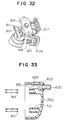
- Upper movable contact (first movable contact) 612 is restricted from moving over the upper end of plunger shaft 615 by fixing ring 616 installed on the upper end of plunger shaft 615 as shown in Fig. 31. As a result, upper movable contact 612 slides freely in the vertical direction along plunger shaft 615 between fixing ring 616 and stationary core 642. Upper movable contact 612 is constantly energized upwards by contact pressure spring 670 formed by the plate spring installed on plunger shaft 615.
- Upper movable contact 612 is composed of a metal such as copper having an outstanding conductivity. When upper movable contact 612 moves upward, both contact portions 631 on fixed contact 630 are contacted by the ends of contact 612. Each lead wire 910a for brushes 910 is electrically and mechanically connected with caulking or welding to upper movable contact 612. The ends of resistors 617 that act as multiple restriction means (two in this embodiment) are inserted and electrically and mechanically fixed to the grooves on upper movable contact 612. Each lead wire 910a for brushes 910 is electrically and mechanically connected with caulking or welding to upper movable contact 612, however, upper movable contact 612 and each lead wire 910a of brush 910 can be integrally formed.
- Resistor 617 is used as an eleastic resistor member to slow rotation of starter motor 500 when the starter initially starts. Metal wires with a large resistance value are wound to configure the resistor 617 which is elastic. Resistor 617 comprises a first approximately linear portion 617a that directly contacts the first movable contact 612, a spiral portion 617c connected to one end of the first linear portion 617a, and a second approximately linear portion 617b that extend toward the position that opposes fixed contact 630 connected to spiral portion 617c.
- lower movable contact 611 to second direct contact portion 621 is made shorter than that from upper movable contact 612 to first direct contact portion 631 is.
- Lower movable contact 611 disposed below head portion 621 of terminal bolt 620 is fixed with caulking, etc., to the other end of resistor 617.
- Lower movable contact (second movable contact) 611 is composed of a metal such as copper having an outstanding conductivity. This contacts the upper surface of stationary core 642 when magnet switch 600 stops and plunger 610 is at the lower position. When resistor 617 moves upward with the movement of plunger shaft 615, lower movable contact 611 will contact head portion 621 of terminal bolt 620 before upper movable contact 612 contacts contact portion 631 of fixed contact 630.
- Concave portion 682 is formed on the bottom side of plunger 610 to store spherical body 681 set on the rear end of string-shaped member 680 (e.g., wire).
- Male screw 683 is formed on the inner wall of concave portion 682, and fixing screw 684 that fixes spherical body 681 is screwed into male screw 683.
- the length of the string-shaped member 680 is adjusted by adjusting the amount that fixing screw 684 is screwed into male screw 683.
- the length of string-shaped member 680 is adjusted so that when plunger shaft 615 moves upward and lower movable contact 611 contacts terminal bolt 620, restricting claw 231 of pinion rotation restricting member 230 fits into notch 214 on the outer circumference of pinion gear 210.
- Male screw 683 and fixing screw 683 act as adjustment mechanism.
- restriction claw 231 of pinion rotation restriction member 230 only needs to be fit with notch 214 formed on pinion gear 210, restriction claw 231 can be accurately moved by string-shaped member 680.
- string-shaped member 680 By using a wire for string-shaped member 680, the durability can be improved.
- the adjustment mechanism configured of male screw 683 and fixing screw 684 between plunger 610 and string-shaped member 680, the length of string-shaped member 680 can be easily determined by screw the fixing screw 684 into the male screw 683.
- each lead wire 910a of brush 910 is directly connected to upper movable contact 612, the heat generated at brush 910 is efficiently dissipated via upper movable contact 612 and terminal bolt 620 through the battery cable connected to terminal bolt 620 and positioned outside the starter. This thereby extends the life of brush 910.
- the axial length of the starter can be reduced compared to the structure in which the plunger shaft of the magnet switch is laid axially.
- the stroke of plunger shaft 615 required for pulling string-shaped member 680 can be set to a smaller value, so magnet switch 600 can be further reduced in size.
- magnet switch 600 is laid to intersect perpendicularly to the axial direction of armature shaft 510, only the radial length of magnet switch 600 is added to the entire axial length of the starter, and the entire starter size does not need to be large.
- the end frame 700 is a magnet switch cover made of resin such as phenol resin. Magnet switch 600 is stored inside end frame 700.
- Spring holding poles 710 that hold compressed coil spring 914, which energize brushes 910 toward the front is installed on the rear side of end frame 700 to protrude forward according to the position of brushes 910.
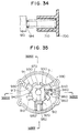
- Each compressed coil spring 914 is tapered as shown in Fig. 34, and the diameter of the side inserted into the spring holding column 710 is wider than the side protruding from column 710.
- Spring holding column 710 can be tapered and the diameter of the side in which compressed coil spring 914 is inserted can be increased instead.
- Compressed coil spring 914 is disposed outside magnet switch 600 so as to overlap the radial direction outer circumference to the axial direction of plunger 610 of magnet switch 600 as shown in Fig. 1.
- Terminal bolt 620 is an iron bolt inserted from inside end frame 700 to project from the rear of end frame 700, and has head portion 621 on the front that contacts the inner surface of end frame 700. Terminal bolt 620 is fixed to end frame 700 by installing caulking washer 622 on terminal bolt 620 projecting from the rear of end frame 700 as shown in Fig. 33.
- Copper fixed contact 630 is caulked and fixed onto the front end of terminal bolt 620.
- Fixed contact 630 has one or multiple (six in this embodiment) contact portions 631 positioned on the inner upper end of end frame 700.
- the upper surface of upper movable contact 612 that moves vertically with magnet switch 600 operation is set to contact the lower surface of contact portion 631.
- compressed coil spring 914 can be used to the radial length of magnet switch 600, an adequate spring stress and load can be set thereby drastically improving the life of the compressed coil spring 914. Furthermore, compressed coil spring 914 effectively uses the space on the outer circumference of magnet switch 600 so the length of compressed coil spring 914 is not added to the axial length of the starter, and the entire starter can be reduced in size.
- Brush holding member 900 separates the inner side of yoke 501 and inner side of end frame 700 and functions to rotatably support the end of armature shaft 510 via brush holder bearing 564.
- brush holding member 900 can act as the brush holder, can support magnet switch 600, and can hold pulley 690 that guides string-shaped member 680.
- Brush holding member 900 has a hole, not illustrated, through which string-shaped member 680 passes.
- Brush holding member 900 is a partition made of cast metal such as aluminum. As shown in Figs. 35 and 37, there are multiple brush holding holes 911 and 912 (two on top and two on bottom in this embodiment) that hold brushes 910 in the axial direction.
- Upper brush holding hole 911 is a hole that holds brush 910 that receives a positive voltage, and upper brush holding hole 911 holds brush 910 via a resin (e.g., nylon, phenol resin) insulation cylinder 913.
- Fig. 36 illustrates a cross-sectional view taken along the line XXXVI-XXXVI in Fig. 35 while Fig. 37 is a cross-sectional view along the line XXXVII-XXXVII in Fig. 35.
- Lower brush holding hole 912 is a hole that holds brush 910 connected to the ground, and lower brush holding hole 912 directly holds the brush 910 inside the hole.
- Brush 910 is formed by forming metallic powder such as graphite powder or copper powder and a crystallizing resin in a shape having approximately a rectangular cross-sectional shape, and is then baked.
- Lead wire 910a is connected to the side of the rear end of brush 910 by welding, etc.
- the effective length of brush 910 can be long.
- brush 910 is a surface-type brush 910 that energizes the brush in the axial direction such as in this embodiment, the length of brush 910 affects the entire length of the starter having the reduction mechanism. Therefore, using the brush 910 in this embodiment that can suppress the axial length of the brush and have a longer effective brush length is especially effective.
- the front end of brush 910 is energized by compressed coil spring 914 to the rear side of upper coil end 534 on the rear side of armature coil 530.
- Lead wire 910a of brush 910 is electrically and mechanically connected by welding or caulking, etc., to upper movable contact 612 that moves with magnet switch 600.
- Lead wire 910a of lower brush 910 is electrically and mechanically connected by caulking to concave notch 920 formed on the rear side of brush holding member 900.
- the center of lead wire 910a is caulked to concave notch 920 on the rear side of brush holding member 900.
- Two washers 930 to which the front end side of magnet switch 600 contact and two fixing columns 940 that enclose the periphery of magnet switch 600 are formed on the rear side of brush holding member 900.
- washers 930 contact magnet switch 600, which has a cylindrical outer diameter
- washers 930 are set to match the outer shape of magnet switch 600.
- Fixing columns 940 are caulked to the inner side of the rear end in the state with magnet switch 600 contacting washers 930 to hold magnet switch 600.
- Pulley holding portion 950 that holds pulley 690, which converts the movement direction of string-shaped member 680 from the vertical direction of magnet switch 600 to the axial direction, is formed on the lower rear side of brush holding member 900.
- Holding portion 960 holds the temperature switch (not illustrated) for overheat protection.
- Holding portion 960 is formed on the rear side of brush holding member 900.
- Holding portion 960 holds the temperature switch between upper brush holding hole 911 and lower brush holding hole 912 so that it is near magnet switch 600. When this temperature switch reaches a predetermined temperature, magnet switch 600 turns OFF, and the power to the starter motor having a reduction mechanism is cut off to protect the equipment.
- the front side of brush holding member 900 is set to be near the rear side of upper coil end 534 that contacts with brush 910. Therefore, the centrifugal wind generated by the rotation of space grooves 535 between each upper coil end 534 is forcibly guided in the outer radial direction. In other words, a centrifugal wind is generated between the rear side of upper coil end 534 and brush holding member 900.
- a cooling air passage is formed in the starter having the reduction mechanism as shown in Fig. 39 for guiding air to the inner side of the space between the rear side of upper coil end 534 and brush holding member 900, and to discharge the centrifugal wind to the external environment.
- This cooling air passage is configured of guiding inlet 970 opened into the inner circumference portion of brush holding member 900 and which guides the air in end frame 700 to the inner side between rear upper coil end 534 and brush holding member 900, the inner portion of end frame 700, brush holding member communicating holes 980 formed on the upper periphery of brush holding member 900 and that communicate with the clearances between main magnetic poles 551 in yoke 501, the clearance between main magnetic poles 551 that communicate with brush holding member communicating holes 980, communicating hole 810 formed in the upper periphery of the motor wall 800 and that communicates with the clearance between the main magnetic poles 551, notched portion 363 on the upper side of center bracket 360 that communicates with motor wall communicating hole 810, and the inside of the housing 400.
- the air drawn in from opening portion 410 of housing 400 passes via the inside of housing 400 to notched portion 363 on the upper side of the center bracket 360 through motor wall communicating hole 810 through the clearance between main magnetic poles 551 through brush holding member communicating hole 980 and then circulates inside end frame 700 to guide inlet 970, and then flows to the inner side of the space between the rear side of upper coil end 534 and brush holding member 900.
- the centrifugal force generated between the rear side of upper coil end 534 and brush holding member 900 cools the sliding surface and periphery of brush 910, and is then discharged with the brush powder generated on the sliding surface through discharge hole 503 formed in the bottom end of yoke 501 and then exits the starter having the reduction mechanism.
- upper coil end 534 that functions as a commutator also functions as a centrifugal fan to generate a centrifugal wind.
- the temperature of the sliding portion between upper coil end 534 and brush 910 can be maintained at a low level.
- the brush powder generated due to wearing of brush 910 is carried to the discharge hole 503 by the centrifugal wind and is then discharged through hole 503, trouble or problems that may be caused by accumulation of brush powder in the operational mechanisms of the present invention can be prevented.
- attraction coil 650 in magnet switch 600 is energized by battery 20.
- attraction coil 650 is energized, plunger 610 is attracted by the magnetic force generated by attraction coil 650 so that it is lifted upward.
- the voltage from battery 20 is applied to terminal bolt 620, and the voltage of terminal bolt 620 is conveyed to upper brush 910 via lower movable contact 611, resistor 617, upper movable contact 612 and lead wire 910a.
- the low voltage conveyed with the resistor 617 is conveyed to armature coil 530 via upper brush 910.
- armature coil 530 configured with upper armature coils 531 and lower armature coils 532 combined into a coil is energized with a low voltage.
- Armature coil 530 then generates a relatively weak magnetic force. This magnetic force acts on (attracts or repulses) the magnetic force of field magnetic poles 550, causing the armature 540 to rotate at a low speed.
- pinion gear 210 will also attempt to rotate, but as the rotation of pinion gear 210 is restricted by the pinion rotation restriction member 230, pinion gear 210 will advance along helical spline 221 of output shaft 220.
- rollers 353 of overrunning clutch 340 will separate from concave notches 355 on clutch inner member 352, and rotation of internal gear 340 will be possible.
- key switch 10 is removed from the start position by the operator, and the conductivity to attraction coil 650 in magnet switch 600 is stopped.
- the energizing the attraction coil 650 is stopped, plunger 610 will return downward due to the function of compressed coil spring 660.
- Upper movable contact 612 will be separated from contact portion 631 of fixed contact 630, and then lower movable contact 611 will also be separated from head portion 621 of terminal bolt 620 causing the conductivity to upper brush 910 to be stopped.
- Second movable contact 611 directly contacts the lower movable contact 621 and is coupled with elastic resistor member 617 that acts as a resistor.
- Upper movable contact 612 and elastic resistor member 617 are supported to move freely by plunger shaft 615.
- the plunger 610 is attracted by the attraction force of the attraction coil 650.
- Fixed contact 630 is set to oppose upper movable contact 612 and lower movable contact 611 and is electrically connected to the battery.
- Upper movable contact 612 directly contacts fixed contact 630 due to the movement of plunger 610 by the attraction force of attraction coil 650.
- a contact voltage is applied on the fixed contact 630 due to the elastic force of the elastic resistor member 617, causing the battery voltage to be conducted to motor 500 via upper movable contact 612, elastic resistor member 617 and lower movable contact 611.
- the upper movable contact 612 directly contacts the fixed contact 630 so that motor 500 is conducted.
- the elastic member 617 acts as a resistor and as the contact force spring having electric force, and has lower movable contact 611, so upper movable contact 612 and lower movable contact 611 can be directly contacted with fixed contact 630 in two steps.
- the upper movable contact 612 conducts motor 500 and lower movable contact 611 directly contacts the upper movable contact 612 and has elastic resistor member 617 that acts as resistor.
- the upper movable contact 612 and elastic resistor member 617 are supported to move freely by the plunger shaft 615.
- the plunger 615 is attracted by the magnetomotive force of the attraction coil 650.
- the fixed contact 630 is set to oppose the upper movable contact 612 and lower movable contact 611 and is electrically connected to the battery.
- Fixed contact 630 has first direct contact portion 631 to which upper movable contact 612 contacts and second direct contact portion 621 to which lower movable contact 611 contacts.
- the distance from the lower contact 611 to the second direct contact portion 621 is made shorter than the distance from upper movable contact 612 to the first direct contact portion 631 so lower movable contact 611 directly contacts the fixed contact 630 and thereafter the upper movable contact 612 directly contacts the fixed contact 630.
- upper movable contact 612 and lower movable contact 611 can be accurately contacted with fixed contact 630 in two steps.
- the elastic resistor member 617 formed of metal material comprises first approximately linear portion 617a that directly contacts the upper movable contact 612, spiral portion 617c connected to one end of first approximately linear portion 617a, and second approximately linear portion 617b connected to spiral portion 617c and that extends to a position that opposes fixed contact 630.
- the lower movable contact 611 is set in the second approximately linear portion 617b so the resistance value can be set freely in the spiral portion 617c.
- Permanent magnets are set as field magnet device in the motor 500.
- the elastic resistor member 617 directly contacts the grounding side member 640 (stationary core) of the battery, and the power input side member 910 (brush) of the motor 500 and the grounding side member 642 (stationary core) of the battery are electrically connected.
- the motor 500 rotates with a coasting rotation, and the power voltage generated by the electromotive force is short-circuited via elastic resistor member 617 composed of the resistor allowing the motor 500 to be stopped instantly.
- motor 500 is stopped instantly, so the life of brush 910 can be extended, and the size of the starter can be reduced without increasing the size of brush 910.
- lower movable contact 611 directly contacts the fixed contact 630, and the battery current is conducted via elastic resistor member 617 and upper movable contact 612 to rotate motor 500 at a low speed.
- the resistor member 617 can be connected to the fixed contact 630 by welding, etc., and the lower movable contact 611 connected and fixed to the resistor 617 placed between the fixed contact 630 and upper movable contact 612.
- the lower movable contact 611 directly contacts the upper movable contact 612 set on the plunger shaft 615 with the movement of plunger 610.
- the battery current is conducted via lower movable contact 611 and resistor member 617 to rotate motor 500 at a low rotation speed.
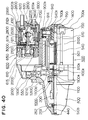
- the starter is largely comprised of housing 400 that covers overrunning clutch 1000 that has pinion 200 that engages the ring gear of the engine not illustrated, motor 500, end frame 700, and magnet switch 600.
- housing 400, motor 500 and end frame 700 will be explained.
- Fixed magnetic pole 550 (e.g., permanent magnets) is fixed on the inner circumference of yoke 501 of motor 500. Armature 540 supported by housing bearing 440 and end frame bearing 790 of end frame 700 is set on the inner circumference of these fixed magnetic pole 550. Armature shaft 510 is press-fit and fixed to the center of armature 540. Spline 510a is set on armature shaft 510, and overrunning clutch 1000 that slides axially over armature shaft 510 is engaged with spline 1100a that is set on clutch outer 1100 of overrunning clutch 1100. Groove 510b is formed on the outer circumference of one end of armature shaft 510. A C-clip 251 is mounted in groove 510b, and a ring-shaped nut pinion stop 252 is mounted on the outer circumference of C-clip 251. Thus, the movement of the overrunning clutch 1000 is restricted by nut pinion stop 252.
- a tubular commutator 540a is press-fit into the armature shaft 510 on a side opposing overrunning clutch 1000.
- the vertical movement of the armature 540 is restricted by directly contacting commutator 540a and washer 700a set in the inner circumference of end frame 700.
- the brush 910 is pressed against the radial outer circumference of commutator 540a by compressed coil spring 914.
- a shift lever 1200 that slides overrunning clutch 1000 is set in housing 400.
- One end of shift lever 1200 is engaged with the overrunning clutch 1000, and the other end is engaged with hook 1300 of magnet switch 600.
- a through bolt 1400 is inserted from the rear of bolt through hole 700a formed on the periphery of end frame 700. By screwing through bolt 1400 into the screw hole 400a formed on the rear of housing 400, the housing 400, yoke 501 of motor 500 and end frame 700 are fixed axially.
- magnet switch 600 resin case 2100 that holds attraction coil 650 in magnet switch frame 2000, and plunger 610 set to slide freely in the axial direction inside are arranged. On the other end of plunger 610, hook 1300 that fits with the shift lever 1200 is set.
- Welded and fixed plunger shaft 615 is set in plunger 610, and a pair of movable contacts, in other words, first movable contact 612 and second movable contact 611 are set on the end of plunger shaft 615.
- Resin bushings 612a and 611a are press-fixed into the inner sides of first movable contact 612 and second movable contact 611, respectively.
- the first movable contact 612 and second movable contact 611 are fixed to plunger shaft 615 via bushings 612a and 611a.
- a groove 615a is formed on the outer circumference of the tip of plunger shaft 615, and washer 2200 is formed and mounted on the inner surface of groove 615a.
- Insulation member 2300 that electrically insulates first movable contact 612 is set between washer 2200 and first movable contact 612.
- One end of second movable contact 611 contacts the stepped portion of bushing 611a, and the other end contacts insulation member 2400.
- Spring 2500 that ebiases second movable contact 611 in the direction of the hook 1300 is interposed between insulation member 2300 and insulation member 2400. Return spring 2500 is for biasing the plunger 610 in the return direction.
- Magnet switch cover 2600 formed of heat hardened resin is fixed by bending one end of magnet switch frame 2000.
- Terminal bolt 620 connected to the battery cable not illustrated and motor terminal bolt 3000 that connects motor lead wire 2700 of motor 500 are mounted on magnet switch cover 2500.
- the terminal bolt 620 welds and fixes copper plate 620b formed in an L-shape on one end of bolt portion 620a, and welds and fixes fixed contact 630 integrally formed with tongue piece 630b of U-shaped portion 630a of copper plate 620b.
- Motor terminal bolt 3300 is manufactured in the same manner as terminal bolt 620.
- the fixed contact 630 directly contacts with first movable contact 612 when electric power is conducted to attraction coil 650.
- conductive member 2800 By bending four tongue pieces 2800a of the copper plate inward to a position that opposes fixed contact 630 to form a box shape (concave portion) as shown in Fig. 42, conductive member 2800 is formed. Elastic member that acts as electrical resistor is set between concave portion of the conductive member 2800 and the U-shaped portion of the fixed contact 630. A groove 2900a is formed on the inner circumference of ring-shaped member 2900, and one of four tongue pieces 2800a of the conductive member 2800 is inserted in groove 2900a from the axial direction and welded and fixed. When the power is conducted to attraction coil 650, the conductive member 2800 contacts the second movable contact 611. The conductive member 2800 is set so that metal plate 3100 is contacted.
- a cylindrical resin portion 3000 is formed of resin, and L-shaped metal plate 3100 is fit and fixed into groove 3000a formed on one end of the resin member 3000 in the axial direction.
- the distance from the conductive member 2800 to the second movable contact 611 is set shorter than the distance from the fixed contact 630 to the first movable contact 612.
- second movable contact 611 and conductive material 2800 press the elastic resistor member 2900 and the first movable contact 612 also directly contacts fixed contact 630 as shown in Fig. 44B.
- the shift lever 1200 further presses the overrunning clutch 1000 starting at the support or pivot point 1210, and the engagement of pinion gear of the overrunning clutch 1000 and ring gear 100 is completed.
- the full voltage of the battery 20 is applied to motor 500 at this time, and armature 540 rotates at a high speed to start the engine.
- the overrunning clutch 1000 prevents the pinion 210 from retracting.
- the engine drive force prevents armature 540 from overrunning by idly running rollers 1000b inside clutch outer 1000a of overrunning clutch 1000.
- plunger 610 has plunger shaft 615 on which a pair of movable contacts, in other words, first movable contact 612 and second movable contact 611 are arranged, and first movable contact 612 and second movable contact 611 move with the magnetic force of attraction coil 650 toward fixed contact 630.
- the conductive member 2800 can move, and the elastic resistor member 2900 set between second movable contact 611 and fixed contact 630 functions as the resistor.
- One end of the member 2900 directly contacts conductive member 2800 and the other end directly contacts fixed member 630.
- the second movable contact 612 directly contacts conductive member 2800 with the movement of plunger 610 by the attraction force of attraction coil 650.
- a contact force is applied to conductive member 2800 by the elastic force of elastic resistor member 2900.
- the battery voltage is conducted to motor 500 through second movable contact 611, conductive member 2800, elastic resistor member 2900 and fixed contact 630.
- first movable contact 612 directly contacts fixed contact 630 to conduct the power to motor 500.
- elastic resistor member 2900 acts as the resistor and as the contact pressure spring having an elastic force, so first movable contact 612 and second movable contact 611 can directly contact fixed contact 630 in two steps.
- the plunger 610 has plunger shaft 615 on which a pair of movable contacts, in other words, the first movable contact 612 and second movable contact 611 are arranged, and first movable contact 612 and second movable contact 611 move with the magnetic force of attraction coil 650 toward fixed contact 630.
- the conductive member 2800 can move, and elastic resistor member 2900 set between second movable contact 611 and fixed contact 630 functions as the resistor.
- One end of reisitor member 2900 directly contacts conductive member 2800 and the other end directly contacts fixed member 630.
- the distance between conductive member 2800 and second movable contact 611 is shorter than the distance between fixed contact 630 and first movable contact 612, so second movable contact 611 directly contacts conductive member 2800 and then first movable contact 612 directly contacts fixed contact 630. Therefore, first movable contact 612 and second movable contact 611 accurately and directly contact conductive member 2800 and fixed contact 630.
- Permanent magnets are arranged as the field magnet device or fixed magnetic pole on motor 500, and after the battery voltage is conducted to motor 500, elastic member 2900 directly contacts grounding side member (metal plate 3100) of the battery, and the power input side member (brush 910) of motor 500 and the grounding side member of the battery are electrically connected. Therefore, when motor 500 coasts and rotates, the power voltage generated by the electromotive force is short-circuited through elastic resistor member 2900. This allows motor 500 to be instantly stopped. Furthermore, motor 500 is stopped instantly, so brush life can be extended, and the size of the starter can be reduced without increasing the size of brush 910.
- second movable contact 611 directly contacts conductive member 2800 and fixed contact 630 is conducted through resistor member 617 to rotate motor 500 at a low speed.
- second movable contact 511 directly contacts conductive member 2800 with fixed contact 630 via resistor member 617 and conductive member 2800 to rotate motor 500 at a low speed can be incorporated.
Landscapes
- Engineering & Computer Science (AREA)
- Chemical & Material Sciences (AREA)
- Combustion & Propulsion (AREA)
- Mechanical Engineering (AREA)
- General Engineering & Computer Science (AREA)
- Physics & Mathematics (AREA)
- Electromagnetism (AREA)
- Connection Of Motors, Electrical Generators, Mechanical Devices, And The Like (AREA)
- Relay Circuits (AREA)
Applications Claiming Priority (2)
| Application Number | Priority Date | Filing Date | Title |
|---|---|---|---|
| JP222326/94 | 1994-09-19 | ||
| JP22232694 | 1994-09-19 |
Publications (2)
| Publication Number | Publication Date |
|---|---|
| EP0702146A1 true EP0702146A1 (fr) | 1996-03-20 |
| EP0702146B1 EP0702146B1 (fr) | 1998-09-30 |
Family
ID=16780604
Family Applications (1)
| Application Number | Title | Priority Date | Filing Date |
|---|---|---|---|
| EP95101996A Expired - Lifetime EP0702146B1 (fr) | 1994-09-19 | 1995-02-14 | Interrupteur magnétique pour démarreur |
Country Status (7)
| Country | Link |
|---|---|
| US (1) | US5525947A (fr) |
| EP (1) | EP0702146B1 (fr) |
| KR (1) | KR0140786B1 (fr) |
| CN (1) | CN1063522C (fr) |
| AU (1) | AU679139B2 (fr) |
| DE (1) | DE69505079T2 (fr) |
| ES (1) | ES2121241T3 (fr) |
Families Citing this family (16)
| Publication number | Priority date | Publication date | Assignee | Title |
|---|---|---|---|---|
| JPH09195898A (ja) * | 1996-01-16 | 1997-07-29 | Denso Corp | スタータ |
| JP3796920B2 (ja) * | 1996-11-15 | 2006-07-12 | 株式会社デンソー | スタータ |
| JP3505979B2 (ja) * | 1997-10-20 | 2004-03-15 | 株式会社デンソー | スタータ |
| JP2003293913A (ja) * | 2002-04-03 | 2003-10-15 | Denso Corp | マグネットスイッチ |
| JP3885640B2 (ja) * | 2002-04-12 | 2007-02-21 | 株式会社デンソー | スタータ用マグネットスイッチ |
| US20040061387A1 (en) * | 2002-09-27 | 2004-04-01 | Harmonic Drive, Inc. | Magnetically actuated commutator |
| JP2004190561A (ja) * | 2002-12-11 | 2004-07-08 | Denso Corp | スタータ用電磁スイッチ及びスタータ |
| JP4123164B2 (ja) * | 2004-02-20 | 2008-07-23 | 株式会社デンソー | スタータ用電磁スイッチ |
| JP4661721B2 (ja) * | 2006-07-26 | 2011-03-30 | 株式会社デンソー | スタータ |
| JP2008163818A (ja) * | 2006-12-28 | 2008-07-17 | Hitachi Ltd | スタータ |
| US20110180770A1 (en) * | 2010-01-27 | 2011-07-28 | Warn Industries, Inc. | Light Weight Winch |
| CN104246208B (zh) * | 2012-05-17 | 2016-08-31 | 三菱电机株式会社 | 发动机启动装置 |
| JP5949651B2 (ja) * | 2013-04-23 | 2016-07-13 | 株式会社デンソー | スタータ |
| JP6379603B2 (ja) * | 2014-04-04 | 2018-08-29 | 株式会社デンソー | エンジン始動装置 |
| JP7298357B2 (ja) * | 2019-07-17 | 2023-06-27 | 株式会社デンソー | 回転電機 |
| JP2021044908A (ja) * | 2019-09-10 | 2021-03-18 | ミネベアミツミ株式会社 | モータのステータ構造、モータ及び移動体 |
Citations (3)
| Publication number | Priority date | Publication date | Assignee | Title |
|---|---|---|---|---|
| FR2340458A2 (fr) * | 1976-02-05 | 1977-09-02 | Ducellier & Cie | Contacteur electromagnetique pour demarreur electrique de moteurs a combustion interne |
| GB2065390A (en) * | 1979-11-21 | 1981-06-24 | Facet Enterprises | Two stage starter drive system |
| EP0324262A1 (fr) * | 1988-01-13 | 1989-07-19 | Magneti Marelli Electrical Limited | Dispositif d'actionnement électromagnétique |
Family Cites Families (6)
| Publication number | Priority date | Publication date | Assignee | Title |
|---|---|---|---|---|
| US4305002A (en) * | 1978-11-20 | 1981-12-08 | Facet Enterprises, Inc. | Two stage starter drive system |
| JPS5672256A (en) * | 1979-11-14 | 1981-06-16 | Hitachi Ltd | Starter having reduction gear |
| US4725801A (en) * | 1986-10-24 | 1988-02-16 | Hamilton Standard Controls, Inc. | Bistable solenoid switch |
| US4780508A (en) * | 1987-12-30 | 1988-10-25 | Mobil Oil Corporation | Method of extrusion of compositions of linear polyethylene and polyacetal and films thereof |
| JPH04303521A (ja) * | 1991-03-29 | 1992-10-27 | Mitsubishi Electric Corp | 電磁スイッチ |
| JP3137673B2 (ja) * | 1991-05-14 | 2001-02-26 | 株式会社ミツバ | 電磁スイッチ |
-
1995
- 1995-02-14 EP EP95101996A patent/EP0702146B1/fr not_active Expired - Lifetime
- 1995-02-14 DE DE69505079T patent/DE69505079T2/de not_active Expired - Fee Related
- 1995-02-14 ES ES95101996T patent/ES2121241T3/es not_active Expired - Lifetime
- 1995-02-21 AU AU12395/95A patent/AU679139B2/en not_active Ceased
- 1995-02-22 US US08/392,269 patent/US5525947A/en not_active Expired - Lifetime
- 1995-06-05 CN CN95106139A patent/CN1063522C/zh not_active Expired - Fee Related
- 1995-06-16 KR KR1019950016082A patent/KR0140786B1/ko not_active Expired - Fee Related
Patent Citations (3)
| Publication number | Priority date | Publication date | Assignee | Title |
|---|---|---|---|---|
| FR2340458A2 (fr) * | 1976-02-05 | 1977-09-02 | Ducellier & Cie | Contacteur electromagnetique pour demarreur electrique de moteurs a combustion interne |
| GB2065390A (en) * | 1979-11-21 | 1981-06-24 | Facet Enterprises | Two stage starter drive system |
| EP0324262A1 (fr) * | 1988-01-13 | 1989-07-19 | Magneti Marelli Electrical Limited | Dispositif d'actionnement électromagnétique |
Also Published As
| Publication number | Publication date |
|---|---|
| CN1063522C (zh) | 2001-03-21 |
| AU1239595A (en) | 1996-04-26 |
| KR0140786B1 (ko) | 1998-07-01 |
| KR960011117A (ko) | 1996-04-20 |
| DE69505079D1 (de) | 1998-11-05 |
| AU679139B2 (en) | 1997-06-19 |
| CN1119245A (zh) | 1996-03-27 |
| DE69505079T2 (de) | 1999-05-27 |
| US5525947A (en) | 1996-06-11 |
| EP0702146B1 (fr) | 1998-09-30 |
| ES2121241T3 (es) | 1998-11-16 |
Similar Documents
| Publication | Publication Date | Title |
|---|---|---|
| EP0702146B1 (fr) | Interrupteur magnétique pour démarreur | |
| AU671936B2 (en) | Starter for starting an engine | |
| EP0702147B1 (fr) | Démarreur | |
| AU677888B2 (en) | Starter | |
| US5698914A (en) | Starter with a discharge hole on a yoke | |
| US5625242A (en) | Starter with speed reduction mechanism | |
| US5945755A (en) | Starter with housing for cantilever-mounting on engine | |
| US6863041B2 (en) | Engine starter | |
| US5821662A (en) | Starter with brush cooling structure | |
| EP0867612B1 (fr) | Démarreur pour moteur à combustion interne | |
| JPH08319928A (ja) | エンジン始動装置 | |
| US6142028A (en) | Starter motor with speed reduction mechanism | |
| US5610466A (en) | Starter for starting an engine | |
| US5528084A (en) | Starter having enhanced heat dissipation | |
| EP0757176B1 (fr) | Demarreur dote d'un mecanisme reducteur d'engrenage planetaire | |
| US5953955A (en) | Starter with planetary gear speed reduction mechanism | |
| US5735169A (en) | Starter having magnet switch with heat dissipation characteristics | |
| EP0747594B1 (fr) | Demarreur dote d'un mecanisme reducteur d'engrenage planetaire | |
| JPWO1996016265A1 (ja) | 遊星歯車減速機構付スタータ | |
| US5737964A (en) | Starter with planetary gear speed reduction mechanism | |
| JPWO1996016266A1 (ja) | 遊星歯車減速機構付スタータ | |
| JP3572742B2 (ja) | スタータ |
Legal Events
| Date | Code | Title | Description |
|---|---|---|---|
| PUAI | Public reference made under article 153(3) epc to a published international application that has entered the european phase |
Free format text: ORIGINAL CODE: 0009012 |
|
| 17P | Request for examination filed |
Effective date: 19950214 |
|
| AK | Designated contracting states |
Kind code of ref document: A1 Designated state(s): DE ES FR GB IT |
|
| RAP1 | Party data changed (applicant data changed or rights of an application transferred) |
Owner name: DENSO CORPORATION |
|
| 17Q | First examination report despatched |
Effective date: 19970915 |
|
| GRAG | Despatch of communication of intention to grant |
Free format text: ORIGINAL CODE: EPIDOS AGRA |
|
| GRAG | Despatch of communication of intention to grant |
Free format text: ORIGINAL CODE: EPIDOS AGRA |
|
| GRAH | Despatch of communication of intention to grant a patent |
Free format text: ORIGINAL CODE: EPIDOS IGRA |
|
| GRAH | Despatch of communication of intention to grant a patent |
Free format text: ORIGINAL CODE: EPIDOS IGRA |
|
| GRAA | (expected) grant |
Free format text: ORIGINAL CODE: 0009210 |
|
| AK | Designated contracting states |
Kind code of ref document: B1 Designated state(s): DE ES FR GB IT |
|
| REF | Corresponds to: |
Ref document number: 69505079 Country of ref document: DE Date of ref document: 19981105 |
|
| REG | Reference to a national code |
Ref country code: ES Ref legal event code: FG2A Ref document number: 2121241 Country of ref document: ES Kind code of ref document: T3 |
|
| ET | Fr: translation filed | ||
| PLBE | No opposition filed within time limit |
Free format text: ORIGINAL CODE: 0009261 |
|
| STAA | Information on the status of an ep patent application or granted ep patent |
Free format text: STATUS: NO OPPOSITION FILED WITHIN TIME LIMIT |
|
| 26N | No opposition filed | ||
| REG | Reference to a national code |
Ref country code: GB Ref legal event code: IF02 |
|
| PGFP | Annual fee paid to national office [announced via postgrant information from national office to epo] |
Ref country code: DE Payment date: 20090213 Year of fee payment: 15 |
|
| PGFP | Annual fee paid to national office [announced via postgrant information from national office to epo] |
Ref country code: ES Payment date: 20100312 Year of fee payment: 16 |
|
| PGFP | Annual fee paid to national office [announced via postgrant information from national office to epo] |
Ref country code: IT Payment date: 20100218 Year of fee payment: 16 Ref country code: FR Payment date: 20100223 Year of fee payment: 16 |
|
| PGFP | Annual fee paid to national office [announced via postgrant information from national office to epo] |
Ref country code: GB Payment date: 20100202 Year of fee payment: 16 |
|
| PG25 | Lapsed in a contracting state [announced via postgrant information from national office to epo] |
Ref country code: DE Free format text: LAPSE BECAUSE OF NON-PAYMENT OF DUE FEES Effective date: 20100901 |
|
| GBPC | Gb: european patent ceased through non-payment of renewal fee |
Effective date: 20110214 |
|
| REG | Reference to a national code |
Ref country code: FR Ref legal event code: ST Effective date: 20111102 |
|
| PG25 | Lapsed in a contracting state [announced via postgrant information from national office to epo] |
Ref country code: IT Free format text: LAPSE BECAUSE OF NON-PAYMENT OF DUE FEES Effective date: 20110214 |
|
| PG25 | Lapsed in a contracting state [announced via postgrant information from national office to epo] |
Ref country code: FR Free format text: LAPSE BECAUSE OF NON-PAYMENT OF DUE FEES Effective date: 20110228 |
|
| PG25 | Lapsed in a contracting state [announced via postgrant information from national office to epo] |
Ref country code: GB Free format text: LAPSE BECAUSE OF NON-PAYMENT OF DUE FEES Effective date: 20110214 |
|
| REG | Reference to a national code |
Ref country code: ES Ref legal event code: FD2A Effective date: 20120411 |
|
| PG25 | Lapsed in a contracting state [announced via postgrant information from national office to epo] |
Ref country code: ES Free format text: LAPSE BECAUSE OF NON-PAYMENT OF DUE FEES Effective date: 20110215 |