EP0702203A2 - Appareil pour déterminer la position - Google Patents
Appareil pour déterminer la position Download PDFInfo
- Publication number
- EP0702203A2 EP0702203A2 EP95111286A EP95111286A EP0702203A2 EP 0702203 A2 EP0702203 A2 EP 0702203A2 EP 95111286 A EP95111286 A EP 95111286A EP 95111286 A EP95111286 A EP 95111286A EP 0702203 A2 EP0702203 A2 EP 0702203A2
- Authority
- EP
- European Patent Office
- Prior art keywords
- sensor
- indicator
- sensor units
- indicators
- magnetic field
- Prior art date
- Legal status (The legal status is an assumption and is not a legal conclusion. Google has not performed a legal analysis and makes no representation as to the accuracy of the status listed.)
- Granted
Links
- 230000005291 magnetic effect Effects 0.000 claims abstract description 33
- 239000004065 semiconductor Substances 0.000 claims abstract description 11
- 238000011156 evaluation Methods 0.000 claims description 11
- 239000000463 material Substances 0.000 claims description 7
- 230000001419 dependent effect Effects 0.000 claims 1
- 230000005294 ferromagnetic effect Effects 0.000 claims 1
- 238000011144 upstream manufacturing Methods 0.000 claims 1
- 238000006073 displacement reaction Methods 0.000 abstract description 12
- 238000001514 detection method Methods 0.000 description 5
- 238000010586 diagram Methods 0.000 description 5
- XEEYBQQBJWHFJM-UHFFFAOYSA-N Iron Chemical compound [Fe] XEEYBQQBJWHFJM-UHFFFAOYSA-N 0.000 description 4
- 230000008859 change Effects 0.000 description 3
- 238000010276 construction Methods 0.000 description 3
- 230000001960 triggered effect Effects 0.000 description 3
- 239000003302 ferromagnetic material Substances 0.000 description 2
- 238000009434 installation Methods 0.000 description 2
- 229910052742 iron Inorganic materials 0.000 description 2
- 238000000034 method Methods 0.000 description 2
- 230000008569 process Effects 0.000 description 2
- 229910000831 Steel Inorganic materials 0.000 description 1
- 230000008901 benefit Effects 0.000 description 1
- 238000011161 development Methods 0.000 description 1
- 230000018109 developmental process Effects 0.000 description 1
- 230000004069 differentiation Effects 0.000 description 1
- 230000000694 effects Effects 0.000 description 1
- 238000005516 engineering process Methods 0.000 description 1
- 230000004807 localization Effects 0.000 description 1
- 230000000149 penetrating effect Effects 0.000 description 1
- 230000035699 permeability Effects 0.000 description 1
- 230000010287 polarization Effects 0.000 description 1
- 239000010959 steel Substances 0.000 description 1
Images

Classifications
-
- G—PHYSICS
- G01—MEASURING; TESTING
- G01D—MEASURING NOT SPECIALLY ADAPTED FOR A SPECIFIC VARIABLE; ARRANGEMENTS FOR MEASURING TWO OR MORE VARIABLES NOT COVERED IN A SINGLE OTHER SUBCLASS; TARIFF METERING APPARATUS; MEASURING OR TESTING NOT OTHERWISE PROVIDED FOR
- G01D5/00—Mechanical means for transferring the output of a sensing member; Means for converting the output of a sensing member to another variable where the form or nature of the sensing member does not constrain the means for converting; Transducers not specially adapted for a specific variable
- G01D5/12—Mechanical means for transferring the output of a sensing member; Means for converting the output of a sensing member to another variable where the form or nature of the sensing member does not constrain the means for converting; Transducers not specially adapted for a specific variable using electric or magnetic means
- G01D5/14—Mechanical means for transferring the output of a sensing member; Means for converting the output of a sensing member to another variable where the form or nature of the sensing member does not constrain the means for converting; Transducers not specially adapted for a specific variable using electric or magnetic means influencing the magnitude of a current or voltage
- G01D5/142—Mechanical means for transferring the output of a sensing member; Means for converting the output of a sensing member to another variable where the form or nature of the sensing member does not constrain the means for converting; Transducers not specially adapted for a specific variable using electric or magnetic means influencing the magnitude of a current or voltage using Hall-effect devices
- G01D5/147—Mechanical means for transferring the output of a sensing member; Means for converting the output of a sensing member to another variable where the form or nature of the sensing member does not constrain the means for converting; Transducers not specially adapted for a specific variable using electric or magnetic means influencing the magnitude of a current or voltage using Hall-effect devices influenced by the movement of a third element, the position of Hall device and the source of magnetic field being fixed in respect to each other
Definitions
- the invention relates to a device for determining the relative position between two bodies which can be moved relative to one another, with a sensor provided on the first body, which has at least two magnetic field-sensitive sensor units which are arranged next to one another in a base direction, and with at least one indicator which is arranged on the body
- the second body provides that the sensor and the indicator can be moved past one another in a working direction without contact when the two bodies move relative to one another, the sensor being under the changing influence of a magnetic field while the respective indicator is moving past.
- a device of this type can be found in the publication "Sonderdruck aus elektronik industrie", issues 5/85 and 6/85, "Magnetic field-sensitive semiconductor position sensors", pages 1 to 6.
- This known device has a sensor with two Hall generators as sensor units, which are connected as a differential sensor.
- a A permanent magnet integrated in the sensor provides a magnetic field that passes through both Hall generators at the same time. If an indicator consisting of a ferromagnetic material is moved past the sensor units, the magnetic field passing through the sensor units changes, which is reflected in a certain output signal. If the sensor and the indicator are attached to two bodies that are movable relative to one another, the relative position of the two bodies can be detected at a specific point in time.
- the assignment between the indicator and the sensor is to be made in such a way that the working direction coincides with the basic direction.
- the base direction is the direction in which the two sensor units are arranged in succession, and the working direction is the direction of the relative movement between the indicator and the sensor.
- Positioning devices are always used when it is necessary to carry out work processes depending on the position of certain components.
- Pneumatically operated linear or rotary drives for example, are used in assembly and handling technology to handle the necessary positioning tasks.
- the use of the sensors described above is basically possible. However, this requires considerable effort to capture the large number of relevant positions. For example, in order to detect only two axial positions of a slide, two sensors are required in order to be able to specifically determine the current position when the signal is emitted.
- the senor and the at least one indicator are arranged such that the working direction is transverse to the base direction.
- the sensors are preferably semiconductor sensors whose sensor units have a semiconductor structure. It is expedient to use so-called Hall generators or field plates. The use of magnetoresistive sensor units would also be conceivable.
- the position determining device preferably comprises a plurality of indicators which are arranged with reference to the sensor in such a way that they pass the two sensor units with different degrees of coverage when passing through the sensor in the working direction. Depending on the respective degree of coverage, different output signals are expediently obtained, by means of which an immediate conclusion can be drawn as to which sensor has caused the output signal. This enables a concrete position determination.
- an indicator in the first switching position only the first sensor unit and one in the indicator located in the second switching position can only cover the second sensor unit.
- the different types of actuation then result, for example, in a positive and a negative output voltage, which can be achieved, for example, in the context of a differential circuit of the sensor units.
- An expanded system additionally provides indicators which, when passing through the sensor, simultaneously and preferably completely cover the two sensor units, which in turn can give a different output signal from which the current position of the body in question can be determined. If necessary, the possible scope of evaluation can be increased further by providing additional indicators whose degree of coverage with respect to the sensor units differs from the indicators explained. In this context, it should be pointed out that the coverage described does not necessarily require physical covering, but also the cases in which the indicators pass the sensor units, but nevertheless influence the sensor units with their magnetic field or already affect the sensor units penetrating magnetic field.
- the indicators are expediently arranged on the body carrying them, so that there are flexible adjustment options.
- the desired output signals are expediently formed by an output voltage which is derived from the differential voltage between two correspondingly linked sensor units.
- This output voltage can be determined with a field plate sensor, for example, very precisely via a bridge circuit in which the sensor units are switched on.
- a sequence control can be implemented if necessary by arranging several indicators in the working direction in succession at different intervals, each of which actuates the sensor in the same way, an indicator having a different switching position being used as a reference mark for starting the sequence control.
- a function can be triggered with each of the indicators. If several indicators are installed one after the other in the same way, they can be easily distinguished by counting in one control.
- At least three types of indicators one "Indicator type” is an indicator for a certain switching position
- sequence controls with forward-backward detection can also be implemented. If, for example, there are three indicator types, they can be arranged in the order of 1 - 2 - 3 - 1 - 2 - 3 - 1 ..., so that due to the different forward and backward sequence, a clear statement about the direction of movement is always made can.
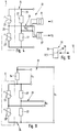
- a position determining device 4 is arranged on the two bodies 1, 2, the structure of which is shown in detail in FIG. 2. It enables the detection of certain relative positions between the two bodies 1, 2.
- the position determination device 4 comprises a sensor 5, which is attached to the first body 1 via a holder 9 is. Furthermore, the position determination device 4 comprises a plurality of indicators 6, 6 ′, which interact with the sensor 5 and are arranged on the second body 2. The arrangement is such that the indicators 6, 6 'pass the sensor 5 in the immediate vicinity when the second body 2 is displaced.
- the sensor 5 according to the example has two magnetic field-sensitive sensor units 7, 7 '. These are preferably semiconductor sensor units which, in the exemplary embodiment, are formed by so-called field plates. Alternatively, it could also be a so-called Hall generator. The use of magnetoresistive elements would also be conceivable.
- the structure and operation of magnetic field sensitive sensor units is e.g. B. in the article "Magnetic field-sensitive semiconductor position sensors”, reprint from "electronics industry”, issues 5/85 and 6/85, pages 1 to 6, or in the book “Sensors magnetic field semiconductors part 1", data book 1982/83, SIEMENS , Pages 40 to 44, explained, so that further explanations are unnecessary at this point.
- This direction of juxtaposition is as Designates base direction 8, the course of which is indicated in FIGS. 1 and 2 by a dash-dotted line.
- the sensor 5 and the indicators 6, 6 ' are arranged with respect to one another in such a way that the indicators 6, 6' pass the two sensor units 7, 7 'without contact when the second body 2 is moved.
- the sensor 5 is positioned such that the sensor units 7, 7 'face the displacement path 12, 12' of the indicators 6, 6 'indicated by a dash-dotted line in FIGS.
- the indicators 6, 6 'thus run past the front 13 of the sensor 5 at a distance, in the area of which the sensor units 7, 7' are located.
- the construction of the sensor 5 according to the example can correspond to that on page 44 of the mentioned publication "Sensors Magnetic Field Semiconductors Part 1". Accordingly, the sensor units 7, 7 'are plate-shaped elements, the plate planes of which run parallel to one another and preferably lie in a common plane. The displacement path 12, 12 'extends parallel to this plane.
- the sensor units 7, 7 'designed as field plates in the exemplary embodiment are each glued onto an insulated surface of a pole shoe 14 made of iron. Towards the shift path 12, 12 ' Plate surfaces of the sensor units 7, 7 'made of semiconductor material can be glued on (not shown) soft iron pole plates, which protect the two field plate systems 7, 7' from mechanical damage.
- a respective sensor unit 7, 7 'with the associated pole piece 14 can be embedded in a magnetically permeable sheath 15. Furthermore, in the exemplary embodiment, these parts are attached to a permanent magnet piece 16 with polarization expediently oriented at right angles to the plate plane. This permanent magnet causes a magnetic field 17, indicated by dash-dotted lines in FIG. 2, which passes through the two sensor units 7, 7 ', in particular at right angles to their plate surfaces. This magnetic field 17 radiates beyond the front side 13 of the sensor 5.
- the distance of the sensor 5 from the displacement path 12, 12 ' is selected such that the indicators 6, 6' run through the magnetic field 17 when the second body 2 is moved.
- the directions of movement of the indicators 6, 6 ', which are referred to as working directions 18, are identified in several of the figures by arrows or double arrows. They run parallel to the direction of displacement 3.
- the indicators 6, 6 'in the exemplary embodiment consist of a ferromagnetic material and preferably of simple steel. When passing through the magnetic field 17, they cause a change in the magnetic field, which results in a change in resistance of the sensor units 7, 7 ′ designed as field plates. From this 22 control signals S1, S2 are derived in an evaluation device to be described (Fig. 4), which can be further used. For example, the drive device acting on the second body 2 can thus be controlled in order to control the movement sequences thereof as a function of specific positions of the second body 2.
- a particular advantage of the position determination device 4 results from the fact that the sensor 5 is aligned with respect to the indicators 6, 6 'in such a way that the working direction 18 of the indicators 6, 6' runs transverse to the base direction 8.
- the two directions 18, 8 are arranged at right angles to one another, that is to say the working direction 18 is rotated through 90 ° with respect to the base direction 8. This opens up extremely flexible position detection options, with each control signal S1, S2 a certain indicator and thus a certain position of the second body 2 relative to that first body 1 can be assigned.
- An advantageous mode of operation is to interconnect the two sensor units 7, 7 'in a so-called differential circuit, so that the sensor 5 forms a differential sensor.
- the two sensor units 7, 7 ' are shown by their field plate resistance 23, 23' which can be influenced via the indicators 6, 6 '. They are integrated in a bridge circuit 24, in the present case forming the two bridge elements of the first bridge branch 25 connected in series.
- the parallel second bridge branch 26 contains two bridge resistors 27 connected in series as the bridge elements.
- the voltage which can be tapped at the bridge transverse branch 28 forms an output signal U a which is used in the generation of the control signals S 1, S 2.
- the two indicators 6, 6 ' are now arranged such that they only influence the magnetic field passing through a sensor unit 7, 7' when passing the sensor 5.
- One indicator 6 thus acts only on the first sensor unit 7, while the other indicator 6 'acts exclusively on the second sensor unit 7'.
- the output signal U a is a positive voltage and the other time a negative voltage.
- the output signal U a is expediently fed to two comparators 31, 31 'with different threshold voltages, so that a control signal S 1 or S 2 is produced as a function of the exciting indicator 6, 6'.
- the preset degree of coverage that is, the degree of coverage of the two sensor units 7, 7 'by an indicator 6, 6' passing them, a signal which is characteristic of a respective degree of coverage can be generated, so that one sensor and several , indicators arranged in different positions has diverse and flexible positioning options.
- the sensor units 7, 7 ' are temporarily covered to a certain degree by the indicators 6, 6' as they pass by.
- overlap is understood to mean all states in which an indicator 6, 6 'passing the sensor 5 influences the magnetic field 17 to a relevant extent, with a respective indicator 6, 6' also definitely being to the side of the sensor units 7, 7 '. can walk past.
- the indicators with a different degree of coverage are referred to as "indicator types".
- indicator types two types of indicators are thus present.
- the indicators 6, 6 ' are preferably adjustable in the assigned working direction 18 with respect to the second body 2 carrying them. This allows a variable specification of the desired switching time.
- two fastening grooves or ribs 32 running parallel to and at a distance from one another and in the direction of displacement 3 are provided on the second body 2, on each of which at least one indicator 6, 6 'is mounted such that it can be adjusted in the longitudinal direction and in can set any desired position immovably.
- fastening grooves or ribs 32 can also have a curved course, in particular when detecting two bodies which execute a swiveling or rotating movement relative to one another.
- the senor 5 is arranged immovably on the first body.
- an adjustable assembly here.
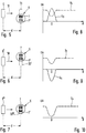
- FIGS. 5, 6 and 7 show an arrangement in which a sensor 5 cooperates with three indicators 6, 6 ', 6' 'of different indicator types. These three indicators 6, 6 ', 6' 'cover the sensor units 7, 7' to different degrees when passing the sensor 5.
- the positions 33, 33 ', 33' 'shown in dash-dot lines in FIGS. 5, 6 and 7 show a respective indicator 6, 6', 6 '' in the position currently opposite the sensor 5, which is referred to as the actuation position.
- “D” denotes the distance between an indicator 6, 6 ', 6' 'approaching the sensor 5 and its actuation position 33, 33', 33 ''.
- FIG. 11 in turn shows the sensor 5 linked to an evaluation device 22. Apart from a series resistor 44, which is connected in series with the bridge circuit 24, the structure corresponds to the evaluation circuit shown in FIG. 4. In addition to the output signal U a , the voltage drop U V across the series resistor 34 is detected here and is included in the determination of the relevant control signal.
- the first indicator 6 according to FIG. 5 is arranged in such a way that, in the actuating position 33, it completely covers the first sensor unit 7 in particular.
- the second sensor device 7 'remains uncovered. Due to the differential circuit, the curve shown in the diagram of FIG. 8 results for the output signal U a with a positive voltage swing when passing through the actuation position 33.
- the second indicator 6 ' is arranged in such a way that, in the actuating position 33', it completely covers only the second sensor unit 7 ', while here the first sensor unit 7 remains unaffected.
- the result for the output signal U a is the curve shown in solid lines in FIG. 9 with a negative voltage swing when passing through the switching position.
- the output signals U a can be evaluated in the evaluation device.
- two comparators with a positive and a negative threshold voltage are sufficient.
- the voltage drop U V is also shown in dashed lines in the diagrams according to FIGS. 8 and 9, but this drop is not necessarily to be used for determining the first and second actuation positions 33, 33 '.
- this drop is used to detect the third actuation position 33 ′′, which is characterized in that the second indicator 6 '' simultaneously covers both sensor units 7, 7 ', preferably completely. If the sensor units 7, 7 'are ideally precisely aligned, there will hardly be a voltage swing as the output signal U a due to the differential principle.
- the indicators of different indicator types With a correspondingly different design of the indicators of different indicator types, it would be readily possible to provide only a single fastening groove or rib 32 on which all indicators are arranged. In favor of a uniform and rational production, however, a uniform outer geometric design of different indicator types should be aimed for. For this purpose, it is advisable to provide the indicators as a specific component of a base body 35 having uniform external dimensions, as is indicated in FIG. 12.
- the base body 35 is composed here of two adjacent sections 36, 37, of which one section 37 forms the indicator 6. This base body 35 can be moved over a sensor 5 in the manner explained in FIG. 7, so that both sensor units 7, 7 'overlap at the same time will. The effect achieved is, however, that of FIG.
- the base body 35 can be a multi-part body, wherein the individual body sections consist of separate material parts that have been put together to form the base body 35.
- a first indicator 6 or a second indicator 6 'according to FIGS. 5 and 6 can be realized with such a base body 35 only by changing the installation position by 180 °.
- At least three indicator types should be present. If these are arranged in a type sequence 1 - 2 - 3 - 1 - 2 - 3 - 1 ..., a clear statement can be made about the direction of movement of the sensor or the indicators based on the always different neighboring indicators.
- a respective indicator can be an additional part attached to the associated body, for example a cam-like or block-like part, as shown in FIGS. 1 and 2.
- the indicators could also be part of a part of the movement to be controlled Be formed body, for example the teeth of a gear.
- the position determining device can be used particularly advantageously in connection with linear, rotary and rotary drives.
- the displacement path 12, 12 ' which determines the working directions 18 therefore does not necessarily have to be linear, but in particular can also have a circular arc shape.
- the position determining device according to the invention can be used extremely flexibly and enables the relatively simple solution even to complex automation problems.
Landscapes
- Physics & Mathematics (AREA)
- General Physics & Mathematics (AREA)
- Measurement Of Length, Angles, Or The Like Using Electric Or Magnetic Means (AREA)
- Length Measuring Devices With Unspecified Measuring Means (AREA)
Applications Claiming Priority (2)
| Application Number | Priority Date | Filing Date | Title |
|---|---|---|---|
| DE4432827A DE4432827C2 (de) | 1994-09-15 | 1994-09-15 | Positionsbestimmungseinrichtung |
| DE4432827 | 1994-09-15 |
Publications (3)
| Publication Number | Publication Date |
|---|---|
| EP0702203A2 true EP0702203A2 (fr) | 1996-03-20 |
| EP0702203A3 EP0702203A3 (fr) | 1998-11-04 |
| EP0702203B1 EP0702203B1 (fr) | 2003-11-12 |
Family
ID=6528265
Family Applications (1)
| Application Number | Title | Priority Date | Filing Date |
|---|---|---|---|
| EP95111286A Expired - Lifetime EP0702203B1 (fr) | 1994-09-15 | 1995-07-19 | Enregistrement de position avec deux capteurs de champ magnétique arrangés côtè à côtè |
Country Status (2)
| Country | Link |
|---|---|
| EP (1) | EP0702203B1 (fr) |
| DE (2) | DE4432827C2 (fr) |
Cited By (1)
| Publication number | Priority date | Publication date | Assignee | Title |
|---|---|---|---|---|
| EP0957343A1 (fr) * | 1998-05-15 | 1999-11-17 | Kabushiki Kaisha Tokai Rika Denki Seisakusho | Détecteur de rotation |
Families Citing this family (3)
| Publication number | Priority date | Publication date | Assignee | Title |
|---|---|---|---|---|
| DE19803018C2 (de) * | 1997-03-05 | 2000-09-07 | Vs Sensorik Gmbh | Magnetischer Meßwertaufnehmer |
| DE19757116C2 (de) * | 1997-12-20 | 2001-02-22 | Daimler Chrysler Ag | Anordnung mit magnetischem Maßstab |
| DE10024850C2 (de) * | 2000-05-19 | 2003-01-23 | Deutsch Zentr Luft & Raumfahrt | Messanordnung, Messkopf und Verfahren zur Herstellung eines Messkopfes |
Family Cites Families (11)
| Publication number | Priority date | Publication date | Assignee | Title |
|---|---|---|---|---|
| US4616281A (en) * | 1982-03-10 | 1986-10-07 | Copal Company Limited | Displacement detecting apparatus comprising magnetoresistive elements |
| DE3214794C2 (de) * | 1982-04-21 | 1984-06-07 | Dr. Johannes Heidenhain Gmbh, 8225 Traunreut | Magnetische Längen- oder Winkelmeßeinrichtung |
| DE3245357C2 (de) * | 1982-12-08 | 1985-02-14 | Dr. Johannes Heidenhain Gmbh, 8225 Traunreut | Inkrementale Meßeinrichtung |
| DE3447325A1 (de) * | 1984-12-24 | 1986-06-26 | Standard Elektrik Lorenz Ag | Positionsgeber |
| DE9010114U1 (de) * | 1990-07-03 | 1990-09-06 | Festo KG, 7300 Esslingen | Arbeitszylinder |
| DE4037545C2 (de) * | 1990-11-26 | 1994-03-17 | Heidenhain Gmbh Dr Johannes | Meßeinrichtung |
| DE4038674A1 (de) * | 1990-12-04 | 1992-06-11 | Automata Gmbh Ind & Robotic Co | Vorrichtung zum bestimmen der absoluten ist-position eines entlang einer vorbestimmten wegstrecke bewegbaren bauteils |
| FR2670888B1 (fr) * | 1990-12-19 | 1994-05-27 | Aerospatiale | Capteur de position angulaire a magnetoresistances. |
| EP0496918A1 (fr) * | 1991-01-31 | 1992-08-05 | Siemens Aktiengesellschaft | Arrangement pour générer des signaux d'impulsions lors du passage de marques sur une pièce |
| DE4129576C2 (de) * | 1991-09-06 | 2001-05-31 | Mueller Arnold Gmbh Co Kg | Magnetisches Meßsystem zur Drehwinkelmessung |
| ES2084870T3 (es) * | 1992-05-15 | 1996-05-16 | Siemens Ag | Disposicion para la deteccion sin contacto del numero de revoluciones o posicion de una parte de transmisor giratoria. |
-
1994
- 1994-09-15 DE DE4432827A patent/DE4432827C2/de not_active Expired - Fee Related
-
1995
- 1995-07-19 EP EP95111286A patent/EP0702203B1/fr not_active Expired - Lifetime
- 1995-07-19 DE DE59510825T patent/DE59510825D1/de not_active Expired - Fee Related
Non-Patent Citations (2)
| Title |
|---|
| "Magnetfeldempfindliche Halbleiter-Positionssensoren", ELEKTRONIK INDUSTRIE, no. 5/6, 1985, pages 1 - 6 |
| "Sensoren Magnetfeldhalbleiter", part 1 SIEMENS, pages: 40 - 44 |
Cited By (2)
| Publication number | Priority date | Publication date | Assignee | Title |
|---|---|---|---|---|
| EP0957343A1 (fr) * | 1998-05-15 | 1999-11-17 | Kabushiki Kaisha Tokai Rika Denki Seisakusho | Détecteur de rotation |
| US6271663B1 (en) | 1998-05-15 | 2001-08-07 | Kabushki Kaisha Tokai Rika Denki Seisakusho | Rotation detector operable to measure magnetism direction change |
Also Published As
| Publication number | Publication date |
|---|---|
| EP0702203A3 (fr) | 1998-11-04 |
| DE4432827C2 (de) | 1998-10-22 |
| EP0702203B1 (fr) | 2003-11-12 |
| DE4432827A1 (de) | 1996-03-28 |
| DE59510825D1 (de) | 2003-12-18 |
Similar Documents
| Publication | Publication Date | Title |
|---|---|---|
| DE3311204C2 (fr) | ||
| DE2558956C2 (fr) | ||
| DE4408623A1 (de) | Magnetischer Positionssensor | |
| DE19533964A1 (de) | Magnetismuserfassungsvorrichtung, die zur Unterdrückung von Schwankungen von Impulssignal-Intervallen in der Lage ist | |
| WO1998021552A1 (fr) | Systemes pour detecter un mouvement rotatif ou translatoire | |
| DE10139154A1 (de) | Winkelstellungssensor | |
| EP2515191A2 (fr) | Machine avec des articulations pivotantes les unes par rapport aux autres | |
| DD257178A3 (de) | Anordnung zur erzeugung von steuersignalen | |
| DE69916017T2 (de) | Magnetoresistiver sensor zur messung der relativen lageveränderung zwischen zwei bauteilen | |
| EP0181415B1 (fr) | Dispositif de positionnement pour vérin sans tige | |
| EP1770373A1 (fr) | Dispositif de mesure de la position absolue | |
| DE102008059774A1 (de) | Magnetischer Encoder | |
| EP0702203B1 (fr) | Enregistrement de position avec deux capteurs de champ magnétique arrangés côtè à côtè | |
| DE10153915B4 (de) | Verfahren und Vorrichtung zur Fassung der Ist-Stellung eines zu lenkenden Rades bei einem Flurförderzeug mit einer elektrischen Lenkung | |
| EP0268030A2 (fr) | Potentiomètre respectivement résistance variable | |
| DE102005061347A1 (de) | Anordnung zur Messung des absoluten Drehwinkels einer Welle | |
| DE3942811A1 (de) | Handrad mit taktiler rastung | |
| DE2230853C3 (de) | Linienschreiber | |
| DE19947483B4 (de) | Kraftfahrzeug-Türschloss | |
| DE60034471T2 (de) | Elektronisches lenksäulenmodul | |
| EP1028516B1 (fr) | Moteur synchrone avec détection de la position du rotor | |
| DE102005025417A1 (de) | Lagegeber | |
| DE3109911C1 (de) | Kapazitiver Signalgeber | |
| DE4035189A1 (de) | Vorrichtung zur drehwinkelpositionierung einer mit exzenterorganen versehenen welle | |
| DE10002731A1 (de) | Stellungssensorschalter |
Legal Events
| Date | Code | Title | Description |
|---|---|---|---|
| PUAI | Public reference made under article 153(3) epc to a published international application that has entered the european phase |
Free format text: ORIGINAL CODE: 0009012 |
|
| AK | Designated contracting states |
Kind code of ref document: A2 Designated state(s): CH DE FR GB IT LI NL |
|
| RAP1 | Party data changed (applicant data changed or rights of an application transferred) |
Owner name: FESTO AG & CO |
|
| PUAL | Search report despatched |
Free format text: ORIGINAL CODE: 0009013 |
|
| AK | Designated contracting states |
Kind code of ref document: A3 Designated state(s): CH DE FR GB IT LI NL |
|
| 17P | Request for examination filed |
Effective date: 19981019 |
|
| 17Q | First examination report despatched |
Effective date: 20010913 |
|
| GRAH | Despatch of communication of intention to grant a patent |
Free format text: ORIGINAL CODE: EPIDOS IGRA |
|
| RTI1 | Title (correction) |
Free format text: POSITION RECORDING WITH TWO MAGNETIC FIELD SENSORS ARRANGED SIDE BY SIDE |
|
| RTI1 | Title (correction) |
Free format text: POSITION RECORDING WITH TWO MAGNETIC FIELD SENSORS ARRANGED SIDE BY SIDE |
|
| GRAS | Grant fee paid |
Free format text: ORIGINAL CODE: EPIDOSNIGR3 |
|
| GRAA | (expected) grant |
Free format text: ORIGINAL CODE: 0009210 |
|
| AK | Designated contracting states |
Kind code of ref document: B1 Designated state(s): CH DE FR GB IT LI NL |
|
| PG25 | Lapsed in a contracting state [announced via postgrant information from national office to epo] |
Ref country code: NL Free format text: LAPSE BECAUSE OF FAILURE TO SUBMIT A TRANSLATION OF THE DESCRIPTION OR TO PAY THE FEE WITHIN THE PRESCRIBED TIME-LIMIT Effective date: 20031112 Ref country code: IT Free format text: LAPSE BECAUSE OF FAILURE TO SUBMIT A TRANSLATION OF THE DESCRIPTION OR TO PAY THE FEE WITHIN THE PRESCRIBED TIME-LIMIT;WARNING: LAPSES OF ITALIAN PATENTS WITH EFFECTIVE DATE BEFORE 2007 MAY HAVE OCCURRED AT ANY TIME BEFORE 2007. THE CORRECT EFFECTIVE DATE MAY BE DIFFERENT FROM THE ONE RECORDED. Effective date: 20031112 Ref country code: GB Free format text: LAPSE BECAUSE OF FAILURE TO SUBMIT A TRANSLATION OF THE DESCRIPTION OR TO PAY THE FEE WITHIN THE PRESCRIBED TIME-LIMIT Effective date: 20031112 Ref country code: FR Free format text: LAPSE BECAUSE OF FAILURE TO SUBMIT A TRANSLATION OF THE DESCRIPTION OR TO PAY THE FEE WITHIN THE PRESCRIBED TIME-LIMIT Effective date: 20031112 |
|
| REG | Reference to a national code |
Ref country code: GB Ref legal event code: FG4D Free format text: NOT ENGLISH |
|
| REG | Reference to a national code |
Ref country code: CH Ref legal event code: EP |
|
| REF | Corresponds to: |
Ref document number: 59510825 Country of ref document: DE Date of ref document: 20031218 Kind code of ref document: P |
|
| NLV1 | Nl: lapsed or annulled due to failure to fulfill the requirements of art. 29p and 29m of the patents act | ||
| GBV | Gb: ep patent (uk) treated as always having been void in accordance with gb section 77(7)/1977 [no translation filed] |
Effective date: 20031112 |
|
| PGFP | Annual fee paid to national office [announced via postgrant information from national office to epo] |
Ref country code: DE Payment date: 20040717 Year of fee payment: 10 |
|
| PG25 | Lapsed in a contracting state [announced via postgrant information from national office to epo] |
Ref country code: LI Free format text: LAPSE BECAUSE OF NON-PAYMENT OF DUE FEES Effective date: 20040731 Ref country code: CH Free format text: LAPSE BECAUSE OF NON-PAYMENT OF DUE FEES Effective date: 20040731 |
|
| PLBE | No opposition filed within time limit |
Free format text: ORIGINAL CODE: 0009261 |
|
| STAA | Information on the status of an ep patent application or granted ep patent |
Free format text: STATUS: NO OPPOSITION FILED WITHIN TIME LIMIT |
|
| 26N | No opposition filed |
Effective date: 20040813 |
|
| EN | Fr: translation not filed | ||
| REG | Reference to a national code |
Ref country code: CH Ref legal event code: PL |
|
| PG25 | Lapsed in a contracting state [announced via postgrant information from national office to epo] |
Ref country code: DE Free format text: LAPSE BECAUSE OF NON-PAYMENT OF DUE FEES Effective date: 20060201 |