EP0702229B1 - Sauerstoffsensor - Google Patents
Sauerstoffsensor Download PDFInfo
- Publication number
- EP0702229B1 EP0702229B1 EP95114546A EP95114546A EP0702229B1 EP 0702229 B1 EP0702229 B1 EP 0702229B1 EP 95114546 A EP95114546 A EP 95114546A EP 95114546 A EP95114546 A EP 95114546A EP 0702229 B1 EP0702229 B1 EP 0702229B1
- Authority
- EP
- European Patent Office
- Prior art keywords
- stopper
- lead
- solid electrolyte
- oxygen sensor
- electrolyte tube
- Prior art date
- Legal status (The legal status is an assumption and is not a legal conclusion. Google has not performed a legal analysis and makes no representation as to the accuracy of the status listed.)
- Expired - Lifetime
Links
Images




Classifications
-
- G—PHYSICS
- G01—MEASURING; TESTING
- G01N—INVESTIGATING OR ANALYSING MATERIALS BY DETERMINING THEIR CHEMICAL OR PHYSICAL PROPERTIES
- G01N27/00—Investigating or analysing materials by the use of electric, electrochemical, or magnetic means
- G01N27/26—Investigating or analysing materials by the use of electric, electrochemical, or magnetic means by investigating electrochemical variables; by using electrolysis or electrophoresis
- G01N27/403—Cells and electrode assemblies
- G01N27/406—Cells and probes with solid electrolytes
- G01N27/407—Cells and probes with solid electrolytes for investigating or analysing gases
- G01N27/4078—Means for sealing the sensor element in a housing
-
- G—PHYSICS
- G01—MEASURING; TESTING
- G01N—INVESTIGATING OR ANALYSING MATERIALS BY DETERMINING THEIR CHEMICAL OR PHYSICAL PROPERTIES
- G01N27/00—Investigating or analysing materials by the use of electric, electrochemical, or magnetic means
- G01N27/26—Investigating or analysing materials by the use of electric, electrochemical, or magnetic means by investigating electrochemical variables; by using electrolysis or electrophoresis
- G01N27/403—Cells and electrode assemblies
- G01N27/406—Cells and probes with solid electrolytes
- G01N27/4062—Electrical connectors associated therewith
-
- G—PHYSICS
- G01—MEASURING; TESTING
- G01N—INVESTIGATING OR ANALYSING MATERIALS BY DETERMINING THEIR CHEMICAL OR PHYSICAL PROPERTIES
- G01N27/00—Investigating or analysing materials by the use of electric, electrochemical, or magnetic means
- G01N27/26—Investigating or analysing materials by the use of electric, electrochemical, or magnetic means by investigating electrochemical variables; by using electrolysis or electrophoresis
- G01N27/403—Cells and electrode assemblies
- G01N27/406—Cells and probes with solid electrolytes
- G01N27/407—Cells and probes with solid electrolytes for investigating or analysing gases
Definitions
- the present invention relates to an oxygen sensor which is used, for example, for detecting an oxygen content in the exhaust gases emitted from an internal combustion engine.
- An oxygen sensor of this kind is made up or an oxygen content detecting element having a tubular shape with one end closed and made of solid electrolyte and a metallic housing assembly including a metal shell for holding the element thereon.
- the oxygen sensor is installed on an exhaust pipe of an internal combustion engine by way of the metal shell to bring an electrode layer (i.e., reference electrode layer) on the inner surface of the element in contact with a reference oxygen gas (i.e., atmospheric air) and an electrode layer (i.e., measurement electrode layer) on the outer surface of the element in contact with the exhaust gases and is adapted to cause an electromotive force (i.e., potential difference) between the electrodes in accordance with the difference of the oxygen content between the inner and outer surfaces of the element and output a signal representative of the electromotive force to a control circuit for thereby detecting the oxygen content in the exhaust gases and controlling the same.
- an electromotive force i.e., potential difference
- the electrode layers formed on the inner and outer surfaces of the element of the oxygen sensor are connected by way of metallic leads to an output lead wire for connection to a control circuit and a grounding lead wire.
- the metallic leads have at one end thereof electrode connecting portions having a spring property. The electrode connecting portions are pushed axially of the element to fit in and on the element and held in contact with the lead layers under spring pressure.
- the metallic leads are connected at another end thereof to lead wires.
- Fig. 13 shows a prior art oxygen sensor of the type utilizing metallic leads for connection between lead layers and lead wires.
- a metallic lead 51 is employed for connection between a lead layer 14 connected to an electrode layer on the inner surface of an oxygen content detecting element 3 and an output lead wire 12.
- the metallic lead 51 is constructed as shown in Fig. 14 and is formed from a metal plate having a spring property.
- the metallic lead 51 has an electrode connecting portion 52 at one end or lower end thereof.
- the electrode connecting portion 52 is formed into a tubular shape having a part-circular cross section.
- the electrode connecting portion 52 has, in an unloaded or unstressed state, an outer diameter which is a little larger than the inner diameter of the tubular lead layer 14 formed on the inner surface of the element 3.
- the metallic lead 51 further has a nearly vertical intermediate or stem portion 53 and a crimp-style terminal portion 54 of a U-like cross section at another end or upper end thereof.
- the crimp-style terminal portion 54 is provided for connection to lead wires.
- the intermediate portion 53 is provided between the electrode connecting portion 52 and the crimp-style terminal portion 54 for interconnecting therebetween.
- the electrode connecting portion 52 has a smaller diameter lower end portion for forming a ceramic heater gripping portion 55 of a part-circular cross section.
- the ceramic heater gripping portion 55 is smaller in diameter than the electrode connecting portion 52 and adapted to grip or hold a ceramic heater 18 under spring pressure.
- the ceramic heater gripping portion 55 has, in its unloaded or unstressed state, an inner diameter smaller than the outer diameter of the ceramic heater 18.
- the crimp-style terminal portion 54 is connected by crimping to an end portion 12a of a lead wire 12 extending through a sealing member 16, and the ceramic heater gripping portion 55 grips a heater 18.
- the electrode connecting portion 52 is pushed axially into the element 3 and brought in contact with the inner lead layer 14 under spring pressure or by spring force.
- 61 in Fig. 13 is an insulator made of a ceramic material, or the like and has a tubular shape or hollow cylindrical shape.
- the insulator 61 is arranged in contact with the bottom surface of the seal member 16 and has through holes consisting of smaller diameter through hole sections 62 aligned with respective through holes 16b of the seal member 16 and lower larger diameter through hole sections 63.
- the insulator 61 insulates the crimp-style terminal portion 54 of the metallic lead 51 from a crimp-style terminal portion 74 of a metallic lead 71 and metallic housing inner and outer tubes 64 and 65.
- the metallic leads 71 is provided for connection between a lead layer 15 connected to an electrode layer on the outer surface of the element 3 and a grounding lead wire 13.
- the metallic lead 71 is constructed as shown in Fig. 15 and basically similar to the above described output metallic lead 51. That is, the metallic lead 71 is formed from a metal plate having a spring property and has an electrode connecting portion 72 at one or lower end thereof.
- the electrode connecting portion 72 is formed into a tubular shape having a part-circular cross section.
- the electrode connecting portion 72 has, in an unloaded or unstressed condition, an inner diameter smaller than the outer diameter of the tubular lead layer 15 formed on the outer surface of the element 3.
- the metallic lead 71 further has an intermediate or stem portion 73 and a crimp-style terminal portion 74 of a U-like cross section.
- the crimp-style terminal portion 74 is provided for connecting to the grounding lead wire 13 extending through the seal member 16.
- the intermediate portion 73 is provided between the electrode connecting portion 72 and the crimp-style terminal portion 74 for interconnecting therebetween.
- the electrode connecting portion 72 Under the condition of the crimp-style terminal portion 74 being connected to the inner end 13a of the grounding lead wire 13, the electrode connecting portion 72 is pushed axially of the element 3 to fit on the element 3 and is brought in contact with the lead layer 15 under spring pressure.
- the lead wires 12 and 13 may possibly be subjected to a tensile force even after installation of the sensor on an exhaust pipe for various reasons.
- the seal member 16 is thus required to not only sealingly surround the lead wires and but fixedly hold the lead wires.
- the force exerted by the seal member for fixedly holding the lead wires is not sufficiently large.
- the insulator 61 is provided in contact with the seal member 16, such an insulator 61 can scarcely exert a force for obstructing axial movement of the lead wires.
- the above described prior art oxygen sensor has a possibility that when the lead wires 12 and 13 are pulled outward by a relatively large force, the electrode connecting portions 52 and 72 connected to the inner and outer surface lead layers 14 and 15 of the element 3 are moved upward of the respective lead layers 14 and 15 as shown by the two-dot chain lines in Fig. 13 or may be separated from the element 3 in case the force is excessively large.
- the above described prior art oxygen sensor has a problem on the reliability and durability, i.e., a problem that unstable electrical connection and unstable outputting may occur or malfunction may occur due to disconnection by the separation, thus disabling accurate detection and control of oxygen content in the exhaust gases.
- US 4, 923, 587 discloses a terminal fixing structure which includes a cylindrical ceramic base with a conductive contact on the side and a metal thermal with a pair of resilient arms for holding the side of the ceramic base and for contacting the conductive contact.
- Said terminal fixing structure can be used in a oxygen sensor.
- US 5, 329, 806 describes an exhaust oxygen sensor including a component requiring electricity to operate such as a heater or oxygen electrode.
- US 50, 49, 255 discloses an oxygen sensing unit comprising an oxygen sensing cell with a closed outer end which is encircled by a sidewall of a protective shell or shield.
- an oxygen sensor according to claim 1 or by an oxygen sensor according to claim 6.
- Embodiments of the oxygen sensor according to claim 1 are indicated in subclaims 2 - 5 and embodiments of the oxygen sensor according to claim 6 are indicated in subclaims 7 - 13.
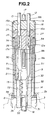
- an oxygen sensor is generally indicated by 1 and shown as being of the type equipped with a ceramic heater, i.e., of the type having four lead wires.
- the oxygen sensor 1 includes a tubular metal shell 2 having a threaded portion 2a for attachment to an exhaust manifold or pipe of an internal combustion engine, and a tubular oxygen content detecting element or solid electrolyte tube 3 with one end closed and another end open.
- the solid electrolyte tube 3 has at a nearly longitudinal center thereof an outward flange 3a which is received inside the metal shell 2.
- the solid electrolyte tube 3 is fixedly attached to the metal shell 2 by interposed therebetween a tubular insulation member 4 made of a ceramic material, a seal member 5 made of powdered talc, a seal pipe 6, packings 7 and 8, and a housing inner tube 9 which cooperates with a housing outer tube 11 to constitute a tubular housing and further with the metal shell 3 to constitute a metallic housing assembly.
- the housing inner tube 9 is disposed at the rear end (i.e. the upper end in Fig. 1) of the metal shell 2 and having a flanged lower end 9a which is fixedly attached to the metal shell 2 by being interposed between the packing 8 and a bent or crimped upper end 2b of the metal shell 2.
- an insulation between the metal shell 2 and the solid electrolyte tube 3 can be attained, together with a seal between the metal shell 2 and the solid electrolyte tube 3 (i.e., between an exhaust gas side and a reference gas side) and a seal between the metal shell 2 and the housing inner tube 9 (i.e., air tight seal or liquid tight seal of the sensor 1).
- a seal between the metal shell 2 and the solid electrolyte tube 3 i.e., between an exhaust gas side and a reference gas side
- a seal between the metal shell 2 and the housing inner tube 9 i.e., air tight seal or liquid tight seal of the sensor 1.
- the solid electrolyte tube 3 is attached to the metal shell 2 in such a manner that the open end thereof is accommodated in the housing assembly constituted by the metal shell 3, housing inner tube 9 and housing outer tube 11.
- 10 is a protective cap attached to the front or lower end of the metal shell 2 for covering a portion of the solid electrolyte tube 3 protruding from the metallic housing assembly for thereby protecting the solid electrolyte tube 3.
- the housing outer tube 11 is fitted on the upper end portion of the housing inner tube 9 to constitute the above described housing.
- An output lead wire 12 and a grounding lead wire 13 have inner ends disposed inside the housing and connected to an inner surface lead layer 14 and an outer surface lead layer 15 by way of the same metallic leads 51 and 71 as those shown in Figs. 14 and 15.
- the lead layers 14 and 15 are formed on the inner and outer surfaces of the solid electrolyte tube 3 at a location adjacent the open end of the solid electrolyte tube 3.
- the lead layers 14 and 15 are connected to electrode layers 3b and 3c which are formed on the inner and outer surfaces of the solid electrolyte tube 3, respectively.
- the metallic leads 51 and 71 have at one end thereof electrode connecting portions 52 and 72 for connection to the inner surface lead layer 14 and the outer surface lead layer 15 and at another end crimp-style terminal portions 54 and 74 for connecting to the lead wires 12 and 13.
- the electrode connecting portions 52 and 72 are respectively pushed against the open end of the solid electrolyte tube 3 and fitted in and on the inner surface lead layer 14 and the outer surface lead layer 15 of the solid electrolyte tube 3 in such a manner that upper end faces 52a and 72a of the electrode connecting portions 52 and 72 are flush with the face of the open end or upper end of the solid electrolyte tube 3.
- the lead wires 12 and 13 have inner ends 12a and 13a which are disposed inside of the housing and connected to the crimp-style terminal portions 54 and 74 of the metallic leads 51 and 71.
- the lead wires 12 and 13 extend outward of the housing through a seal member 16 whilst being sealingly held by the seal member 16.
- indicated by 17 is a pair of lead wires, though only one is shown in Fig. 1, which is connected to a ceramic heater 18 for heating the solid electrolyte tube 3.
- the lead wires 17 extend outward of the housing through the seal member 16 whilst being sealingly held by the seal member 16.
- the seal member 16 is attached to the upper end of the housing outer tube 11 to sealingly close the same.
- the seal member 16 is in the form of a disc and has a recess 16a at a nearly central portion of its bottom.
- the seal member 16 has four axial through holes 16b for allowing passage of the lead wires 12, 13 and 17 therethrough.
- the through holes 16b are arranged in a circular array with equal intervals. It is desirable to form the seal member 16 of a fluorine resin having a high heat resistant property.
- the seal member 16 is made of PFA (tetrafluoroethylene-perfluoroalkyvinylester).
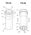
- the stopper 21 has a hollow cylindrical body 30 hanging from a lower end of a separator 22. That is, the stopper 21 in this embodiment is formed integral with the separator 22 to constitute a single piece.
- the portion above the two-dot chain line represents the separator 22.
- the separator 22 is similar to that of the above described prior art oxygen sensor and made of a ceramic material.
- the separator 22 has an upper end 24 fittingly engaged in the recessed bottom of the seal member 16.
- the separator 22 is in the form of a disc and adapted to fit at an upper end 24 in the recess 16a of the seal member 16.
- the separator 22 has four stepped through holes axially aligned with the through holes 16b of the seal member 16 and including upper smaller diameter through hole sections 25 and lower larger diameter through hole sections 26.
- the larger diameter through hole sections 26 are adapted to accommodate therewithin the crimp-style terminal portions 54 and 74 of the metallic leads 51 and 71 to connect thereto the inner ends 12a and 13a of the lead wires 12 and 13, respectively.
- the separator 22 has at a location adjacent the upper end thereof an outward flange 27 having an upper end face 28 brought into abutting engagement with the bottom face of the seal member 16.
- the separator 22 has at a location axially under the flange 27 a hollow cylindrical portion 29 of the same outer diameter as the hollow cylindrical body 30.
- the stopper 21 has a lower end face 23 in abutting engagement with the upper end faces 52a and 72a of the electrode connecting portions 52 and 72 of the metallic leads, i.e., in abutting engagement with the face of the open end of the solid electrolyte tube 3.
- the stopper 21 further has a through hole consisting of axial hole sections 32 larger in diameter than the through hole sections 26 and axially aligned with the same, respectively and a center hole section 33 concentric with the hollow cylindrical body 30.
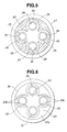
- the stopper 21 of this embodiment has at the lower end thereof a cross section including a four-cusped figure-like opening including a central opening section 33 for disposition of the ceramic heater 18, a four-cusped figure section for disposition of the metallic leads 51 and 71 connected to the lead layers 14 and 15 and the metallic leads 18b connected to the ceramic heater 18, a radially outer peripheral portion 23a for abutting engagement with the axial end face 72a of the electrode connecting portion 72 fitted on the open end of the solid electrolyte tube 3, and four radially inwardly protruded portions 23b for abutting engagement with the end face 52a of the electrode connecting portion 52 fitted in the open end of the solid electrolyte tube 3.
- the oxygen sensor 1 when the lead wires 12 and 13 are pulled to subject the electrode connecting portions 52 and 72 of the metallic leads 51 and 71 to a tensile force so that the electrode connecting portions 52 and 72 are urged for removal or separation from the lead layers 14 and 15, axial movements of the electrode connecting portions 52 and 72 are stopped or blocked by the lower end face 23 of the stopper 21 so that separation or removal of the electrode connecting portions 52 and 72 from the lead layers 14 and 15 is prevented. Furthermore, as shown in Fig.
- the stopper 21 with the hollow cylindrical body 30 is adapted to surround the metallic leads 51 and 71 radially thereof and at a location between the open end of the solid electrolyte tube 3 and the crimp-style terminal portions 54 and 74 of the metallic leads 51 and 71, and the lower end face 23 of the stopper 21 is adapted to be matched with or joined with the open end face of the solid electrolyte tube 3.
- the oxygen sensor 1 can prevent deterioration of the oxygen content detecting ability and corrosion of the inner surface electrode layer 14 and can effect a reliable operation for an elongated period.
- the oxygen sensor 1 is assembled as follows.
- the solid electrolyte tube 3 and the housing inner tube 9 are fixed to the metal shell 2 to prepare a front end side subassembly.
- the ends 12a and 13a of the lead wires 12 and 13 are connected to the inner face and outer face lead layers 14 and 15 of the solid electrolyte tube 3 by way of the metallic leads 51 and 71 in the following manner. That is, the end 12a of the output lead wire 12 is let to pass through the through hole 16b of the seal member 16 and the through holes 25, 26 and 32 of the separator 22 and the stopper 21. The end 12a of the lead wire 12 is then connected by crimping to the crimp-style terminal portion 54 of the metallic lead 51. The ceramic heater 18 is gripped by the heater gripping portion 55.
- the end 13a of the grounding lead wire 13 is let to pass similarly through the through hole 16b of the seal member 16 and the through holes 25, 26 and 32 of the separator 22 and the stopper 21 and is connected by crimping to the crimp-style terminal portion 74 of the metallic lead 71.
- the end portions of a pair of lead wires 17 connected to the ceramic heater 18 are let to pass through the through holes 16b of the seal member 16 and the through holes 25, 26 and 32 of the separator 22 and the stopper 21 and connected by soldering to the connecting terminals 18a of the heater 18 by way of intermediate metallic leads 18b.
- the rear end side subassembly and the front end side subassembly are assembled in such a manner that the housing outer tube 11 is fitted on the housing inner tube 9 and the electrode connecting portions 52 and 72 are pushed axially into and onto the open end of the solid electrolyte tube 3 so as to be brought in contact with the inner face and outer face lead layers 14 and 15 under spring pressure and thereby electrically connected to same.
- the upper end portion of the above described housing outer tube 11 is pressed axially by a predetermined compression force and heated to a predetermined temperature so that the seal member 16 is deformed so as to seal the interface between the lead wires 12, 13 and 15 and the seal member 16, and the lower end portion of the housing outer tube 11 and the inner tube 9 are driven inward so as to reduce in diameter and thus joined together by caulking.
- a packing 34 made of fluororesin is disposed between the lower face of the flange 27 of the separator 22 and the upper end portion of the inner tube 9 to provide a seal therebetween.
- the stopper 21 can transmit a pushing force for pushing the electrode connecting portions 52 and 72 against the respective lead layers 14 and 15, so by previously assembling the seal member 16, the stopper 21 and the metallic leads 51 and 71 into a single unit so that they are inserted into the inner tube 9 all at once, it becomes possible to push the electrode connecting portions 52 and 72 into the respective lead layers 14 and 15 located at the innermost part of the housing inner tube 9 without using a particular jig. Accordingly, the oxygen sensor 1 of this embodiment can effect easier assemblage.
- the stopper 21 is not limited to what has been described and shown in the above embodiment.
- the stopper 21 can be designed to have another shape and structured so long as it is held engaged with the electrode connecting portions 52 and 72 and prevents them from being separated from the lead layers 14 and 15 of the solid electrolyte tube 3 when the lead wires 12 and 13 are pulled outward to subject the metallic leads 51 and 71 to a tensile force.
- slits 35 may be formed in the cylindrical body 30 of the stopper 21 in the above described embodiment with suitable intervals.
- the stopper 21 in Fig. 8 has a plurality of axial slits 35 in such a manner as to allow the four-cusped figure section 32 to open radially outward so that the cross section of the stopper 21 at the lower end thereof consists of four independent solid portions.
- the stopper 21 is formed integral with the separator 22, they can be separated in the place indicated by the two-dot chain line in Fig. 4 so that the separator 22 and the stopper 21 are formed separately from each other as shown in Fig. 9.
- the lower end outer portion of the separator 22 is formed into a stepped shape and the upper end inner circumferential portion of the stopper 21 is stepped correspondingly so that they can be fitted together.
- the stopper 21 and separator 22 are the same as that shown in Fig. 2 so similar reference characters are used to indicate similar parts and portions.
- the oxygen sensor 1 has been described and shown as being of the type having four leads, i.e., a pair of output and grounding lead wires 12 and 13 connected by way of the metallic leads 51 and 71 to the inner surface and outer surface lead layers 14 and 15 and a pair of lead wires 17 for the ceramic heater 18.
- the oxygen sensor can be of the type which is not equipped with any heater, i.e., of the type having two leads, which is constructed so as to dispense with such a ceramic heater 18, intermediate lead 18b, lead wires 17, and the gripping portion 55 of the metallic lead 51 otherwise provided to the above described embodiment.
- the above described seal member 16 needs to be of such a variant that does not have any through holes for the lead wires 17.
- the stopper 21 while such one as shown in Figs. 2, 8 or 9 can be used as it is, it can be of such a variant as for example shown in Fig. 10, i.e., can be of such a variant that has a lower end face (the face for engagement with the electrode connecting portion of each metallic lead) 23 having only four through holes 32.
- the stopper can be of such one that has two through holes 32.
- two-dot chain lines indicate the upper ends of the electrode connecting portions 52 and 72.
- the oxygen sensor can be of the three lead type or of a so-called case grounded type in which the inner surface lead layer 14 of the solid electrolyte tube 3 is electrically connected to the output lead wire 12 for thereby being connected to a control circuit whilst the outer surface electrode layer 15 of the solid electrolyte tube 3 is electrically connected to the metallic housing assembly for thereby being grounded by way of the exhaust pipe.
- the oxygen sensor can be of the type in which the lead layer (normally, outer surface lead layer) connected to one of the inner surface and outer surface electrode layers of the solid electrolyte tube is adapted to be grounded by way of the exhaust pipe and the lead layer connected to the other of the electrode layers is connected to the metallic lead which is in turn connected to the output lead wire.
- the oxygen sensor can be of one lead type which is not equipped with any heater and is connected by only an output lead wire.
- the oxygen sensor of the case ground type is employed and the above described metallic lead is connected to the outer surface output lead layer, it is not necessary, as shown in Fig. 12, for the end face 23 of the stopper 21 to have any radially inwardly protruded portions since the upper end of the electrode connecting portion 72, as indicated by two-dot chain line in Fig. 12, can engage almost at its entirety the lower end of the stopper 21 .
Landscapes
- Chemical & Material Sciences (AREA)
- Life Sciences & Earth Sciences (AREA)
- Health & Medical Sciences (AREA)
- Physics & Mathematics (AREA)
- Chemical Kinetics & Catalysis (AREA)
- Electrochemistry (AREA)
- Molecular Biology (AREA)
- Analytical Chemistry (AREA)
- Biochemistry (AREA)
- General Health & Medical Sciences (AREA)
- General Physics & Mathematics (AREA)
- Immunology (AREA)
- Pathology (AREA)
- Measuring Oxygen Concentration In Cells (AREA)
Claims (13)
- Sauerstoffsensor (1 ) mit:gekennzeichnet durcheiner rohrförmigen Metallschale (2);einem rohrförmigen Gehäuse, verbunden an einem Ende desselben mit der Metallschale (2), um eine Gehäuseanordnung zu bilden;einem Dichtungsteil (16), verbunden mit einem weiteren Ende des rohrförmigen Gehäuses zum abgedichteten Verschließen derselben;einem Festelektrolyt- Rohr (3) mit einem offenen Ende verbunden mit der Metallschale (2) derart, daß das offene Ende innerhalb der Gehäuseanordnung angeordnet ist;Elektrodenschichten (3b), (3c), versehen mit Innen- und Außenflächen des Festelektrolyten (3);einer Leitungsschicht (14), vorgesehen an dem Elektrolytrohr (3) und verbunden einer der Elektrodenschichten (3b), (3c);einem Leitungsdraht (12), der sich durch das Dichtungsteil (16) zwischen Innenseite und Außenseite des Gehäuses erstreckt, während er abgedichtet durch das Dichtungsteil (16) gehalten wird, wobei der Leitungsdraht (12) ein inneres Ende (12a) aufweist, angeordnet innerhalb der Gehäuseanordnung;einer metallischen Leitung 51, angeordnet innerhalb des Gehäuses für eine Verbindung zwischen der Leitungsschicht (12) und dem inneren Ende (12a) des Leitungsdrahtes (12), wobei die metallische Leitung (51) an ihrem einen Ende einen Elektrodenverbindungsabschnitt (52) aufweist, der ein Federeigenschaft hat, wobei der Elektrodenverbindungsabschnitt (52), der mit der Innen- oder Außenoberflächen des Festelektrolyt- Rohres (3) verbunden und unter Federdruck in Kontakt mit der Leitungsschicht (14) gehalten wird
einen Anschlag (21), eingesetzt zwischen dem Dichtungsteil (16) und dem offenen Ende des Festelektrolyt- Rohres (3), wobei der Anschlag (21) hohl ist, um durch ihn hindurch den Durchgang der metallischen Leitung (51) zu gestatten und der ein axiales Ende (23) hat, anliegend im Eingriff mit einer axialen Endfläche (52a) des Elektrodenverbindungsabschnittes (52), um so eine axiale Bewegung des Elektrodenverbindungsabschnittes (52) relativ zu dem Festelektrolyt- Rohres (3) zu verhindern, wenn der Leitungsdraht (12) aus der Gehäuseanordnung herausgezogen wird. - Sauerstoffsensor (1 ) nach Anspruch 1, außerdem aufweisend eine Trennvorrichtung (22), eingesetzt zwischen dem Dichtungsteil (16) und dem Anschlag (21) zum Isolieren eines weiteren Endes der metallischen Leitung (51) relativ zu der Gehäuseanordnung, wobei der Anschlag (21) ist einstückig mit der Trennvorrichtung (22) ausgebildet ist.
- Sauerstoffsensor (1 ) nach Anspruch 1, außerdem aufweisend eine Trennvorrichtung (22), eingesetzt zwischen dem Dichtungsteil (16) und dem Anschlag (21) zum Isolieren eines weiteren Endes der metallischen Leitung (51) relativ zu der Gehäuseanordnung, wobei der Anschlag (21) von der Trennvorrichtung (22) getrennt ausgebildet ist.
- Sauerstoffsensor (1 ) nach Anspruch 1, wobei der Elektrodenverbindungsabschnitt (52) der metallischen Leitung (51) einen teilweise kreisförmigen Querschnitt hat und eine axiale Endefläche plan mit einer Fläche des offenen Endes des Festelektrolyt - Rohres (3), wobei der Anschlag ist zylindrisch ist.
- Sauerstoffsensor (1 ) nach Anspruch 4, wobei der Elektrodenverbindungsabschnitt (52) der metallischen Leitung (51) auf das offene Ende des Festelektrolyt- Rohres (3) aufgesetzt ist, wobei der Anschlag (21) an dem axialen Ende (23) einen Querschnitt hat, der eine vierspitzenfigurenartige Mittelöffnung zum Durchgang der metallischen Leitung (51) hat und einen festen Umfangsabschnittes (23a) für eine Anlage mit der axialen Endfläche des Verbindungsabschnittes (52).
- Sauerstoffsensor (1 ) mit:gekennzeichnet durcheiner rohrförmigen Metallschale (2);-einem rohrförmigen Gehäuse, verbunden mit einem Ende der Metallschale (2), um eine Gehäuseanordnung zu bilden;einem Dichtungsteil (16), verbunden mit einem weiteren Ende des rohrförmigen Gehäuses zum abgedichteten Verschließen desselben;ein Festelektrolyt- Rohr (3) mit einem offenen Ende, verbunden mit der Metall schale (2), derart, daß das offene Ende innerhalb der Gehäuseanordnung angeordnet ist; wobei das Festelektrolyt- Rohr (3), auf seiner Innen und Außenoberfläche Elektrodenschichten (3b), (3c) aufweist und Leitungsschichten (14, 15), jeweils verbunden mit den Elektrodenschichten (3b), (3c);einem Paar von Leitungsdrähten (12, 13), die sich durch das Dichtungsteil (16) zwischen Innenseite und Außenseite des Gehäuses erstrecken, während sie abgedichtet durch das Dichtungsteil (16) gehalten werden, wobei die Leitungsdrähte (12, 13), innere Enden (12a, 13a) haben, die innerhalb der Gehäuseanordnung angeordnet sind;einem Paar von metallischen Leitungen (51, 71), angeordnet innerhalb der Gehäuseanordnung für eine Verbindung zwischen den Leitungsschichten (14, 15) und den inneren Enden (12a, 13a) der Leitungsdrähte (12, 13), wobei die metallischen Leitungen (51, 71) an ihrem einen Ende Elektrodenverbindungsabschnitte (52, 72) haben, die mit der Innen- und Außenflächen des Festelektrolyt- Rohres (3) verbunden und unter Federdruck in Kontakt jeweils mit den Leitungsschichten (14, 15), gehalten sind
einen Anschlag (21), eingesetzt zwischen dem Dichtungsteil (16) und dem offenen Ende des Festelektrolyt- Rohres (3), wobei der Anschlag (21) hohl ist, um durch ihn hindurch den Durchgang der metallischen Leitungen (51, 74) zu gestatten und ein axiales Ende (23) hat, in anliegendem Eingriff mit einer axialen Endfläche der Elektrodenverbindungsabschnitte (52, 72), um so eine axiale Bewegung der Elektrodenverbindungsabschnitte (52, 72), relativ zu dem Festelektrolyt- Rohr (3) zu verhindern, wenn die Leitungsdrähte (12, 13) aus der Gehäuseanordnung herausgezogen werden. - Sauerstoffsensor (1 ) nach Anspruch 6, außerdem aufweisend eine Trennvorrichtung (22), eingesetzt zwischen dem Dichtungsteil (16) und dem Anschlag (21) zum Isolieren eines weiteren Endes jeder der metallischen Leitungen (51, 71), relativ zu der Gehäuseanordnung, wobei der Anschlag (21) einstückig mit der Trennvorrichtung ausgebildet ist.
- Sauerstoffsensor (1 ) nach Anspruch 6, außerdem aufweisend eine Trennvorrichtung (22), eingesetzt zwischen Dichtungsteil (16) und dem Anschlag (21) zum Isolieren eines weiteren Endes jeder der metallischen Leitungen (51, 71), relativ zu der Gehäuseanordnung, wobei der Anschlag (21) getrennt von der Trennvorrichtung (22) ausgebildet ist.
- Sauerstoffsensor (1 ) nach Anspruch 6, wobei jeder der Elektrodenverbindungsabschnitte (52, 72) der metallischen Leitungen (51, 71) einen teilweise kreisförmigen Querschnitt aufweist und eine axiale Endfläche hat, die in Übereinstimmung mit einer Fläche des offenen Endes des Festelektrolyt- Rohres (3) ist, wobei der Anschlag (21) zylindrisch ist.
- Sauerstoffsensor (1 ) nach Anspruch 9, wobei der Anschlag (21) an dem axialen Ende (23) einen Querschitt hat, der zwei kreisförmigen Öffnungen (32) zum Durchgang der metallischen Leitungen (51, 71) aufweist, einen radial inneren, festen Abschnitt zum anliegenden Eingriff mit der axialen Endefläche eines der Elektrodenverbindungsabschnitte (52, 72), eingesetzt in das offene Ende des Festelektrolyt- Rohres (3) und einem radialen äußeren festen Abschnitt (23a) zum anliegenden Eingriff mit der axialen Endfläche des anderen Elektrodenverbindungsabschnittes (52, 72), angepaßt an das offene Ende der festen Elektrolytröhre (3).
- Sauerstoffsensor (1 ) nach Anspruch 6, außerdem aufweisend eine Heizung (18), untergebracht in der Gehäuseanordnung, und ein Paar Leitungsdrähte (17), mit der Heizung (18) verbunden, die sich zwischen Innen- und Außenseite des Gehäuses durch den Anschlag (21) und das Dichtungsteil (16) erstrecken, während sie abgedichtet durch das Dichtungsteil (16) gehalten werden, wobei der Anschlag (21) an dem Ende einen Querschnitt aufweist, der ein vierspitzenfigurartige Öffnung aufweist, enthaltend einen Mittelöffnungsabschnitt (33) zur Anordnung der Heizung (18), eine vierspitzenfigurartige Abschnitt (32) zur Anordnung der Leitungsdrähte (12, 13), verbunden mit den Leitungsschichten (14, 15) und den Leitungsdrähten (17), verbunden mit der Heizung (18), einen radial äußeren Umfangsabschnitt (23a) mit der axialen Endfläche eines der Elektrodenverbindungsabschnitte (52, 72), eingesetzt auf dem offenen Ende des Elektrolytrohres (3), und vier radial nach innen vorspringenden Abschnitten (23b) zur Anlage mit der Endfläche des anderen Elektrodenverbindungsabschnittes (52, 72), eingesetzt auf das offene En de des Festelektrolyt- Rohres (3).
- Sauerstoffsensor (1 ) nach Anspruch 11, wobei der Anschlag (21) eine Mehrzahl von axialen Schlitzen (35) aufweist, derart, daß er dem vierspitzenfigurenartigen Abschnitt (32), der sich radial nach außen öffnet, folgt, so daß der Querschnitt des Anschlags (21) an dem Ende aus vier unabhängigen festen Abschnitten besteht.
- Sauerstoffsensor (1) nach einem der vorhergehenden Ansprüche, wobei der Anschlag (21) aus einem keramischen Material hergestellt ist.
Applications Claiming Priority (3)
| Application Number | Priority Date | Filing Date | Title |
|---|---|---|---|
| JP251305/94 | 1994-09-19 | ||
| JP25130594A JP3522357B2 (ja) | 1994-09-19 | 1994-09-19 | 酸素センサ |
| JP25130594 | 1994-09-19 |
Publications (2)
| Publication Number | Publication Date |
|---|---|
| EP0702229A1 EP0702229A1 (de) | 1996-03-20 |
| EP0702229B1 true EP0702229B1 (de) | 2001-12-19 |
Family
ID=17220836
Family Applications (1)
| Application Number | Title | Priority Date | Filing Date |
|---|---|---|---|
| EP95114546A Expired - Lifetime EP0702229B1 (de) | 1994-09-19 | 1995-09-15 | Sauerstoffsensor |
Country Status (4)
| Country | Link |
|---|---|
| US (1) | US5679226A (de) |
| EP (1) | EP0702229B1 (de) |
| JP (1) | JP3522357B2 (de) |
| DE (1) | DE69524698T2 (de) |
Families Citing this family (31)
| Publication number | Priority date | Publication date | Assignee | Title |
|---|---|---|---|---|
| JP3624526B2 (ja) * | 1995-06-07 | 2005-03-02 | 株式会社デンソー | 酸素濃度検出器 |
| JP3334479B2 (ja) * | 1996-01-25 | 2002-10-15 | 株式会社デンソー | ヒータ付空燃比センサの組付方法 |
| TW338094B (en) * | 1996-05-22 | 1998-08-11 | Toyota Motor Co Ltd | Method and device of burning control of an oxygen sensor |
| JP3027726B2 (ja) * | 1996-06-05 | 2000-04-04 | 日本特殊陶業株式会社 | ヒータ付き酸素センサ |
| JP3873390B2 (ja) * | 1996-09-04 | 2007-01-24 | 株式会社デンソー | 酸素センサー |
| US5817920A (en) * | 1997-03-18 | 1998-10-06 | General Motors Corporation | Oxygen sensor with annular support member providing improved mechanical shock resistance |
| US6039856A (en) * | 1997-04-23 | 2000-03-21 | Robert Bosch Gmbh | Measuring device |
| DE69838524T2 (de) * | 1997-08-29 | 2008-07-03 | Ngk Spark Plug Co., Ltd. | Sauerstoffsensor |
| DE69937774T2 (de) | 1998-08-19 | 2008-12-04 | NGK Spark Plug Co., Ltd., Nagoya-shi | Gassensor |
| JP3662464B2 (ja) * | 1999-06-23 | 2005-06-22 | 日本特殊陶業株式会社 | 酸素センサ |
| ES2154239B1 (es) * | 1999-08-10 | 2001-10-01 | Union Fenosa Generacion S A | Sonda de oxigeno. |
| JP3785319B2 (ja) * | 2000-12-11 | 2006-06-14 | 株式会社日立製作所 | 流量計測装置 |
| JP4560977B2 (ja) * | 2001-03-29 | 2010-10-13 | 株式会社デンソー | ガスセンサの製造方法 |
| JP4047919B2 (ja) * | 2002-07-19 | 2008-02-13 | 日本特殊陶業株式会社 | センサ、センサの製造方法、セパレータと付勢部材の組立体 |
| JP3885789B2 (ja) * | 2002-12-20 | 2007-02-28 | 株式会社デンソー | ガスセンサ |
| JP3885781B2 (ja) * | 2003-08-08 | 2007-02-28 | 株式会社デンソー | ガスセンサ |
| JP2006307834A (ja) * | 2005-03-31 | 2006-11-09 | Ngk Spark Plug Co Ltd | 燃焼圧センサおよびそれを備えたグロープラグ |
| JP4874696B2 (ja) * | 2006-04-13 | 2012-02-15 | 日本特殊陶業株式会社 | ガスセンサ |
| CN101611311B (zh) * | 2007-02-23 | 2012-12-19 | 罗伯特·博世有限公司 | 废气传感器 |
| JP2010210537A (ja) * | 2009-03-12 | 2010-09-24 | Ngk Insulators Ltd | 粒子状物質検出装置固定用管状構造体 |
| JP5432209B2 (ja) * | 2011-05-02 | 2014-03-05 | 日本特殊陶業株式会社 | ガスセンサ |
| JP5662280B2 (ja) * | 2011-08-17 | 2015-01-28 | 日本特殊陶業株式会社 | ガスセンサ |
| DE102012201900A1 (de) | 2012-02-09 | 2013-08-14 | Robert Bosch Gmbh | Abgassensor |
| DE102012201904A1 (de) * | 2012-02-09 | 2013-08-14 | Robert Bosch Gmbh | Abgassensor |
| DE102012201901A1 (de) * | 2012-02-09 | 2013-08-14 | Robert Bosch Gmbh | Abgassensor |
| DE102012207762A1 (de) * | 2012-05-09 | 2013-11-14 | Robert Bosch Gmbh | Abgassensor |
| JP6026904B2 (ja) * | 2013-01-31 | 2016-11-16 | 日本特殊陶業株式会社 | ガスセンサおよびその製造方法 |
| JP6535156B2 (ja) * | 2014-03-12 | 2019-06-26 | 日本碍子株式会社 | ガスセンサ |
| CN103995034A (zh) * | 2014-05-28 | 2014-08-20 | 浙江毅力汽车空调有限公司 | 一种氧传感器 |
| JP7182688B2 (ja) * | 2019-03-06 | 2022-12-02 | アルプスアルパイン株式会社 | スイッチ装置及び開閉検知装置 |
| JP7413989B2 (ja) * | 2020-12-21 | 2024-01-16 | 株式会社デンソー | ガスセンサ |
Family Cites Families (7)
| Publication number | Priority date | Publication date | Assignee | Title |
|---|---|---|---|---|
| JPS6237165Y2 (de) * | 1980-05-29 | 1987-09-22 | ||
| DE3327397A1 (de) * | 1983-07-29 | 1985-02-14 | Robert Bosch Gmbh, 7000 Stuttgart | Gasmessfuehler |
| DE3474352D1 (en) * | 1983-11-10 | 1988-11-03 | Ngk Spark Plug Co | Oxygen sensor |
| DE3418142A1 (de) * | 1984-05-16 | 1985-11-21 | Robert Bosch Gmbh, 7000 Stuttgart | Sauerstoffmessfuehler |
| US4923587A (en) * | 1989-06-15 | 1990-05-08 | Ngk Spark Plug Co., Ltd. | Terminal fixing structure for a ceramic base |
| US5049255A (en) * | 1990-03-01 | 1991-09-17 | Tomco, Incorporated | Oxygen sensing unit |
| US5329806A (en) * | 1993-05-11 | 1994-07-19 | General Motors Corporation | Exhaust sensor with tubular shell |
-
1994
- 1994-09-19 JP JP25130594A patent/JP3522357B2/ja not_active Expired - Lifetime
-
1995
- 1995-09-14 US US08/528,500 patent/US5679226A/en not_active Expired - Lifetime
- 1995-09-15 DE DE69524698T patent/DE69524698T2/de not_active Expired - Lifetime
- 1995-09-15 EP EP95114546A patent/EP0702229B1/de not_active Expired - Lifetime
Also Published As
| Publication number | Publication date |
|---|---|
| US5679226A (en) | 1997-10-21 |
| DE69524698D1 (de) | 2002-01-31 |
| JPH0886770A (ja) | 1996-04-02 |
| EP0702229A1 (de) | 1996-03-20 |
| JP3522357B2 (ja) | 2004-04-26 |
| DE69524698T2 (de) | 2002-06-13 |
Similar Documents
| Publication | Publication Date | Title |
|---|---|---|
| EP0702229B1 (de) | Sauerstoffsensor | |
| US4111778A (en) | Protection assembly and ground for gas constituent sensor | |
| US8191414B2 (en) | Sensor | |
| US7032433B2 (en) | Sensor, sensor producing method, and assembly of separator and urging member | |
| JP5592336B2 (ja) | ガスセンサ | |
| CA2100016C (en) | Electrical heater with a contamination-proof seal | |
| US20020061049A1 (en) | Temperature sensor | |
| CA1065405A (en) | Oxygen sensor particularly useful in exhaust system of automotive engine | |
| US20140020446A1 (en) | Gas sensor | |
| US6266997B1 (en) | Thermal management of a sensor | |
| JP6146271B2 (ja) | ガスセンサ | |
| JP5310170B2 (ja) | ガスセンサ及びその製造方法 | |
| KR100366136B1 (ko) | 전기화학적측정센서 | |
| US5556526A (en) | Gas sensor having enhanced external connectivity characteristics | |
| EP0145175B1 (de) | Sauerstoffühler | |
| US7559224B2 (en) | Sensor | |
| EP0837324B1 (de) | Einrichtung zur Gaskonzentrationsdetektion | |
| EP0414665A1 (de) | Endstück für o2-sensor | |
| US5290421A (en) | Oxygen sensor lead wire | |
| EP0356434A1 (de) | Verfahren zur zusammensetzung eines sauerstoffmesssensors | |
| US20070175267A1 (en) | Gas sensor with increased heat resistance | |
| JPH0535326Y2 (de) | ||
| JPH08226911A (ja) | 酸素センサとその製造方法 | |
| JP5099786B2 (ja) | ガスセンサ | |
| JP5931701B2 (ja) | ガスセンサ |
Legal Events
| Date | Code | Title | Description |
|---|---|---|---|
| PUAI | Public reference made under article 153(3) epc to a published international application that has entered the european phase |
Free format text: ORIGINAL CODE: 0009012 |
|
| 17P | Request for examination filed |
Effective date: 19950915 |
|
| AK | Designated contracting states |
Kind code of ref document: A1 Designated state(s): DE GB |
|
| 17Q | First examination report despatched |
Effective date: 19990217 |
|
| GRAG | Despatch of communication of intention to grant |
Free format text: ORIGINAL CODE: EPIDOS AGRA |
|
| GRAG | Despatch of communication of intention to grant |
Free format text: ORIGINAL CODE: EPIDOS AGRA |
|
| GRAH | Despatch of communication of intention to grant a patent |
Free format text: ORIGINAL CODE: EPIDOS IGRA |
|
| GRAH | Despatch of communication of intention to grant a patent |
Free format text: ORIGINAL CODE: EPIDOS IGRA |
|
| GRAA | (expected) grant |
Free format text: ORIGINAL CODE: 0009210 |
|
| AK | Designated contracting states |
Kind code of ref document: B1 Designated state(s): DE GB |
|
| REG | Reference to a national code |
Ref country code: GB Ref legal event code: IF02 |
|
| REF | Corresponds to: |
Ref document number: 69524698 Country of ref document: DE Date of ref document: 20020131 |
|
| PLBE | No opposition filed within time limit |
Free format text: ORIGINAL CODE: 0009261 |
|
| STAA | Information on the status of an ep patent application or granted ep patent |
Free format text: STATUS: NO OPPOSITION FILED WITHIN TIME LIMIT |
|
| 26N | No opposition filed | ||
| PGFP | Annual fee paid to national office [announced via postgrant information from national office to epo] |
Ref country code: GB Payment date: 20070912 Year of fee payment: 13 |
|
| GBPC | Gb: european patent ceased through non-payment of renewal fee |
Effective date: 20080915 |
|
| PG25 | Lapsed in a contracting state [announced via postgrant information from national office to epo] |
Ref country code: GB Free format text: LAPSE BECAUSE OF NON-PAYMENT OF DUE FEES Effective date: 20080915 |
|
| PGFP | Annual fee paid to national office [announced via postgrant information from national office to epo] |
Ref country code: DE Payment date: 20140911 Year of fee payment: 20 |
|
| REG | Reference to a national code |
Ref country code: DE Ref legal event code: R071 Ref document number: 69524698 Country of ref document: DE |