EP0702247A2 - Verfahren und Gerät zur Sichtbarmachung von Ultraschall - Google Patents
Verfahren und Gerät zur Sichtbarmachung von Ultraschall Download PDFInfo
- Publication number
- EP0702247A2 EP0702247A2 EP95306207A EP95306207A EP0702247A2 EP 0702247 A2 EP0702247 A2 EP 0702247A2 EP 95306207 A EP95306207 A EP 95306207A EP 95306207 A EP95306207 A EP 95306207A EP 0702247 A2 EP0702247 A2 EP 0702247A2
- Authority
- EP
- European Patent Office
- Prior art keywords
- data
- transducer
- pipeline
- elements
- array
- Prior art date
- Legal status (The legal status is an assumption and is not a legal conclusion. Google has not performed a legal analysis and makes no representation as to the accuracy of the status listed.)
- Granted
Links
Images











Classifications
-
- G—PHYSICS
- G01—MEASURING; TESTING
- G01S—RADIO DIRECTION-FINDING; RADIO NAVIGATION; DETERMINING DISTANCE OR VELOCITY BY USE OF RADIO WAVES; LOCATING OR PRESENCE-DETECTING BY USE OF THE REFLECTION OR RERADIATION OF RADIO WAVES; ANALOGOUS ARRANGEMENTS USING OTHER WAVES
- G01S7/00—Details of systems according to groups G01S13/00, G01S15/00, G01S17/00
- G01S7/52—Details of systems according to groups G01S13/00, G01S15/00, G01S17/00 of systems according to group G01S15/00
- G01S7/52017—Details of systems according to groups G01S13/00, G01S15/00, G01S17/00 of systems according to group G01S15/00 particularly adapted to short-range imaging
- G01S7/52023—Details of receivers
- G01S7/52025—Details of receivers for pulse systems
- G01S7/52026—Extracting wanted echo signals
-
- G—PHYSICS
- G01—MEASURING; TESTING
- G01S—RADIO DIRECTION-FINDING; RADIO NAVIGATION; DETERMINING DISTANCE OR VELOCITY BY USE OF RADIO WAVES; LOCATING OR PRESENCE-DETECTING BY USE OF THE REFLECTION OR RERADIATION OF RADIO WAVES; ANALOGOUS ARRANGEMENTS USING OTHER WAVES
- G01S15/00—Systems using the reflection or reradiation of acoustic waves, e.g. sonar systems
- G01S15/88—Sonar systems specially adapted for specific applications
- G01S15/89—Sonar systems specially adapted for specific applications for mapping or imaging
- G01S15/8906—Short-range imaging systems; Acoustic microscope systems using pulse-echo techniques
- G01S15/8909—Short-range imaging systems; Acoustic microscope systems using pulse-echo techniques using a static transducer configuration
- G01S15/8915—Short-range imaging systems; Acoustic microscope systems using pulse-echo techniques using a static transducer configuration using a transducer array
-
- G—PHYSICS
- G01—MEASURING; TESTING
- G01S—RADIO DIRECTION-FINDING; RADIO NAVIGATION; DETERMINING DISTANCE OR VELOCITY BY USE OF RADIO WAVES; LOCATING OR PRESENCE-DETECTING BY USE OF THE REFLECTION OR RERADIATION OF RADIO WAVES; ANALOGOUS ARRANGEMENTS USING OTHER WAVES
- G01S15/00—Systems using the reflection or reradiation of acoustic waves, e.g. sonar systems
- G01S15/88—Sonar systems specially adapted for specific applications
- G01S15/89—Sonar systems specially adapted for specific applications for mapping or imaging
- G01S15/8906—Short-range imaging systems; Acoustic microscope systems using pulse-echo techniques
- G01S15/8909—Short-range imaging systems; Acoustic microscope systems using pulse-echo techniques using a static transducer configuration
- G01S15/8915—Short-range imaging systems; Acoustic microscope systems using pulse-echo techniques using a static transducer configuration using a transducer array
- G01S15/8925—Short-range imaging systems; Acoustic microscope systems using pulse-echo techniques using a static transducer configuration using a transducer array the array being a two-dimensional transducer configuration, i.e. matrix or orthogonal linear arrays
-
- G—PHYSICS
- G01—MEASURING; TESTING
- G01S—RADIO DIRECTION-FINDING; RADIO NAVIGATION; DETERMINING DISTANCE OR VELOCITY BY USE OF RADIO WAVES; LOCATING OR PRESENCE-DETECTING BY USE OF THE REFLECTION OR RERADIATION OF RADIO WAVES; ANALOGOUS ARRANGEMENTS USING OTHER WAVES
- G01S15/00—Systems using the reflection or reradiation of acoustic waves, e.g. sonar systems
- G01S15/88—Sonar systems specially adapted for specific applications
- G01S15/89—Sonar systems specially adapted for specific applications for mapping or imaging
- G01S15/8906—Short-range imaging systems; Acoustic microscope systems using pulse-echo techniques
- G01S15/8909—Short-range imaging systems; Acoustic microscope systems using pulse-echo techniques using a static transducer configuration
- G01S15/8915—Short-range imaging systems; Acoustic microscope systems using pulse-echo techniques using a static transducer configuration using a transducer array
- G01S15/8927—Short-range imaging systems; Acoustic microscope systems using pulse-echo techniques using a static transducer configuration using a transducer array using simultaneously or sequentially two or more subarrays or subapertures
-
- G—PHYSICS
- G01—MEASURING; TESTING
- G01S—RADIO DIRECTION-FINDING; RADIO NAVIGATION; DETERMINING DISTANCE OR VELOCITY BY USE OF RADIO WAVES; LOCATING OR PRESENCE-DETECTING BY USE OF THE REFLECTION OR RERADIATION OF RADIO WAVES; ANALOGOUS ARRANGEMENTS USING OTHER WAVES
- G01S7/00—Details of systems according to groups G01S13/00, G01S15/00, G01S17/00
- G01S7/52—Details of systems according to groups G01S13/00, G01S15/00, G01S17/00 of systems according to group G01S15/00
- G01S7/52017—Details of systems according to groups G01S13/00, G01S15/00, G01S17/00 of systems according to group G01S15/00 particularly adapted to short-range imaging
- G01S7/52019—Details of transmitters
- G01S7/5202—Details of transmitters for pulse systems
-
- G—PHYSICS
- G10—MUSICAL INSTRUMENTS; ACOUSTICS
- G10K—SOUND-PRODUCING DEVICES; METHODS OR DEVICES FOR PROTECTING AGAINST, OR FOR DAMPING, NOISE OR OTHER ACOUSTIC WAVES IN GENERAL; ACOUSTICS NOT OTHERWISE PROVIDED FOR
- G10K11/00—Methods or devices for transmitting, conducting or directing sound in general; Methods or devices for protecting against, or for damping, noise or other acoustic waves in general
- G10K11/18—Methods or devices for transmitting, conducting or directing sound
- G10K11/26—Sound-focusing or directing, e.g. scanning
- G10K11/34—Sound-focusing or directing, e.g. scanning using electrical steering of transducer arrays, e.g. beam steering
- G10K11/341—Circuits therefor
-
- G—PHYSICS
- G01—MEASURING; TESTING
- G01S—RADIO DIRECTION-FINDING; RADIO NAVIGATION; DETERMINING DISTANCE OR VELOCITY BY USE OF RADIO WAVES; LOCATING OR PRESENCE-DETECTING BY USE OF THE REFLECTION OR RERADIATION OF RADIO WAVES; ANALOGOUS ARRANGEMENTS USING OTHER WAVES
- G01S7/00—Details of systems according to groups G01S13/00, G01S15/00, G01S17/00
- G01S7/52—Details of systems according to groups G01S13/00, G01S15/00, G01S17/00 of systems according to group G01S15/00
- G01S7/52017—Details of systems according to groups G01S13/00, G01S15/00, G01S17/00 of systems according to group G01S15/00 particularly adapted to short-range imaging
- G01S7/52053—Display arrangements
- G01S7/52057—Cathode ray tube displays
- G01S7/52058—Cathode ray tube displays displaying one measured variable; A-scan display
-
- G—PHYSICS
- G01—MEASURING; TESTING
- G01S—RADIO DIRECTION-FINDING; RADIO NAVIGATION; DETERMINING DISTANCE OR VELOCITY BY USE OF RADIO WAVES; LOCATING OR PRESENCE-DETECTING BY USE OF THE REFLECTION OR RERADIATION OF RADIO WAVES; ANALOGOUS ARRANGEMENTS USING OTHER WAVES
- G01S7/00—Details of systems according to groups G01S13/00, G01S15/00, G01S17/00
- G01S7/52—Details of systems according to groups G01S13/00, G01S15/00, G01S17/00 of systems according to group G01S15/00
- G01S7/523—Details of pulse systems
- G01S7/526—Receivers
- G01S7/53—Means for transforming coordinates or for evaluating data, e.g. using computers
Definitions
- the present invention relates to an ultrasonic visualisation method and apparatus and is particularly useful in obtaining intravascular ultrasonic images.
- an ultrasonic visualisation method and apparatus is particularly useful in obtaining intravascular ultrasonic images.
- systems for producing intravascular ultrasonic images are disclosed in our UK Patent Nos 2,208,138; 2,212,267 and 2,246,632, systems for producing intravascular ultrasonic images and the present invention is concerned with providing various improvements to those systems.
- Intravascular ultrasound is gaining acceptance as a clinical tool in the diagnosis and treatment of coronary artery disease.
- the technical problem of forming an image from an ultrasound transducer mounted at the tip of a catheter having a diameter of typically 1mm has led to two distinct approaches.
- catheters with a single rotating transducer These are capable of producing high quality images but suffer from image distortion due to vibration of the tip and non-uniform rotation of the transducer, problems caused by the long, flexible rotating drive shaft.
- the other approach is to have a multi-element transducer. As there are no moving parts this design does not suffer from the image distortions of the rotational approach, but has hitherto suffered from poor image quality due to an inability to perform the beamforming satisfactorily.
- This invention is concerned with multi-element transducers, and concerns a new approach to the beamforming problem, which will give high quality images.
- multi-element transducers to form high-quality ultrasound images is well understood in external ultrasound.
- the usual method is to transmit on a group of elements, with the excitation signal to each element having an appropriate time delay so that the transmitted acoustic field is focused at a particular point in the field. After this excitation, the signal received on each element of the subgroup is appropriately delayed prior to summation to focus the receive field response a specific range from the transducer.
- the set of delays can be altered during the echo period so that the receive focus is appropriate for the instantaneous echo-range, a technique called dynamic focus.
- a further disadvantage of this technique is that for reduction of side lobes the pitch of the elements has to approach one-half wavelength which is very expensive to achieve. At a frequency of 30MHz, this means the elements have to be separated by twenty three microns, and one hundred and twenty eight are needed for a 1mm diameter catheter. The micro-engineering of such a large number of elements and the associated interconnection problems would make such a design expensive.
- This approach has the additional disadvantages that the acoustic response of such small elements has low sensitivity, and the electrical impedance of the elements is high, creating difficulties in efficient electrical matching to the transmit and receive circuitry.
- O'Donnell has described the use of an optimal filtering technique.
- This uses an optimisation technique to produce a set of filter coefficients which produce a beam profile with lower sidelobe levels than the standard synthetic aperture coefficients.
- the application of this technique is described mainly in relation to the group-element data acquisition but it can also be applied to single element synthetic aperture. In particular it can be used to correct for the poor beam profile obtained by catheters with lower numbers of elements, enabling these to produce higher dynamic range images.
- the use of group elements, or lower number of elements than optimum gives a beam profile with very high side lobes as shown in Figure 2 and Figure 3.
- the application of the optimisation technique will improve the side-lobe levels, but there is a trade-off with main lobe width and noise immunity which this method must contend with. It is better to use a technique which produces better beam profiles to start with.
- the present invention is concerned with overcoming the problems of these prior art arrangements to enable a high quality ultrasound image to be produced whilst at the same time controlling the cost of the system.
- transmit ultrasound pulses are generated by at least one transducer element of the array and the resultant echo pulse is received by at least one other transducer of the array.
- the transmission and receipt of transmit ultrasound pulses and echo ultrasound pulses is arranged so that for each transmit ultrasound pulse emanating from a single transducer element the resultant echo is received by at least one other element of the array so that the plurality of echo signals from the at least two other transducer elements can be processed to give cross-product terms.
- an ultrasonic A-scan is attained by using different elements to transmit and receive.
- n elements there will be n such combinations. If these are combined with a standard synthetic aperture algorithm the beam profile so produced is identical to that of traditional dynamic focus ultrasound, as for example disclosed in Hewlett-Packard Journal, Vol. 84 No. 12, at the transmit focus, but with the data acquired sequentially in n firings rather than generated and received in one firing.
- the present invention is concerned with a system for imaging using such cross-products.
- the advantage of using these cross-products is that the beam profile will have substantially lower side-lobes than that obtained from either the known single element synthetic aperture or the known group element synthetic aperture approach disclosed earlier.
- the latter two known techniques can be improved further by using an optimal filtering technique.
- the present invention is also concerned with an optimisation technique for improving the beam profile of an ultrasound field produced by the cross-product method.
- This optimisation technique method requires a more complex mathematical approach than that described by O'Donnell in the above paper.
- the present invention is also concerned with this problem and with providing an easily used and rapid arrangement for replaying such ultrasound images and at the same time improving the quality of the reproduced images.
- the image data is processed in a pipeline which allows a variety of methods for the software processing of the ultrasound echo signals.
- a pipeline process the processing stages are divided into serial tasks, so that the result of one process is fed to the next. This has the advantage that it allows sharing of processors and thus a degree of parallel processing to take place.
- the present invention is by way of an enhancement or improvement of such a system to provide the playback feature referred to earlier.
- an intravascular ultrasound imaging system has the following combination of features:
- the transducer In order to do this the transducer would have to be withdrawn from the patient's artery (where it is desired to obtain images of the interior of the artery) and positioned in a relatively large vessel such as the aorta where there would be no echo signals because the walls of that vessel are sufficiently far away from the transducer. As a practical matter this can cause difficulties.
- the second problem is that the ringdown can drift with time so that the reference signal/scan needs to be re-acquired at periodic intervals and this again causes further inconvenience particularly as the tip of the catheter would have to be withdrawn from the target artery and reinserted, from time to time, into the patient's aorta.
- the present invention also is concerned with providing an improvement on the general approach disclosed in US Patent 5,183,048.
- a method of overcoming the ringdown problem comprises generating a reference scan, updating the said reference scan on the basis of a long term running average and then subtracting that running average from the current A-scan to remove the ringdown.
- This aspect of the present invention is based on the discovery that although the echoes obtained will vary significantly from scan to scan the ringdown will only vary slowly.
- a catheter 1 has an inner tube 1a and an outer tube 1b both of which are made from a suitable moulded plastics material such as nylon.
- An electrically conducting support tube 2 is carried on the inner tube 1a and is bonded thereto.
- a ceramic piezo-electric transducer array 3 is mounted on the support tube 2.
- the usual guide wire 4 passes through the inner tube 1a.
- This Figure illustrates the performance characteristics of the prior art arrangement in the O'Donnell paper referred to earlier.
- One of the objectives of this prior art arrangement is to reduce the height of the side-lobes in relation to the base of the central beam. Although this has been achieved, thus improving the potential dynamic range, this has been done at the expense of the characteristics of the beam profile as a whole and will worsen the noise immunity of the system.
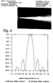
- Figure 4 illustrates the performance characteristics that would be obtained if a full set of cross-products could be used. The problem involved in doing this will be explained in relation to Figure 8.
- Figure 5 illustrates the performance characteristics that would be obtained in using a first limited number of cross-products. More specifically the missing A-scan lines are: 0-4, 0-5, 0-6, 1-5, 1-6, 2-6, 4-0, 5-0, 6-0, 5-1, 6-1 and 6-2.
- Figure 6 illustrates the performance characteristics that would be obtained using a second limited number of cross-products. More specifically the missing A-scan lines are: 0-4, 0-5, 1-5, 2-6, 4-0, 5-1 and 6-2.
- Figure 7 illustrates the performance improvement that is obtainable by applying the optimisation technique of the present invention.
- the multiplexer arrangement shown in Figure 9 avoids having to switch elements between transmission and reception and uses a minimum number of switches
- This arrangement has a number (in this case four) of signal lines. By closing switch S1 and S2, it is possible to transmit on element 1 via line A and receive on element 2 via line B. With this arrangement most cross-products are possible, with the exception of those that have different elements but the same signal line, such as 1-5, 2-6, 3-7, 4-8, 1-9, 1-13, 2-10, 2-14, 3-11, 3-15, 4-12, 4-16.
- This limited cross-product data set gives a beam profile (see Figures 5 and 6) that is not significantly inferior to that obtained by the full cross-product data-set (see Figure 4), and is superior to the prior art single element or group element synthetic aperture approach.
- BB i is the baseband (complex) signal from the k'th element or element group
- F i is a complex filter coefficient.
- the aperture size is 2m+1, and F is only defined for 2m+1 values.
- This equation is then a series of range dependant one dimensional linear convolutions, often referred to as complex filtering.
- both single element and element group synthetic aperture technique produce N independent A-scans, and process these with suitable coefficients to obtain a set of N processed A-scans.
- the data at a particular range can be represented by an N*N matrix, where N is the number of elements, and Bij represents the data transmitting on element i and receiving on j.
- this matrix only has points (shown by solid dots) in a band about its leading diagonal, and there are also lines of forbidden points (shown by circles) that are not permissible with the multiplexer architecture shown in Figure 9.
- the coefficients to produce a single point D n are represented by a (2m + 1) x (2m + 1) array, Fij.
- Each point D n is calculated by a matrix multiplication of Fij with appropriate points for Bij.
- the next point D n+1 is calculated by moving the matrix F along the leading diagonal, and performing another matrix multiplication.
- the complex filter coefficients F determine the lateral response, D n .
- One form the coefficients F can take is given by the conventional synthetic aperture of the following equation (3) where r i ,r j are the distances from the field point r to the elements i,j respectively and A(r i ) is the sensitivity at point r from element i.
- the resultant data set D n is identical to that produced with the conventional dynamic beamforming method at the transmit focus. The only difference is that the data is acquired sequentially rather than in one acquisition, and the response is shown in Figure 4.
- the cross-products may in certain circumstances be limited further by now acquiring data where the same element is used for transmit and receive, represented by B jk in equation 2. Such data will be the most prone to acoustic ring-down and its exclusion from the dataset used for the reconstruction will enable echoes closer to the transducer to be detected.
- the reconstructed response D n can be improved further if the filter coefficients Fij are obtained not from the standard synthetic aperture algorithm of equation (3), but by an optimisation process which minimises the least square array between the reconstructed data set given by equation (2) shown in Figure 18, and a desired acoustic response D'.
- B a matrix representing the cross-product data
- B ij D' is the desired acoustic response
- A is a vector representing an element weighting function
- I is the identity matrix
- ⁇ is a stabilisation constant
- T is the matrix transpose operation
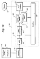
- the hardware implementation of the algorithm of the present invention has to process at a significant rate to produce real-time processing, and this system is illustrated in Figure 13. It consists of the transducer array 10 and multiplexer 20 mounted on the catheter tip, an interface unit 30 to control the multiplexer 20 to address appropriate transducer elements in transmit and receive and to buffer signals, a transceiver unit 95 which performs the processing of the ultrasound data to produce an image, and a display 80.
- the transceiver unit consists of an ADC board 45, which consists of an analogue-digital converter 40 and a data combination circuit 50, a computer based digital beam former 60, which consists of a master DSP board 61 and one or more slave boards 62, and a host computer 80.
- the analogue data in the form of a cross-product baseband quadrature pair B j,k produced by the interface unit 30 is passed to the ADC board 45, where it is converted to a digital signal by the ADC 40.
- the date combination circuit 50 comprises a programmable adder 51 (also known as an ALU (arithmetic logic unit)).
- the circuit 51 adds A+B to make S, so point by point it adds one incoming data set to the previous one stored in the FIFO memory. It is turned off by a signal from the control 53.
- the logic diagram is shown at 54.
- the data array B ij produced by the data combination circuit 50 is passed from the ADC board 45 to the master DSP boards 61 over an industry standard (RACEway TM, Mercury Computer Inc) high speed local data bus.
- RACEway TM Mercury Computer Inc
- the filter matrix F ij will vary with range. In particular for close-in points the best beam profiles are obtained with a smaller aperture (m) than for larger ranges. This is analogous to the use of dynamic aperture in conventional beamforming. It is achieved by modifying F ij to only use values from an aperture less than the matrix size, so many terms will be zero, with a central active sub-matrix.
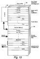
- Figure 15 is the architecture of the particular processing card to perform matrix multiplication of the equation (3).
- a processing card 61 is the Mercury MDV6 (Mercury Computers Inc, Chelmsford, MA), which has up to four reduced-instruction-set (RISC) Intel i860 processors 80, arranged to operate in parallel as an array of vector processors.
- RISC reduced-instruction-set
- Each processor is closely coupled to a fast data cache 90 and also to a RAM external memory 100. Further boards may be added as slave DSP cards 62 to provide more processors.
- Each incoming data line Bij contributes eventually to up to 2m+1 processed lines D n , and to make most efficient use of the high-speed cache memory 90 and processor 80, the 2m+1 products P are calculated in preparation for eventual summation as the data arrives prior to all the data being acquired for the output lines that the input data line contributes to and are stored in the cache memory 90.
- the coefficients Fij remain in the cache memory 90 at all times.
- the storage of partial products in this way allows efficient pipe-line processing of the data.
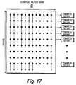
- Each range point has a different set of coefficients Fij, and these are stored as a 3-D matrix (2m+1,R) in the high speed cache memory 90, for multiplication with the data set Bij, which is a vector of length R. This approach avoids the need for coefficients to be continually loaded in and out of high-speed cache memory.
- the system also allows the use of multiple DSP processors 61 and 62 in Figure 13 by sharing the range amongst the processors.
- the processor depicted in Figure 15 handles a fraction of the range, and a number of such processors cover the whole range.
- the data line is calculated from the appropriate sum and stored in external memory on the master board.
- the various ranges are concatenated to produce a full focused A-scan line.
- the coefficients Fij can be calculated from the geometric synthetic aperture formula, and have the form of equation (3).
- processors of Figure 15 sharing the range they could instead share the angular displacement.
- the total amount of processing to be carried out can be divided in a number of ways, including by range or by angular displacement, and then shared out among the plurality of processors.
- the 3-D matrix of coefficients would be the same in each processor in the case where it is the angular displacement which is being shared. In this latter case each processor would produce a segment of the complete focused A-scan lines, and thus perform the same operations and be suited to a parallel architecture which is necessary to obtain the processing rate required.
- each DSP board performs envelope detection and scan conversion from R-format to a rectilinear X-Y format for the A-lines corresponding to a sector of the image, typically one quadrant.
- the DSP boards process their respective sectors in parallel, and on completion, each passes the sub-array to the host computer 90.
- the host computer then assembles the sub-arrays into the full rectilinear X-Y image.
- Such a host computer is a VME Sparc CPU10, (Force Computers Inc, San Jose, CA).
- the DSP board 61 transfers the data to the host computer over a VME bus 96, and the ADC board, DSP boards and host computer are all mounted in a standard VME card cage to form the transceiver 95.
- the signal lines can either be used for transmitting or receiving depending upon the particular transducer element pairing.
- the multiplexer architecture selects less than all of the available cross-products. This not only results in a simpler construction but also avoids the need to switch between transmission and reception.
- the present invention thus overcomes the problem of obtaining high image quality given that the overall physical arrangement is such that it is not possible to have one wire per transducer element. This is achieved by the use of cross-products which are acquired sequentially.
- This acquisition can be achieved by means of a multiplexer although this has the disadvantage of requiring switching between transmission and reception.
- the number of cross-products may be reduced to enable a different multiplexer architecture which eliminates the need for switching between transmission and reception.
- this modified multiplexer architecture it is still possible to obtain good quality images.
- the advantage of this embodiment is that the full cross-product data set can be achieved with less transmit excitations.
- the time saved can be used to give a higher frame rate, or to permit repeat firings with the same settings to allow signal averaging and a higher signal-noise ratio than with sequential acquisition.
- An ultrasonic transducer array 102 is mounted on the distal end of a catheter 101 and is adapted to be inserted into an organ, e.g. artery 103 of a patient in known manner.
- the proximal end of the catheter 104 is connected to a transceiver arrangement shown to the right of the dotted line in Figure 18.
- a multiplexer/demultiplexer arrangement 105 is provided.
- the transducer array 102 is energised by an ultrasonic driving circuit 106 and signals representative of echo pulses received by the transducer array 102 are received by an ultrasonic receiving circuit 107.
- the analogue signals received by the circuit 107 are then converted into digital signals by an analogue-to-digital converter 108 and then passed via a fast-in-fast-out store 109 to a computer/processor 110 which is under stored program control by means of software 111.
- Images representative of the interior of the artery 103 can be displayed on high resolution graphics terminal 112 or printed out by a printer 113.
- Figure 18 is merely to illustrate the kind of intravascular ultrasonic imaging system to which the present invention may be applied.
- Figure 19 shows in more detail the structure of the software 111 of Figure 18. It consists of a processing pipeline 117, which processes the ultrasound data to give an ultrasound image, a B-mode display process 118, which manages the display of that data, and controls contrast and brightness, and communicates with the display window server 119, which incorporates industry standard display routines such as X-windows. Both the processing pipeline and the B-mode display process are managed by the acquisition control 120, which synchronises the processes and is controlled from the WIMP based human interface 121. The human interface also manages other processes such as image manipulation, 122 which is not described in this specification, and it communicates with the database system 123, which manages data handling and file management, including data stored on the storage device 124.
- a processing pipeline 117 which processes the ultrasound data to give an ultrasound image
- a B-mode display process 118 which manages the display of that data, and controls contrast and brightness
- the display window server 119 which incorporates industry standard display routines such as X-windows.
- the pipeline 117 is shown in more detail in Figure 20 together with a sequence control 114.
- the pipeline allows sharing of processors in a multi-process or architecture, and thus can accommodate parallel processing.
- Figure 20 shows the preferred embodiment of this pipeline in which the ultrasound data is focused to give a number of radial A-scans, and then converted to an X-Y display.
- the computer system used to process the real-time B-mode images referred to above has sufficient electronic memory 114 to store this partially processed data frame by frame. This data can then be transferred to an appropriate non-volatile magnetic or opto-magnetic storage media 115 as digital computer compatible files.
- the sequence control process can transfer this data to storage while new data is being acquired, thus limiting the requirements on the buffer size. In this implementation one buffer is being filled with new data, whilst a second buffer is being transferred to storage, and the two buffers alternate their function.
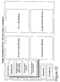
- Figure 22 illustrates how the screen based controls are positioned on the display 113, adjacent to the displayed image.
- Figure 23 is an enlarged more detailed view of the B-mode sequence control panel shown in Figure 22, demonstrating how the screen layout can be designed to present the user with a control panel that is familiar to users of conventional tape VCRs.
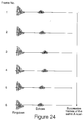
- the ultrasound echo signal, or A-scan arising in a system as shown in Figure 18, and previously described, contains a component that is due to decaying vibration of the transducer following its initial excitation. This is the so-called ringdown. This vibration can persist for 1-2 micro seconds after the initial transmit pulse and can obscure the presence of echoes within 1-2 micro seconds of the transducer. This is illustrated diagrammatically in Figure 24 which shows six successive frames of the same A-scan.
- the reference scans require a field in which there are no echoes, typically in a large vessel such as the aorta, and this can be difficult to obtain.
- the ringdown r(t) can drift with time, so the reference scan needs re-acquiring at periodic intervals, which is inconvenient.
- the solution of the present invention is based on the realisation that whilst the ultrasound echoes will vary significantly from scan to scan the ringdown will only vary slowly.
- the echo will depend on the position and orientation of tissue structure relative to the transducer, and will thus change from scan to scan with movement of the tissue, due to the pulsatible motion of arteries.
- This motion has frequency components related to the pulse rate, typically in the range 1-10Hz.
- the ringdown on the other hand is intrinsic to the transducer element, and independent of the position of neighbouring tissue, and will change due to resonant properties, caused predominantly by small temperature drifts. These changes occur over time-scales of several minutes, and thus are of a significantly different time-scale to the time-scale of echo variation, which latter variation is illustrated in Figure 2.
- the reference scan can be updated by taking a relatively long term running average which can be expressed in the following mathematical terms. and this running average can be subtracted from the current A-scan to remove the ringdown.
- P i (t) A i (t) - ⁇ ⁇ A i (t) + (1- ⁇ )R i-1 (t) ⁇
- the processing of the ultrasound pulses can be considered as a pipeline of four main stages as shown in Figure 25.
- the first stage 214 is signal conditioning, such as d.c. correction, normalisation and digital filtering.
- the second stage 215 is combining channels to perform synthetic aperture focusing.
- the third stage 216 is envelope detection, to extract tissue reflectivity from the ultrasound radio-frequency carrier.
- the fourth stage 217 is scan conversion, to convert the radial information to a form suitable for display on a conventional rectilinear or rastor display device 218, including interpolation between rays as appropriate.
- Figure 26 discloses how the recursive algorithms of Equation 9 can be implemented as a recursive filter, which can be inserted into the pipeline of Figure 25.
- the filter consists of three adder units 220, 224, 226, a memory 221, and a multiplier unit 222. There is one filter for each data point in a frame of data. This filter can be inserted at any stage in the processing pipeline of Figure 25, the most efficient implementations are when the data is at the minimum size, which is before scan conversion, either just after focusing or after demodulation, at points A & B in Figure 25.
- the filter can be implemented in digital hardware using known circuit components. In the preferred implementation it is implemented by the central Processing Unit of the workstation 112 of Figure 18 under stored program control. This has the advantage that the parameter ⁇ , which determines how the filter separates variations of different timescales, can be changed readily. In one implementation the parameter ⁇ can be set automatically, by evaluating the frequency components of motion.
- Equation 9 First a spectral analysis of the temporal frequency components is obtained (Equation 9).
- the parameter ⁇ is then set to discriminate between the low frequency components associated with ringdown, and the high frequency components associated with motion, using a suitable algorithm.
- the preferred algorithm is to search for the frequency F1 at which the power spectrum falls below a certain threshold, and the frequency F2 at which it rises above that threshold.
- the discriminating frequency F ⁇ is set at the arithmetic mean of F1 and F2.
- the ability to be able to interrupt the updating of the reference scan is valuable in the use of preventing erroneous data being fed into the reference scan, for example, when the transducer is being moved into position, and spends long periods against a vessel wall. In these circumstances the vessel wall signal will be only slowly varying, and will be added to the references scan. Interrupting the updating prevents this artifact occurring during positioning of the transducer.
- the updating of the reference scan normally starts from zero, and so a significant number of frames are required for the contents of the reference scan to approach the ringdown only signal.
- an echo free signal is obtained in a suitable large vessel and fed into the long-term memory to act as a initialisation condition, and then updating is continued by the method described.
Landscapes
- Engineering & Computer Science (AREA)
- Physics & Mathematics (AREA)
- Radar, Positioning & Navigation (AREA)
- Remote Sensing (AREA)
- Acoustics & Sound (AREA)
- Computer Networks & Wireless Communication (AREA)
- General Physics & Mathematics (AREA)
- Multimedia (AREA)
- Ultra Sonic Daignosis Equipment (AREA)
- Investigating Or Analyzing Materials By The Use Of Ultrasonic Waves (AREA)
Applications Claiming Priority (6)
| Application Number | Priority Date | Filing Date | Title |
|---|---|---|---|
| GB9418630 | 1994-09-15 | ||
| GB9418630A GB2293240B (en) | 1994-09-15 | 1994-09-15 | Ultrasonic visualisation method and apparatus |
| GB9419778 | 1994-09-30 | ||
| GB9419778A GB2293651B (en) | 1994-09-30 | 1994-09-30 | Medical untrasound imaging |
| GB9426191 | 1994-12-23 | ||
| GB9426191A GB2296565B (en) | 1994-12-23 | 1994-12-23 | Ultrasound imaging |
Publications (3)
| Publication Number | Publication Date |
|---|---|
| EP0702247A2 true EP0702247A2 (de) | 1996-03-20 |
| EP0702247A3 EP0702247A3 (de) | 1998-02-04 |
| EP0702247B1 EP0702247B1 (de) | 2004-11-24 |
Family
ID=27267374
Family Applications (1)
| Application Number | Title | Priority Date | Filing Date |
|---|---|---|---|
| EP95306207A Expired - Lifetime EP0702247B1 (de) | 1994-09-15 | 1995-09-06 | Verfahren und Gerät zur Sichtbarmachung von Ultraschall |
Country Status (3)
| Country | Link |
|---|---|
| EP (1) | EP0702247B1 (de) |
| AT (1) | ATE283496T1 (de) |
| DE (1) | DE69533785D1 (de) |
Cited By (6)
| Publication number | Priority date | Publication date | Assignee | Title |
|---|---|---|---|---|
| EP0829735A2 (de) * | 1996-09-12 | 1998-03-18 | Atlantis Diagnostics International, L.L.C. | Ultraschall-Abbildungssystem für Diagnostik mit Personalcomputer-Architektur |
| WO2000019904A1 (en) * | 1998-10-02 | 2000-04-13 | Boston Scientific Limited | Adaptive cancellation of ring-down artifact in ivus imaging |
| EP1030600A4 (de) * | 1998-09-15 | 2001-01-24 | Endosonics Corp | Verfahren und vorrichtung zur unterdrückung von abklingartefakten |
| US10527592B2 (en) | 2015-09-16 | 2020-01-07 | Samsung Medison Co., Ltd. | Ultrasonic probe, ultrasonic imaging apparatus including the same, and method for controlling the ultrasonic imaging apparatus |
| WO2024105270A1 (fr) * | 2022-11-17 | 2024-05-23 | Resolve Stroke | Procede et systeme d'acquisition et de traitement ultrasonore |
| CN118845087A (zh) * | 2024-02-01 | 2024-10-29 | 青蓝集创医疗设备(成都)有限公司 | 一种超声内镜及其构成的超声成像系统和成像方法 |
Families Citing this family (2)
| Publication number | Priority date | Publication date | Assignee | Title |
|---|---|---|---|---|
| US9345573B2 (en) | 2012-05-30 | 2016-05-24 | Neovasc Tiara Inc. | Methods and apparatus for loading a prosthesis onto a delivery system |
| US10600403B2 (en) * | 2016-05-10 | 2020-03-24 | Invensense, Inc. | Transmit operation of an ultrasonic sensor |
Family Cites Families (6)
| Publication number | Priority date | Publication date | Assignee | Title |
|---|---|---|---|---|
| US4180790A (en) * | 1977-12-27 | 1979-12-25 | General Electric Company | Dynamic array aperture and focus control for ultrasonic imaging systems |
| EP0017383A1 (de) * | 1979-03-20 | 1980-10-15 | THE GENERAL ELECTRIC COMPANY, p.l.c. | Mit Ultraschall arbeitendes Bildgerät |
| US4839652A (en) * | 1987-06-01 | 1989-06-13 | General Electric Company | Method and apparatus for high speed digital phased array coherent imaging system |
| GB2208138B (en) * | 1987-06-19 | 1991-08-07 | Circulation Res Ltd | Tubular probe |
| US4973111A (en) * | 1988-09-14 | 1990-11-27 | Case Western Reserve University | Parametric image reconstruction using a high-resolution, high signal-to-noise technique |
| US5329930A (en) * | 1993-10-12 | 1994-07-19 | General Electric Company | Phased array sector scanner with multiplexed acoustic transducer elements |
-
1995
- 1995-09-06 EP EP95306207A patent/EP0702247B1/de not_active Expired - Lifetime
- 1995-09-06 AT AT95306207T patent/ATE283496T1/de not_active IP Right Cessation
- 1995-09-06 DE DE69533785T patent/DE69533785D1/de not_active Expired - Lifetime
Cited By (10)
| Publication number | Priority date | Publication date | Assignee | Title |
|---|---|---|---|---|
| EP0829735A2 (de) * | 1996-09-12 | 1998-03-18 | Atlantis Diagnostics International, L.L.C. | Ultraschall-Abbildungssystem für Diagnostik mit Personalcomputer-Architektur |
| EP1030600A4 (de) * | 1998-09-15 | 2001-01-24 | Endosonics Corp | Verfahren und vorrichtung zur unterdrückung von abklingartefakten |
| WO2000019904A1 (en) * | 1998-10-02 | 2000-04-13 | Boston Scientific Limited | Adaptive cancellation of ring-down artifact in ivus imaging |
| US6102862A (en) * | 1998-10-02 | 2000-08-15 | Scimed Life Systems, Inc. | Adaptive cancellation of ring-down artifact in IVUS imaging |
| US6254543B1 (en) | 1998-10-02 | 2001-07-03 | Scimed Life Systems, Inc. | Adaptive cancellation of ring-down artifact in IVUS imaging |
| US6589181B2 (en) | 1998-10-02 | 2003-07-08 | Scimed Life Systems, Inc. | Adaptive cancellation of ring-down artifact in imaging |
| US10527592B2 (en) | 2015-09-16 | 2020-01-07 | Samsung Medison Co., Ltd. | Ultrasonic probe, ultrasonic imaging apparatus including the same, and method for controlling the ultrasonic imaging apparatus |
| WO2024105270A1 (fr) * | 2022-11-17 | 2024-05-23 | Resolve Stroke | Procede et systeme d'acquisition et de traitement ultrasonore |
| FR3142262A1 (fr) * | 2022-11-17 | 2024-05-24 | Resolve Stroke | Procédé et systeme d’acquisition et de traitement ultrasonore |
| CN118845087A (zh) * | 2024-02-01 | 2024-10-29 | 青蓝集创医疗设备(成都)有限公司 | 一种超声内镜及其构成的超声成像系统和成像方法 |
Also Published As
| Publication number | Publication date |
|---|---|
| EP0702247A3 (de) | 1998-02-04 |
| EP0702247B1 (de) | 2004-11-24 |
| ATE283496T1 (de) | 2004-12-15 |
| DE69533785D1 (de) | 2004-12-30 |
Similar Documents
| Publication | Publication Date | Title |
|---|---|---|
| US5590659A (en) | Ultrasonic visualization method and apparatus | |
| US5579770A (en) | Multiple transmit zone splicing | |
| US5655536A (en) | Diagnostic ultrasound imaging using two-dimensional transducer array probe | |
| US6102863A (en) | Ultrasonic diagnostic imaging system with thin cable ultrasonic probes | |
| US5257629A (en) | Methods and apparatus for the examination and treatment of internal organs | |
| JP4039643B2 (ja) | 超音波ビーム形成装置 | |
| JP4172841B2 (ja) | 超音波イメージング・システム、超音波イメージング・システムを動作させる方法及びマルチプレクサ・マザーボード | |
| US5690114A (en) | Portable ultrasound imaging system | |
| US4127034A (en) | Digital rectilinear ultrasonic imaging system | |
| US5964709A (en) | Portable ultrasound imaging system | |
| US5957846A (en) | Portable ultrasound imaging system | |
| US5839442A (en) | Portable ultrasound imaging system | |
| US7500952B1 (en) | Portable ultrasound imaging system | |
| US4159462A (en) | Ultrasonic multi-sector scanner | |
| EP0032513B1 (de) | Ultraschall-diagnoseausrüstung | |
| JP4428477B2 (ja) | ビームフォーミング用時間遅延及びアポダイゼーション値の敏速な分散型計算のための方法及び装置 | |
| JP5443326B2 (ja) | 携帯式超音波撮像システム及びプログラム | |
| JPH11508461A (ja) | 携帯式超音波撮像システム | |
| US5027821A (en) | Ultrasonic imaging apparatus | |
| US4434661A (en) | Ultrasonic diagnostic system | |
| JP2009006168A (ja) | 超音波診断装置 | |
| JPH10293171A (ja) | 超音波ビーム形成装置 | |
| JPH0352034B2 (de) | ||
| EP0702247B1 (de) | Verfahren und Gerät zur Sichtbarmachung von Ultraschall | |
| US6254542B1 (en) | Ultrasonic visualization method and apparatus |
Legal Events
| Date | Code | Title | Description |
|---|---|---|---|
| PUAI | Public reference made under article 153(3) epc to a published international application that has entered the european phase |
Free format text: ORIGINAL CODE: 0009012 |
|
| AK | Designated contracting states |
Kind code of ref document: A2 Designated state(s): AT BE CH DE ES FR GB IT LI NL |
|
| 17P | Request for examination filed |
Effective date: 19960905 |
|
| PUAL | Search report despatched |
Free format text: ORIGINAL CODE: 0009013 |
|
| AK | Designated contracting states |
Kind code of ref document: A3 Designated state(s): AT BE CH DE ES FR GB IT LI NL |
|
| 17Q | First examination report despatched |
Effective date: 20000218 |
|
| GRAP | Despatch of communication of intention to grant a patent |
Free format text: ORIGINAL CODE: EPIDOSNIGR1 |
|
| GRAS | Grant fee paid |
Free format text: ORIGINAL CODE: EPIDOSNIGR3 |
|
| GRAA | (expected) grant |
Free format text: ORIGINAL CODE: 0009210 |
|
| AK | Designated contracting states |
Kind code of ref document: B1 Designated state(s): AT BE CH DE ES FR GB IT LI NL |
|
| PG25 | Lapsed in a contracting state [announced via postgrant information from national office to epo] |
Ref country code: NL Free format text: LAPSE BECAUSE OF FAILURE TO SUBMIT A TRANSLATION OF THE DESCRIPTION OR TO PAY THE FEE WITHIN THE PRESCRIBED TIME-LIMIT Effective date: 20041124 Ref country code: LI Free format text: LAPSE BECAUSE OF FAILURE TO SUBMIT A TRANSLATION OF THE DESCRIPTION OR TO PAY THE FEE WITHIN THE PRESCRIBED TIME-LIMIT Effective date: 20041124 Ref country code: IT Free format text: LAPSE BECAUSE OF FAILURE TO SUBMIT A TRANSLATION OF THE DESCRIPTION OR TO PAY THE FEE WITHIN THE PRESCRIBED TIME-LIMIT;WARNING: LAPSES OF ITALIAN PATENTS WITH EFFECTIVE DATE BEFORE 2007 MAY HAVE OCCURRED AT ANY TIME BEFORE 2007. THE CORRECT EFFECTIVE DATE MAY BE DIFFERENT FROM THE ONE RECORDED. Effective date: 20041124 Ref country code: FR Free format text: LAPSE BECAUSE OF NON-PAYMENT OF DUE FEES Effective date: 20041124 Ref country code: CH Free format text: LAPSE BECAUSE OF FAILURE TO SUBMIT A TRANSLATION OF THE DESCRIPTION OR TO PAY THE FEE WITHIN THE PRESCRIBED TIME-LIMIT Effective date: 20041124 Ref country code: BE Free format text: LAPSE BECAUSE OF FAILURE TO SUBMIT A TRANSLATION OF THE DESCRIPTION OR TO PAY THE FEE WITHIN THE PRESCRIBED TIME-LIMIT Effective date: 20041124 Ref country code: AT Free format text: LAPSE BECAUSE OF FAILURE TO SUBMIT A TRANSLATION OF THE DESCRIPTION OR TO PAY THE FEE WITHIN THE PRESCRIBED TIME-LIMIT Effective date: 20041124 |
|
| REG | Reference to a national code |
Ref country code: GB Ref legal event code: FG4D |
|
| REG | Reference to a national code |
Ref country code: CH Ref legal event code: EP |
|
| REF | Corresponds to: |
Ref document number: 69533785 Country of ref document: DE Date of ref document: 20041230 Kind code of ref document: P |
|
| PG25 | Lapsed in a contracting state [announced via postgrant information from national office to epo] |
Ref country code: DE Free format text: LAPSE BECAUSE OF FAILURE TO SUBMIT A TRANSLATION OF THE DESCRIPTION OR TO PAY THE FEE WITHIN THE PRESCRIBED TIME-LIMIT Effective date: 20050225 |
|
| PG25 | Lapsed in a contracting state [announced via postgrant information from national office to epo] |
Ref country code: ES Free format text: LAPSE BECAUSE OF FAILURE TO SUBMIT A TRANSLATION OF THE DESCRIPTION OR TO PAY THE FEE WITHIN THE PRESCRIBED TIME-LIMIT Effective date: 20050306 |
|
| NLV1 | Nl: lapsed or annulled due to failure to fulfill the requirements of art. 29p and 29m of the patents act | ||
| REG | Reference to a national code |
Ref country code: CH Ref legal event code: PL |
|
| PG25 | Lapsed in a contracting state [announced via postgrant information from national office to epo] |
Ref country code: GB Free format text: LAPSE BECAUSE OF NON-PAYMENT OF DUE FEES Effective date: 20050906 |
|
| PLBE | No opposition filed within time limit |
Free format text: ORIGINAL CODE: 0009261 |
|
| STAA | Information on the status of an ep patent application or granted ep patent |
Free format text: STATUS: NO OPPOSITION FILED WITHIN TIME LIMIT |
|
| 26N | No opposition filed |
Effective date: 20050825 |
|
| EN | Fr: translation not filed | ||
| GBPC | Gb: european patent ceased through non-payment of renewal fee |
Effective date: 20050906 |