EP0702248A2 - Détecteur de métal pour al reconnaissance de corps étrangers métalliques - Google Patents
Détecteur de métal pour al reconnaissance de corps étrangers métalliques Download PDFInfo
- Publication number
- EP0702248A2 EP0702248A2 EP95114094A EP95114094A EP0702248A2 EP 0702248 A2 EP0702248 A2 EP 0702248A2 EP 95114094 A EP95114094 A EP 95114094A EP 95114094 A EP95114094 A EP 95114094A EP 0702248 A2 EP0702248 A2 EP 0702248A2
- Authority
- EP
- European Patent Office
- Prior art keywords
- coil
- processing unit
- metal
- difference
- scanning
- Prior art date
- Legal status (The legal status is an assumption and is not a legal conclusion. Google has not performed a legal analysis and makes no representation as to the accuracy of the status listed.)
- Granted
Links
Images


Classifications
-
- G—PHYSICS
- G01—MEASURING; TESTING
- G01V—GEOPHYSICS; GRAVITATIONAL MEASUREMENTS; DETECTING MASSES OR OBJECTS; TAGS
- G01V3/00—Electric or magnetic prospecting or detecting; Measuring magnetic field characteristics of the earth, e.g. declination, deviation
- G01V3/08—Electric or magnetic prospecting or detecting; Measuring magnetic field characteristics of the earth, e.g. declination, deviation operating with magnetic or electric fields produced or modified by objects or geological structures or by detecting devices
-
- A—HUMAN NECESSITIES
- A01—AGRICULTURE; FORESTRY; ANIMAL HUSBANDRY; HUNTING; TRAPPING; FISHING
- A01F—PROCESSING OF HARVESTED PRODUCE; HAY OR STRAW PRESSES; DEVICES FOR STORING AGRICULTURAL OR HORTICULTURAL PRODUCE
- A01F29/00—Cutting apparatus specially adapted for cutting hay, straw or the like
- A01F29/09—Details
- A01F29/16—Safety devices, e.g. emergency brake arrangements
Definitions
- the invention relates to a metal detector for detecting metallic foreign bodies in the flow material, which is conveyed in particular by rotating machine elements of a harvesting machine.
- the metal detector contains magnets for generating a magnetic field which at least partially penetrates into the material flow area and crosses the flow direction, and a scanning coil arrangement for generating electrical signals if the magnetic field is changed by the presence of metal parts in the flow material.
- a signal processing unit evaluates the coil signals and possibly forms a trigger signal which, in particular, brings the rotating machine parts to a standstill.
- a metal detection sensor with only one wire coil is very susceptible to magnetic stray fields, such as those emanating from overhead power lines. For this reason, the first successful metal detector sensors were designed with two coils. The coils were wired so that the voltages of a uniform field cancel each other out. However, the use of coils connected in opposite directions causes another problem. Metal that crosses the sensor on a line bisecting the two coils induces an equal voltage in both coils. These matching voltages cancel each other out and leave no signal that could activate the metal detector. A metal detector system avoids this problem by using four coils and two sets of amplifiers. This solution is expensive and requires matched amplifiers to avoid making the system more sensitive in one surveillance area than in other areas.
- EP-A-0 546 509 describes a metal detection system with three coils. All three coils are connected in series. This system appears to be more sensitive in the middle area than in its end areas. However, it is desirable to have a metal detector with a substantially uniform sensitivity.
- the object on which the invention is based is seen in specifying a multi-coil metal detector of the type mentioned at the outset, which informs the operator which coil is being crossed by a metal piece which triggers. Furthermore, the metal detector is said to be substantially uniform Show sensitivity.
- the metal detector according to the invention preferably has three magnet coil units which are lined up next to one another.
- Each magnet-coil unit has an essentially rectangular coil body, which carries a separate coil and on opposite end sides each carries one of two bar magnets spaced apart from one another.
- the three coils are electrically connected to one another in the manner of a three-phase star connection.
- Each of the voltages generated by the three coils is received by a microprocessor-assisted signal processing unit.
- the signal processing unit generates three differential voltages V (x-y), V (y-z) and V (z-x), which correspond to the differences between two of the three individual coil voltages.
- the signal processing unit generates a sum signal which corresponds to the sum of the absolute values of all differential voltages.
- the signal processing unit determines which side of the coil arrangement is crossed by a piece of metal by comparing the difference signals, which corresponds to the difference between the voltages of the coils lying at the opposite ends of the coil arrangement, to a threshold value.
- the signal processing unit also determines the position of the metal piece more precisely by comparing the individual difference signals with one another.
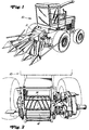
- FIG. 1 and 2 show a forage harvester 10 with a feed area 11 which contains feed rollers 12 and 14 which rotate in order to convey crop to a chopper drum (not shown) and a shear bar (not shown).
- the feed roller 12 is rotatable about a fixed shaft 18 is mounted. The crop travels via the feed roller 12 in the direction indicated by the arrow A, which is perpendicular to the axis of the shaft 18.
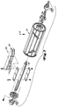
- a metal detector unit 20 contains a housing 22 made of aluminum or a non-magnetizable material, which can be fastened on the shaft 18 within the feed roller 12. Such an arrangement is available as an option for commercially available forage harvesters.
- the structure 24, which is received by the housing 22, preferably contains three identical, substantially rectangular coil formers 26, 27 and 28, the narrow end faces or ends of which face each other and the long sides of which are parallel to the axis of rotation of the Feed roller 12 and lie across the direction of the material flow.
- Separate conductors are wound around each bobbin 26, 27 and 28, forming three pick-up or scanning coils X, Y and Z, the coil axes of which are essentially parallel to one another.
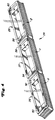
- the coils X, Y and Z have separate, interconnected common connections 30, 32 and 34 and separate output connections 36, 38 and 40.
- Each conductor has 1000 turns between its common connection and its output connection, all of which are wound clockwise in the same direction as shown in FIG.
- Each coil body carries two cuboid bar magnets.
- a pair of permanent magnets 50 and 52 are attached at opposite ends.
- a pair of magnets 54 and 56 are secured within and at opposite ends of the bobbin 27.
- a pair of magnets 58 and 60 are secured within and at opposite ends of the bobbin 28.
- the structure 28 is fastened in the housing 22, preferably cast with epoxy resin.
- the north poles N of all magnets 50-60 point in the same direction, so that their magnetic field lines, not shown, lie parallel to the coil axes and, as shown in FIG. 4, point essentially upwards and as shown in FIG. 5 upwards from the plane of the paper and the outer surface of the feed roller 12 and the Penetrate the material flow path.
- This arrangement of the magnets concentrates the magnetic field at the opposite ends of each coil and reduces it in the center of the coil, forming a substantially uniform field between the ends of adjacent coils.
- the magnetic field of magnet 54 is partially added to the magnetic field of coil 52.
- magnets 56 and 58 If magnets of the same size or strength are used in all six positions shown, the combined magnetic fields in the middle are larger than the magnetic fields at both ends of the coil assembly. To correct this and create a more uniform field, magnet 50 on the outer end of coil X and magnet 60 on the outer end of coil Z are preferably 50% larger or stronger than magnets 52-58.
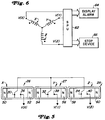
- the coils X, Y and Z are connected to one another in the manner of a three-phase star connection, i. H. one end of each of the coils X, Y and Z opens at a common center point and the other ends of the coils X, Y and Z are available for signal processing.
- the coils X, Y and Z generate voltage signals V (x), V (y) and V (z) at their output connections 36, 38 and 40 in dependence on metal parts which cross the magnetic fields of the magnets 50-60, and in particular ferromagnetic properties exhibit.
- These voltage signals are fed to a signal processing unit (SPU) 62, which controls a display and / or alarm unit 64 and a conventional switch-off device 66, which can be triggered in order to stop the feed rollers 12 and 14.
- SPU signal processing unit
- the signal processing unit 62 contains three differential amplifiers 70 with amplification factors of approximately 83. These make the difference signals V (XY), which represents a difference between V (x) and V (y), V (YZ), which is a difference between V (y) and V (z), and V (ZX), which is a difference between V (z) and V (x).
- the output signals of the differential amplifiers 70 are each through a 1 Hz high-pass filter 72, a 30 Hz low-pass filter 74 with an amplification factor of approximately 3, and a 35 Hz Low pass filter 76 processed with a gain of approximately 6.65.
- the output signals of the low pass filter 76 are received by a multiplexer (MPX) 78.
- a common analog-to-digital converter (A / D) 80 connects the multiplexer 78 to a common microprocessor (MP) 82.
- MP microprocessor
- the microprocessor 82 executes an algorithm 200, as can be seen in the flow chart of FIGS. 8a and 8b.
- the conversion of flow diagram 200 into a programming language, through which the algorithm can be entered into a digital computer or microprocessor, is not a problem for a programmer.
- step 202 the differential voltages V (X-Y), V (Y-Z) and V (Z-X) of the output signals of the signal processing unit 62 are read.
- step 206 a voltage sum Vs is calculated as the sum of the absolute values of V (X-Y), V (Y-Z) and V (Z-X).
- Step 208 returns the algorithm to step 204 if Vs is not greater than an adjustable, programmable threshold of, for example, 0.7 volts. If Vs is greater than the threshold value, the shutdown device 66 is triggered by step 210.
- Absolute values of the difference signals are thus added up and the resulting sum value is compared with a predeterminable limit value in order to determine whether a piece of metal appears anywhere along the coil arrangement 24. If this is the case, the switch-off device is activated in order to interrupt the rotary movement of the feed rollers 12 and 14.
- step 212 V (ZX) is compared to 0 volts. If (ZX) is not greater than 0 volts, it means that metal has appeared somewhere in the left half of the coil assembly 24. Step 214 then generates and stores an appropriate signal and the algorithm proceeds to step 216. If V (ZX) is greater than 0 volts, it means that metal has appeared somewhere in the right half of the coil assembly 24. Step 222 then generates and stores an appropriate signal and the algorithm proceeds to step 224.
- Step 216 compares V (X-Y) with V (Y-Z). If V (X-Y) is greater than V (Y-Z), it means that metal has been detected somewhere in the far left area of coil assembly 24.
- Step 218 then generates and stores a suitable signal and the algorithm proceeds to step 230, which causes a corresponding display on the display 64. The algorithm is then caused to wait for a reset signal in step 232.
- step 216 determines whether metal has been detected somewhere in the left center area of the coil assembly 24.
- Step 220 then generates and stores a suitable signal and the algorithm proceeds to step 230, which causes a corresponding display on the display 64. The algorithm is then caused to wait for a reset signal in step 232.
- Step 224 compares V (ZX) with V (YZ). If V (ZX) is greater than V (YZ), it means that metal has been detected somewhere in the far right area of coil assembly 24.
- Step 226 then generates and stores a suitable signal and the algorithm proceeds to step 230, which causes a corresponding display on the display 64. The algorithm is then caused to wait for a reset signal in step 232.
- step 224 determines whether metal has been detected somewhere in the right central area of the coil assembly 24.
- Step 228 then generates and stores a suitable signal and the algorithm proceeds to step 230, which causes a corresponding display on the display 64. The algorithm is then caused to wait for a reset signal in step 232.
- the algorithm 200 thus analyzes the signals of the coils X, Y and Z and determines the presence or absence of metal and, if metal is present, the algorithm 200 determines the approximate position of the metal relative to the coil arrangement 24.
Landscapes
- Life Sciences & Earth Sciences (AREA)
- Remote Sensing (AREA)
- Physics & Mathematics (AREA)
- Engineering & Computer Science (AREA)
- Environmental & Geological Engineering (AREA)
- Electromagnetism (AREA)
- Environmental Sciences (AREA)
- Geology (AREA)
- General Life Sciences & Earth Sciences (AREA)
- General Physics & Mathematics (AREA)
- Geophysics (AREA)
- Geophysics And Detection Of Objects (AREA)
- Safety Devices And Accessories For Harvesting Machines (AREA)
- Investigating Or Analyzing Materials By The Use Of Magnetic Means (AREA)
- Measurement Of Length, Angles, Or The Like Using Electric Or Magnetic Means (AREA)
Applications Claiming Priority (2)
| Application Number | Priority Date | Filing Date | Title |
|---|---|---|---|
| US08/311,161 US5504428A (en) | 1994-09-16 | 1994-09-16 | Magnetic metal detector mounted in a feed roll of a harvisting machine |
| US311161 | 1994-09-16 |
Publications (3)
| Publication Number | Publication Date |
|---|---|
| EP0702248A2 true EP0702248A2 (fr) | 1996-03-20 |
| EP0702248A3 EP0702248A3 (fr) | 1997-10-01 |
| EP0702248B1 EP0702248B1 (fr) | 2001-12-05 |
Family
ID=23205679
Family Applications (1)
| Application Number | Title | Priority Date | Filing Date |
|---|---|---|---|
| EP95114094A Expired - Lifetime EP0702248B1 (fr) | 1994-09-16 | 1995-09-08 | Détecteur de métal pour la reconnaissance de corps étrangers métalliques |
Country Status (5)
| Country | Link |
|---|---|
| US (1) | US5504428A (fr) |
| EP (1) | EP0702248B1 (fr) |
| JP (1) | JP3625911B2 (fr) |
| CA (1) | CA2156446C (fr) |
| DE (1) | DE59509900D1 (fr) |
Cited By (10)
| Publication number | Priority date | Publication date | Assignee | Title |
|---|---|---|---|---|
| FR2748892A1 (fr) * | 1996-05-22 | 1997-11-28 | Weiss Burkhard | Detecteur de metaux pour reperer la presence d'un metal dans un flux de produit recolte |
| DE19742060A1 (de) * | 1997-09-24 | 1999-03-25 | Claas Selbstfahr Erntemasch | Fremdkörperrückführvorrichtung an Erntemaschinen o. dgl. |
| EP1688031A1 (fr) | 2005-02-07 | 2006-08-09 | CLAAS Selbstfahrende Erntemaschinen GmbH | Dispositif de détection de métal |
| DE102008054488A1 (de) | 2008-12-10 | 2010-06-17 | Deere & Company, Moline | Einrichtung zum Nachweis eines in eine Erntemaschine eingedrungenen Fremdkörpers |
| DE102009000351A1 (de) | 2009-01-21 | 2010-07-29 | Deere & Company, Moline | Schwingungsaufnehmereinheit |
| WO2011134765A1 (fr) | 2010-04-29 | 2011-11-03 | Deere & Comapny | Moissonneuse présentant un dispositif de détection de la présence d'un corps étranger entré dedans |
| EP2514299A1 (fr) | 2011-04-21 | 2012-10-24 | Deere & Company | Installation de contrôle d'un corps étranger ayant pénétré dans une moissonneuse |
| DE102012201906A1 (de) | 2012-02-09 | 2013-08-14 | Deere & Company | Einzugszusammenbau für einen Feldhäcksler |
| DE102013200183B3 (de) * | 2013-01-09 | 2014-04-30 | Deere & Company | Einzugswalze für einen Feldhäcksler |
| DE102012223768A1 (de) | 2012-12-19 | 2014-06-26 | Deere & Company | Fremdkörpernachweiseinrichtung für eine landwirtschaftliche Erntemaschine |
Families Citing this family (27)
| Publication number | Priority date | Publication date | Assignee | Title |
|---|---|---|---|---|
| US5797250A (en) * | 1996-09-27 | 1998-08-25 | Deere & Company | Forage harvester feed roll assembly designed for minimizing false tripping of a metal detector system |
| US6150810A (en) * | 1997-03-24 | 2000-11-21 | Bechtel Bwxt Idaho, Llc | Method for detecting the presence of a ferromagnetic object using maximum and minimum magnetic field data |
| US6084413A (en) * | 1998-04-29 | 2000-07-04 | Mohamed; Moustafa Abdel Kader | Method and apparatus for detecting rock movement |
| DE19843608C1 (de) * | 1998-09-23 | 2000-03-16 | Claas Selbstfahr Erntemasch | Metallortungsvorrichtung in einem Erntegutförderer |
| US7154266B2 (en) * | 2003-01-17 | 2006-12-26 | Quantum Magnetics, Inc. | Screening method and apparatus |
| US6956369B2 (en) * | 2003-01-17 | 2005-10-18 | Mednovus, Inc. | Screening method and apparatus |
| US7315166B2 (en) | 2003-01-17 | 2008-01-01 | Mednovus, Inc. | Magnetic resonance imaging screening method and apparatus |
| US7239134B2 (en) | 2003-01-17 | 2007-07-03 | Mednovus, Inc. | Screening method and apparatus |
| US20040155651A1 (en) * | 2003-02-12 | 2004-08-12 | Britton Andrew Michael | Flux control system for metal detectors |
| DE102004035928A1 (de) * | 2004-07-23 | 2006-03-16 | Claas Selbstfahrende Erntemaschinen Gmbh | Schutzvorrichtung für landwirtschaftliche Arbeitsmaschinen |
| US20060022670A1 (en) * | 2004-07-31 | 2006-02-02 | Mednovus, Inc. | Magnetic resonance screening portal with combination sensing |
| US7239223B2 (en) * | 2004-10-18 | 2007-07-03 | Mednovus, Inc. | Enhancement magnetizer for magnetic resonance imaging screening |
| US20060139025A1 (en) * | 2004-12-24 | 2006-06-29 | Mednovus, Inc. | Saturation-resistant magnetoresistive sensor for ferromagnetic screening |
| US20060145691A1 (en) * | 2004-12-30 | 2006-07-06 | Mednovus, Inc. | Ferromagnetic detection pillar and variable aperture portal |
| US7295107B2 (en) * | 2004-12-30 | 2007-11-13 | Mednovus, Inc. | Ferromagnetic detection pillar |
| US7408461B2 (en) * | 2005-01-11 | 2008-08-05 | Controlled Capture Systems, Llc | Metal detection system and method |
| GB2430036A (en) * | 2005-09-09 | 2007-03-14 | Cnh Belgium Nv | Metal detector arrangement |
| US20070057786A1 (en) * | 2005-09-13 | 2007-03-15 | Mednovus, Inc. | Ferromagnetic threat warning system |
| GB2438578A (en) * | 2006-05-30 | 2007-12-05 | Cnh Belgium Nv | Metal object detection system for harvester |
| US20080055080A1 (en) * | 2006-07-21 | 2008-03-06 | Andrew Michael Britton | Oscillator coil geometry for radio frequency metal detectors |
| US20080281187A1 (en) * | 2006-10-18 | 2008-11-13 | Mednovus, Inc. | Ferromagnetic threat detection method apparatus |
| DE102011117258A1 (de) | 2011-10-27 | 2013-05-02 | Alois Pöttinger Maschinenfabrik Gmbh | Landwirtschaftliche Arbeitsmaschine |
| JP6325327B2 (ja) * | 2013-04-23 | 2018-05-16 | 国立大学法人豊橋技術科学大学 | 磁性金属異物を検出するための装置 |
| JP7132011B2 (ja) * | 2018-07-23 | 2022-09-06 | 株式会社Nippo | 地中レーダ装置及び建設機械 |
| US12063892B2 (en) | 2019-08-15 | 2024-08-20 | Kuhn North America, Inc. | Systems, apparatus, and related methods for use with mergers |
| WO2025099469A1 (fr) | 2023-11-06 | 2025-05-15 | Claas Selbstfahrende Erntemaschinen Gmbh | Machine agricole |
| DE102024108699A1 (de) * | 2024-03-27 | 2025-10-02 | Claas Selbstfahrende Erntemaschinen Gmbh | Landwirtschaftliche Erntemaschine |
Citations (4)
| Publication number | Priority date | Publication date | Assignee | Title |
|---|---|---|---|---|
| US3757501A (en) | 1971-10-29 | 1973-09-11 | Sperry Rand Corp | Static magnetic field metal detector |
| US3889249A (en) | 1971-10-29 | 1975-06-10 | Sperry Rand Corp | Static magnetic field metal detector |
| US3972156A (en) | 1975-02-24 | 1976-08-03 | Sperry Rand Corporation | Speed-independent static magnetic field metal detector |
| EP0546509A2 (fr) | 1991-12-11 | 1993-06-16 | CLAAS SAULGAU GmbH | Dispositif auprès des machines de récolte pour reconnaître des corps étrangers dans la récolte |
Family Cites Families (11)
| Publication number | Priority date | Publication date | Assignee | Title |
|---|---|---|---|---|
| DE546509C (de) * | 1932-03-12 | Fried Krupp Akt Ges | Vorrichtung zum Einstellen der Gasdurchtrittsoeffnungen von Tauchglocken | |
| US2550736A (en) * | 1949-07-15 | 1951-05-01 | Rca Corp | Metal detection apparatus |
| US3964042A (en) * | 1973-06-25 | 1976-06-15 | Sperry Rand Corporation | Static magnetic field metal detector |
| US4344074A (en) * | 1981-04-02 | 1982-08-10 | Sperry Corporation | Magnetic field producing apparatus |
| US4433528A (en) * | 1982-08-30 | 1984-02-28 | Sperry Corporation | Metal detector apparatus |
| CS239075B1 (en) * | 1984-04-10 | 1985-12-16 | Karel Stastny | Metallic admixtures indication device in material |
| DD255432A3 (de) * | 1985-12-24 | 1988-04-06 | Fortschritt Veb K | Vorrichtung zum schutz vor metallischen fremdkoerpern |
| US4785243A (en) * | 1987-01-29 | 1988-11-15 | Ltv Steel Company | Electronically scanned eddy current flaw inspection |
| DE3703449C2 (de) * | 1987-02-05 | 1998-07-23 | Truetzschler Gmbh & Co Kg | Vorrichtung zum Ermitteln von Fremdkörpern, wie Metallteilen, Drähten o. dgl. innerhalb von bzw. zwischen Textilfaserflocken |
| US4788813A (en) * | 1988-01-13 | 1988-12-06 | Ford New Holland, Inc. | Metal detection in the vicinity of ferrous boundaries |
| DE4017780A1 (de) * | 1990-06-01 | 1991-12-05 | Sensoplan Messtechnik Gmbh | Vorrichtung zum feststellen von relativ zu einer metallempfindlichen sensoranordnung bewegten metallteilen |
-
1994
- 1994-09-16 US US08/311,161 patent/US5504428A/en not_active Expired - Lifetime
-
1995
- 1995-08-18 CA CA002156446A patent/CA2156446C/fr not_active Expired - Fee Related
- 1995-09-08 DE DE59509900T patent/DE59509900D1/de not_active Expired - Lifetime
- 1995-09-08 EP EP95114094A patent/EP0702248B1/fr not_active Expired - Lifetime
- 1995-09-12 JP JP23382195A patent/JP3625911B2/ja not_active Expired - Fee Related
Patent Citations (4)
| Publication number | Priority date | Publication date | Assignee | Title |
|---|---|---|---|---|
| US3757501A (en) | 1971-10-29 | 1973-09-11 | Sperry Rand Corp | Static magnetic field metal detector |
| US3889249A (en) | 1971-10-29 | 1975-06-10 | Sperry Rand Corp | Static magnetic field metal detector |
| US3972156A (en) | 1975-02-24 | 1976-08-03 | Sperry Rand Corporation | Speed-independent static magnetic field metal detector |
| EP0546509A2 (fr) | 1991-12-11 | 1993-06-16 | CLAAS SAULGAU GmbH | Dispositif auprès des machines de récolte pour reconnaître des corps étrangers dans la récolte |
Cited By (20)
| Publication number | Priority date | Publication date | Assignee | Title |
|---|---|---|---|---|
| US5901534A (en) * | 1996-05-22 | 1999-05-11 | Claas Kgaa | Metal detector for detecting metal in harvested product flow |
| FR2748892A1 (fr) * | 1996-05-22 | 1997-11-28 | Weiss Burkhard | Detecteur de metaux pour reperer la presence d'un metal dans un flux de produit recolte |
| DE19742060A1 (de) * | 1997-09-24 | 1999-03-25 | Claas Selbstfahr Erntemasch | Fremdkörperrückführvorrichtung an Erntemaschinen o. dgl. |
| US6105347A (en) * | 1997-09-24 | 2000-08-22 | Class Selbstfahrende Erntemaschinen Gmbh | Device and method for locating and removing foreign bodies in agricultural machinery |
| DE19742060B4 (de) * | 1997-09-24 | 2005-02-03 | Claas Selbstfahrende Erntemaschinen Gmbh | Fremdkörperrückführvorrichtung an Erntemaschinen o. dgl. |
| EP1688031A1 (fr) | 2005-02-07 | 2006-08-09 | CLAAS Selbstfahrende Erntemaschinen GmbH | Dispositif de détection de métal |
| US7489130B2 (en) | 2005-02-07 | 2009-02-10 | Claas Selbstfahrende Erntemaschinen Gmbh | Metal detection device |
| BE1019497A5 (fr) * | 2008-12-10 | 2012-08-07 | Deere & Co | Dispositif de mise en evidence d'un corps etranger ayant penetre dans une machine de recolte. |
| DE102008054488A1 (de) | 2008-12-10 | 2010-06-17 | Deere & Company, Moline | Einrichtung zum Nachweis eines in eine Erntemaschine eingedrungenen Fremdkörpers |
| DE102008054488B4 (de) * | 2008-12-10 | 2020-10-22 | Deere & Company | Einrichtung zum Nachweis eines in eine Erntemaschine eingedrungenen Fremdkörpers |
| DE102009000351A1 (de) | 2009-01-21 | 2010-07-29 | Deere & Company, Moline | Schwingungsaufnehmereinheit |
| DE102009000351B4 (de) * | 2009-01-21 | 2011-05-19 | Deere & Company, Moline | Schwingungsaufnehmereinheit |
| WO2011134765A1 (fr) | 2010-04-29 | 2011-11-03 | Deere & Comapny | Moissonneuse présentant un dispositif de détection de la présence d'un corps étranger entré dedans |
| DE102010028343A1 (de) | 2010-04-29 | 2011-12-08 | Deere & Company | Erntemaschine mit einer Einrichtung zum Nachweis eines eingedrungenen Fremdkörpers |
| EP2514299A1 (fr) | 2011-04-21 | 2012-10-24 | Deere & Company | Installation de contrôle d'un corps étranger ayant pénétré dans une moissonneuse |
| DE102011007843A1 (de) | 2011-04-21 | 2012-10-25 | Deere & Company | Einrichtung zum Nachweis eines in eine Erntemaschine eingedrungenen Fremdkörpers |
| DE102012201906A1 (de) | 2012-02-09 | 2013-08-14 | Deere & Company | Einzugszusammenbau für einen Feldhäcksler |
| DE102012223768A1 (de) | 2012-12-19 | 2014-06-26 | Deere & Company | Fremdkörpernachweiseinrichtung für eine landwirtschaftliche Erntemaschine |
| DE102012223768B4 (de) * | 2012-12-19 | 2014-07-03 | Deere & Company | Fremdkörpernachweiseinrichtung für eine landwirtschaftliche Erntemaschine |
| DE102013200183B3 (de) * | 2013-01-09 | 2014-04-30 | Deere & Company | Einzugswalze für einen Feldhäcksler |
Also Published As
| Publication number | Publication date |
|---|---|
| DE59509900D1 (de) | 2002-01-17 |
| US5504428A (en) | 1996-04-02 |
| EP0702248B1 (fr) | 2001-12-05 |
| EP0702248A3 (fr) | 1997-10-01 |
| CA2156446A1 (fr) | 1996-03-17 |
| JPH08101166A (ja) | 1996-04-16 |
| CA2156446C (fr) | 1999-04-27 |
| JP3625911B2 (ja) | 2005-03-02 |
Similar Documents
| Publication | Publication Date | Title |
|---|---|---|
| EP0702248B1 (fr) | Détecteur de métal pour la reconnaissance de corps étrangers métalliques | |
| DE69009541T2 (de) | Eiserne Objekte detektierende Anordnung. | |
| DE2430147C2 (de) | Erntemaschine | |
| DE102015221756B4 (de) | Magneterkennungsvorrichtung und drehmomentsensor hiermit | |
| DE19629934B4 (de) | Sensorsystem | |
| DE4011766C2 (de) | Spannungsmeßfühler | |
| DE102015221757A1 (de) | Magneterkennungsvorrichtung und drehmomentsensor hiermit | |
| DE112018002958B4 (de) | Drehmomentsensoranordnung für fahrzeugservolenkung | |
| EP0229991B1 (fr) | Dispositif de protection contre des objets métalliques | |
| DE102015122179A1 (de) | Drehmomentsensorvorrichtung und Kraftfahrzeug mit einer solchen Drehmomentsensorvorrichtung | |
| DE4300028A1 (fr) | ||
| DE69019491T2 (de) | Verschiebungssensor vom Induktionstyp mit Unempfindlichkeit gegenüber externen magnetischen Feldern. | |
| DE3211819A1 (de) | Erkennungsgeraet fuer metallische fremdkoerper | |
| EP0529440A1 (fr) | Appareil de mesure de la position d'une tôle métallique au moyen inductif | |
| DE60005581T2 (de) | Magnetische Positions- und Richtungserfassung | |
| EP3417245B1 (fr) | Capteur | |
| EP0484716B1 (fr) | Capteur électromagnétique pour déterminer la vitesse et/ou la direction de rotation d'un rotor | |
| EP4242616B1 (fr) | Dispositif de capteur de couple, ensemble de conducteur de flux et conducteur de flux | |
| EP0546509B1 (fr) | Dispositif auprès des machines de récolte pour reconnaître des corps étrangers dans la récolte | |
| DE2301356A1 (de) | Detektorleitung, insbesondere fuer einbruchsicherungsanlagen | |
| DE69001888T2 (de) | Drehzahlmessaufnehmer mit veraenderlichem magnetischem flusswiderstand. | |
| DE3685859T2 (de) | Vibrationsempfindlicher transduktor. | |
| DE3326477A1 (de) | Anordnung zur bestimmung der drehzahl, der drehrichtung und/oder des drehwinkels eines gegenstandes | |
| DE19620526A1 (de) | Metalldetektor zum Erkennen von Metall im Erntegutfluß | |
| EP0659267B1 (fr) | Dispositif pour la saisie geometrique comportant des elements a effet hall |
Legal Events
| Date | Code | Title | Description |
|---|---|---|---|
| PUAI | Public reference made under article 153(3) epc to a published international application that has entered the european phase |
Free format text: ORIGINAL CODE: 0009012 |
|
| AK | Designated contracting states |
Kind code of ref document: A2 Designated state(s): BE DE FR GB IT NL |
|
| PUAL | Search report despatched |
Free format text: ORIGINAL CODE: 0009013 |
|
| AK | Designated contracting states |
Kind code of ref document: A3 Designated state(s): BE DE FR GB IT NL |
|
| 17P | Request for examination filed |
Effective date: 19970927 |
|
| 17Q | First examination report despatched |
Effective date: 19990630 |
|
| GRAG | Despatch of communication of intention to grant |
Free format text: ORIGINAL CODE: EPIDOS AGRA |
|
| GRAG | Despatch of communication of intention to grant |
Free format text: ORIGINAL CODE: EPIDOS AGRA |
|
| GRAH | Despatch of communication of intention to grant a patent |
Free format text: ORIGINAL CODE: EPIDOS IGRA |
|
| GRAG | Despatch of communication of intention to grant |
Free format text: ORIGINAL CODE: EPIDOS AGRA |
|
| GRAH | Despatch of communication of intention to grant a patent |
Free format text: ORIGINAL CODE: EPIDOS IGRA |
|
| GRAG | Despatch of communication of intention to grant |
Free format text: ORIGINAL CODE: EPIDOS AGRA |
|
| GRAH | Despatch of communication of intention to grant a patent |
Free format text: ORIGINAL CODE: EPIDOS IGRA |
|
| RAP1 | Party data changed (applicant data changed or rights of an application transferred) |
Owner name: DEERE & COMPANY |
|
| GRAH | Despatch of communication of intention to grant a patent |
Free format text: ORIGINAL CODE: EPIDOS IGRA |
|
| GRAA | (expected) grant |
Free format text: ORIGINAL CODE: 0009210 |
|
| AK | Designated contracting states |
Kind code of ref document: B1 Designated state(s): BE DE FR GB IT NL |
|
| REG | Reference to a national code |
Ref country code: GB Ref legal event code: IF02 |
|
| REF | Corresponds to: |
Ref document number: 59509900 Country of ref document: DE Date of ref document: 20020117 |
|
| GBT | Gb: translation of ep patent filed (gb section 77(6)(a)/1977) |
Effective date: 20020130 |
|
| ET | Fr: translation filed | ||
| PLBE | No opposition filed within time limit |
Free format text: ORIGINAL CODE: 0009261 |
|
| STAA | Information on the status of an ep patent application or granted ep patent |
Free format text: STATUS: NO OPPOSITION FILED WITHIN TIME LIMIT |
|
| 26N | No opposition filed | ||
| PGFP | Annual fee paid to national office [announced via postgrant information from national office to epo] |
Ref country code: NL Payment date: 20060924 Year of fee payment: 12 |
|
| PG25 | Lapsed in a contracting state [announced via postgrant information from national office to epo] |
Ref country code: NL Free format text: LAPSE BECAUSE OF NON-PAYMENT OF DUE FEES Effective date: 20080401 |
|
| NLV4 | Nl: lapsed or anulled due to non-payment of the annual fee |
Effective date: 20080401 |
|
| PGFP | Annual fee paid to national office [announced via postgrant information from national office to epo] |
Ref country code: IT Payment date: 20080926 Year of fee payment: 14 Ref country code: FR Payment date: 20080917 Year of fee payment: 14 |
|
| PGFP | Annual fee paid to national office [announced via postgrant information from national office to epo] |
Ref country code: GB Payment date: 20080929 Year of fee payment: 14 |
|
| GBPC | Gb: european patent ceased through non-payment of renewal fee |
Effective date: 20090908 |
|
| REG | Reference to a national code |
Ref country code: FR Ref legal event code: ST Effective date: 20100531 |
|
| PG25 | Lapsed in a contracting state [announced via postgrant information from national office to epo] |
Ref country code: FR Free format text: LAPSE BECAUSE OF NON-PAYMENT OF DUE FEES Effective date: 20090930 |
|
| PG25 | Lapsed in a contracting state [announced via postgrant information from national office to epo] |
Ref country code: GB Free format text: LAPSE BECAUSE OF NON-PAYMENT OF DUE FEES Effective date: 20090908 |
|
| PG25 | Lapsed in a contracting state [announced via postgrant information from national office to epo] |
Ref country code: IT Free format text: LAPSE BECAUSE OF NON-PAYMENT OF DUE FEES Effective date: 20090908 |
|
| PGFP | Annual fee paid to national office [announced via postgrant information from national office to epo] |
Ref country code: DE Payment date: 20130821 Year of fee payment: 19 |
|
| PGFP | Annual fee paid to national office [announced via postgrant information from national office to epo] |
Ref country code: BE Payment date: 20130927 Year of fee payment: 19 |
|
| REG | Reference to a national code |
Ref country code: DE Ref legal event code: R119 Ref document number: 59509900 Country of ref document: DE |
|
| REG | Reference to a national code |
Ref country code: DE Ref legal event code: R119 Ref document number: 59509900 Country of ref document: DE Effective date: 20150401 |
|
| PG25 | Lapsed in a contracting state [announced via postgrant information from national office to epo] |
Ref country code: BE Free format text: LAPSE BECAUSE OF NON-PAYMENT OF DUE FEES Effective date: 20140930 |
|
| PG25 | Lapsed in a contracting state [announced via postgrant information from national office to epo] |
Ref country code: DE Free format text: LAPSE BECAUSE OF NON-PAYMENT OF DUE FEES Effective date: 20150401 |