EP0702268B1 - Appareil pour le traitement de matériaux photographiques - Google Patents
Appareil pour le traitement de matériaux photographiques Download PDFInfo
- Publication number
- EP0702268B1 EP0702268B1 EP95114286A EP95114286A EP0702268B1 EP 0702268 B1 EP0702268 B1 EP 0702268B1 EP 95114286 A EP95114286 A EP 95114286A EP 95114286 A EP95114286 A EP 95114286A EP 0702268 B1 EP0702268 B1 EP 0702268B1
- Authority
- EP
- European Patent Office
- Prior art keywords
- photo
- paper
- section
- stock tank
- processing apparatus
- Prior art date
- Legal status (The legal status is an assumption and is not a legal conclusion. Google has not performed a legal analysis and makes no representation as to the accuracy of the status listed.)
- Expired - Lifetime
Links
Images


Classifications
-
- B—PERFORMING OPERATIONS; TRANSPORTING
- B65—CONVEYING; PACKING; STORING; HANDLING THIN OR FILAMENTARY MATERIAL
- B65H—HANDLING THIN OR FILAMENTARY MATERIAL, e.g. SHEETS, WEBS, CABLES
- B65H23/00—Registering, tensioning, smoothing or guiding webs
- B65H23/02—Registering, tensioning, smoothing or guiding webs transversely
- B65H23/032—Controlling transverse register of web
-
- G—PHYSICS
- G03—PHOTOGRAPHY; CINEMATOGRAPHY; ANALOGOUS TECHNIQUES USING WAVES OTHER THAN OPTICAL WAVES; ELECTROGRAPHY; HOLOGRAPHY
- G03D—APPARATUS FOR PROCESSING EXPOSED PHOTOGRAPHIC MATERIALS; ACCESSORIES THEREFOR
- G03D13/00—Processing apparatus or accessories therefor, not covered by groups G11B3/00 - G11B11/00
- G03D13/003—Film feed or extraction in development apparatus
-
- B—PERFORMING OPERATIONS; TRANSPORTING
- B65—CONVEYING; PACKING; STORING; HANDLING THIN OR FILAMENTARY MATERIAL
- B65H—HANDLING THIN OR FILAMENTARY MATERIAL, e.g. SHEETS, WEBS, CABLES
- B65H2511/00—Dimensions; Position; Numbers; Identification; Occurrences
- B65H2511/10—Size; Dimensions
- B65H2511/12—Width
Definitions
- the present invention relates to a photo-processing apparatus, and more particularly to a photo-processing apparatus in which the movement in the transversal direction of the photo-sensitive material (hereinafter called as paper) is restricted in a stock tank section so that the paper will not be twisted.
- a photo-processing apparatus in which the movement in the transversal direction of the photo-sensitive material (hereinafter called as paper) is restricted in a stock tank section so that the paper will not be twisted.
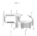
- Fig. 1 shows one example of the configuration of a photo-processing apparatus.
- This photo-processing apparatus consists of a printer section 1 for printing papers and a processor section 2 for performing a process on the printed paper such as developing.
- the printer section 1 is further provided with a loading section 3 for transferring the paper to an exposure stand along a transfer path for the paper, an exposure stand 4 for exposing the paper to light to print it, an advance section 5 for accurately transferring the paper with a certain length, a paper transfer section 6, a stock tank section 7 where a loop is formed to hold the paper so as to adjust the advancing speed of the paper to be sent to the processor section 2, and an exit section 8.
- a processor rack section 9 is provided in the processing tank of the processor section 2 for conducting the coloring and developing, bleaching, and fixing and stabilizing
- a dryer section 10 is provided in the drying tank for drying the paper
- a cutter section 11 is provided near the exit, respectively.
- the strip-shaped paper contained in the paper magazine (not shown) in the form of a roll is pulled out and transferred by a transfer roller, and sent to the processor section 2 through the loading section 3, exposure stand 4, advance section 5 and paper transfer section 6.
- the stock tank section 7 is provided to adjust the advancing speed of the paper to be sent to the processor section 2, and is so designed that it is possible to contain the paper with a certain length in the stock tank section 7 with limited space by a method wherein a small loop is naturally formed in multi-fold laps as shown in Fig. 5.
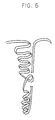
- the number of kinds of paper width that can be processed with a photo-processing apparatus has, however, increased so that the difference between the maximum width and minimum width has increased. If the size of the tank section in the transversal direction is determined in accordance with the maximum width, the minimum size paper will not be restricted in the transversal direction so that the loop is disordered as shown in Fig. 6. In worst cases, there is a problem that the paper cannot be pulled out from the stock tank section because of twist.
- EP-A-0 652 468 describes a mechanism for changing a guide width depending on the width of a photo-sensitive paper in a photo-processing apparatus.
- the mechanism is provided with a pair of guide members, a pair of screw shafts connecting the guide members and a pulse motor rotating the screw shafts through a belt to enlarge or reduce the distance between the guide members. No unthreaded supporting shaft of the guide members is used.
- EP-A-0 519 867 discloses a stock tank for strip material, like exposed photo papers.
- the stock tank is provided with a pair of guide plates and a tank width changing mechanism which changes the distance between the guide plates.
- the changing of the tank width is effected by using screw shafts cooperating with the guide plates. Also this prior art is silent on unthreaded supporting shafts of the stock tank.
- GB-A-2 169 267 refers to an apparatus through which a strip, like a photographic film or print paper, is arranged to be passed.
- the apparatus is provided with guide members for said strip, which are relatively moveable by a separation adjusting mechanism which changes the distance between the guide members.
- the rotating part of the separation adjusting mechanism is a screw shaft having one or more bevel gears. There is no mention of a rotatable supporting shaft of the guide members.
- said apparatus is provided with a sensor for detecting the width of the photo-sensitive material to be passed through the stock tank.
- said apparatus is provided with a sensor for detecting the presence of the photo-sensitive material in the stock tank.
- Fig. 1 illustrates an embodiment of a photo-processing apparatus of the present invention
- Fig. 2 illustrates the stock tank section in the photo-processing apparatus of the present invention
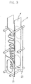
- Fig. 3 illustrates a state of the paper contained in the stock tank section in Fig. 2
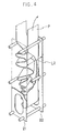
- Fig. 4 illustrates a state of the paper in the case where the width of the stock tank section in Fig. 2 is not changed.
- a configuration of the photo-processing apparatus of the present invention it is possible to use a conventional one.
- the configuration of an embodiment of the photo-processing apparatus of the present invention shown in Fig. 1 is the same as that described above.
- the difference of the present invention from the prior art described above is that a tank width changing mechanism for changing the width of the guide plate in the stock tank section 7 is provided in the stock tank section 7.
- the stock tank section in the present invention comprises a pair of guide plates 21, 22 made of iron group metal plate and the like, a supporting shaft 23 made of stainless steel, brass and the like, and a tank width changing mechanism (not shown) which moves the guide plates 21, 22 in the transversal direction of the paper P.
- the guide plates 21, 22 are thin plates and provided between the paper transfer section 6 and exit section 8 to be paired on the both sides of the paper and to sandwich the transversal direction of the paper.
- the paper fed from the paper transfer section 6 is gathered between the guide plates 21, 22 for a while, and contained and stored till it is sent to the processor section 2 from the exit section 8.
- the guide plates 21, 22 have shaft insertion holes 25, 26 and are supported by a supporting shaft 23.
- the both ends of the supporting shaft 23 are supported by the rear panel of the printer section 1 and stock tank supporting plate of the photo-processing apparatus.
- the tank width changing mechanism it is desirable to use, for example, a mechanism wherein at least one of the supporting shaft 23a, 23b, 23c is divided into threaded right screw and left screw sections so that they rotate in reverse direction each other with an approximate center of the shaft being a border, and to make the supporting shaft insertion hole 25, 26 be a threaded hole correspondingly.
- the unthreaded supporting shaft simply serves as a guide for the movement of the guide plate.
- the supporting shaft is automatically rotated, it is possible to provide a pulley on the supporting shaft to link it to a driving motor by means of a timing belt or to employ a toothed mechanism which is linked to the driving motor.
- a tank width changing mechanism in which a rack is provided to each of the guide plates 21, 22 to face to each other with a pionion being intervened between the tooth of each rack.
- the guide plates 21, 22 symmetrically move when the pinion is rotated. It is possible to provide a sensor on the end section of any rack so as to detect the width of the tank.
- the tank width changing mechanism it is also possible to provide a supporting shaft rotation mechanism on a supporting shaft other than the threaded shaft.
- the supporting shaft rotation mechanism is provided to smoothen the movement of the guide plate 21, 22 by rotating the supporting shaft before the guide plates 21, 22 start to slide so as to change static friction to dynamic friction.
- the center supporting shaft 23b is threaded, and a rotation mechanism is connected to the other supporting shafts 23a, 23c.
- An automatic or manual rotation mechanism is applicable as in the case of the tank width changing mechanism. If the rotation mechanism is connected to a driving motor via a pulley, it is necessary to adjust the rotation mechanism to start before the tank width changing mechanism starts. However, it is possible to terminate the driving at the same time.
- the accuracy of the amount of movement of the guide plates 21, 22 is improved in comparison to the mechanism with the supporting shaft which does not rotate. Namely, in the non-rotatable supporting shaft, sticking dust makes the movement of the guide plate heavier, thereby requiring larger torque or making it difficult to move the guide plate. Furthermore, the guide plate might be caught by the supporting shaft, resulting in irregularity of guiding width or inclined guide plate, thereby causing troubles of zigzagging or clogging the paper transfer.
- rotation of the supporting shaft reduces the friction between the width guide and supporting shaft and smoothens the sliding. In the case of threaded type, particularly, the load on the feed screws is reduced, which reduces driving torque.
- the photo-processing apparatus of the present invention has a tank width changing mechanism in the stock tank section so that the paper to be contained and stored in the stock tank section does not twist and is smoothly pulled out from the exit section by a method wherein the distance between one pair of guide plates restricting the movement of the paper in the transversal direction is adjusted depending on the width of the paper to be passed through the stock tank section.
- a supporting shaft rotation mechanism reduces the friction between the supporting shaft and the guide plates to smoothen the sliding of the guide plates so that the moving amount of the guide plates is accurately controlled, without irregular guiding width and, thus, without trouble in paper transfer.
Landscapes
- Physics & Mathematics (AREA)
- General Physics & Mathematics (AREA)
- Photographic Processing Devices Using Wet Methods (AREA)
- Projection-Type Copiers In General (AREA)
Claims (3)
- Appareil de traitement photographique, comprenant une cuve de réserve (7) destinée à contenir et conserver un matériau photosensible en forme de bande entre deux plaques de guidage (21, 22) qui entourent le matériau photosensible en direction transversale de celui-ci, dans lequel la cuve de réserve a un mécanisme de changement de largeur de cuve qui comporte au moins une tige filetée, grâce auquel la distance entre les deux plaques de guidage peut être changée d'après la largeur de la matière photosensible qui doit passer dans la cuve de réserve, caractérisé en ce que les deux plaques de guidage sont supportées par au moins une tige non filetée de support, et en ce que la cuve de réserve (7) a en outre un mécanisme d'entraínement en rotation de tige de support grâce auquel la tige non filetée de support au moins (23a, 23b, 23c) des plaques de guidage (21, 22), qui se distingue de la tige filetée au moins du mécanisme de changement de largeur de cuve, commence à tourner avant que le mécanisme de changement de largeur de cuve ne commence à fonctionner.
- Appareil de traitement photographique selon la revendication 1, caractérisé en ce qu'il comporte un capteur destiné à détecter la largeur de la matière photosensible (P) qui doit passer dans la cuve de réserve (7).
- Appareil de traitement photographique selon la revendication 1 ou 2, caractérisé en ce qu'il comporte un capteur destiné à détecter la présence de la matière photosensible (P) dans la cuve de réserve (7).
Applications Claiming Priority (6)
| Application Number | Priority Date | Filing Date | Title |
|---|---|---|---|
| JP22314694 | 1994-09-19 | ||
| JP22314694 | 1994-09-19 | ||
| JP223146/94 | 1994-09-19 | ||
| JP16899395 | 1995-07-04 | ||
| JP168993/95 | 1995-07-04 | ||
| JP7168993A JPH08146585A (ja) | 1994-09-19 | 1995-07-04 | 写真処理装置 |
Publications (2)
| Publication Number | Publication Date |
|---|---|
| EP0702268A1 EP0702268A1 (fr) | 1996-03-20 |
| EP0702268B1 true EP0702268B1 (fr) | 2001-12-12 |
Family
ID=26492489
Family Applications (1)
| Application Number | Title | Priority Date | Filing Date |
|---|---|---|---|
| EP95114286A Expired - Lifetime EP0702268B1 (fr) | 1994-09-19 | 1995-09-12 | Appareil pour le traitement de matériaux photographiques |
Country Status (4)
| Country | Link |
|---|---|
| US (1) | US5797058A (fr) |
| EP (1) | EP0702268B1 (fr) |
| JP (1) | JPH08146585A (fr) |
| DE (1) | DE69524510T2 (fr) |
Families Citing this family (3)
| Publication number | Priority date | Publication date | Assignee | Title |
|---|---|---|---|---|
| EP1362814A1 (fr) * | 2002-05-17 | 2003-11-19 | Agfa-Gevaert AG | Dispositif pour stockage intermédiaire de matériau en bande |
| US8757910B2 (en) * | 2009-08-30 | 2014-06-24 | Pitney Bowes Inc. | Printer mounting arrangement for feed guide mechanisms |
| US10336480B2 (en) * | 2015-06-18 | 2019-07-02 | Nexperia B.V. | Air-guided tape-and-reel system and method |
Citations (1)
| Publication number | Priority date | Publication date | Assignee | Title |
|---|---|---|---|---|
| EP0652468A1 (fr) * | 1993-11-10 | 1995-05-10 | Noritsu Koki Co., Ltd. | Méthode de changement de largeur de guide et dispositif utilisé à cet effet |
Family Cites Families (6)
| Publication number | Priority date | Publication date | Assignee | Title |
|---|---|---|---|---|
| US4299458A (en) * | 1980-06-02 | 1981-11-10 | Autologic, Inc. | Self threading phototypesetter transport system |
| JPH0138589Y2 (fr) * | 1984-10-31 | 1989-11-17 | ||
| JP2915619B2 (ja) * | 1991-05-13 | 1999-07-05 | 富士写真フイルム株式会社 | ペーパーマガジン装着装置及び方法 |
| DK0519867T3 (da) * | 1991-06-19 | 1996-11-18 | Gretag Imaging Ag | Lager for båndmateriale |
| JP3171714B2 (ja) * | 1993-01-19 | 2001-06-04 | 富士写真フイルム株式会社 | 画像記録材料の案内保持構造 |
| JP3144219B2 (ja) * | 1993-09-24 | 2001-03-12 | ノーリツ鋼機株式会社 | 写真処理装置 |
-
1995
- 1995-07-04 JP JP7168993A patent/JPH08146585A/ja active Pending
- 1995-09-12 DE DE69524510T patent/DE69524510T2/de not_active Expired - Fee Related
- 1995-09-12 EP EP95114286A patent/EP0702268B1/fr not_active Expired - Lifetime
- 1995-09-14 US US08/528,098 patent/US5797058A/en not_active Expired - Fee Related
Patent Citations (1)
| Publication number | Priority date | Publication date | Assignee | Title |
|---|---|---|---|---|
| EP0652468A1 (fr) * | 1993-11-10 | 1995-05-10 | Noritsu Koki Co., Ltd. | Méthode de changement de largeur de guide et dispositif utilisé à cet effet |
Also Published As
| Publication number | Publication date |
|---|---|
| JPH08146585A (ja) | 1996-06-07 |
| DE69524510D1 (de) | 2002-01-24 |
| US5797058A (en) | 1998-08-18 |
| DE69524510T2 (de) | 2002-08-01 |
| EP0702268A1 (fr) | 1996-03-20 |
Similar Documents
| Publication | Publication Date | Title |
|---|---|---|
| US5967394A (en) | Method and apparatus for pinless feeding of web to a utilization device | |
| FI75543B (fi) | Foerfarande och anordning foer frammatning av en datamaskinsblankettremsa. | |
| US5820007A (en) | Method and apparatus for pinless feeding of web to a utilization device | |
| DE68915921T2 (de) | Elektrofotografisches Aufnahmegerät. | |
| US6196493B1 (en) | Apparatus for conveying photosensitive material | |
| EP0924558B1 (fr) | Appareil pour le traitement de matériau photosensible | |
| EP0702268B1 (fr) | Appareil pour le traitement de matériaux photographiques | |
| EP0622664A2 (fr) | Appareil pour l'alimentation de matériau photosensible | |
| US4903100A (en) | Long strip material handling apparatus | |
| US5532811A (en) | Sheet feed mechanism with control for advancement and retraction of paper | |
| US4955597A (en) | Copying apparatus having a device for holding sheets | |
| DE19953353B4 (de) | Elektrostatische Bilderzeugungsvorrichtung für eine kontinuierliche Papierbahn | |
| US4326791A (en) | Transport system for processor of photosensitive web material | |
| EP0793137B1 (fr) | Méthode de changement de largeur de guide pour matériau photosensible et dispositif utilisé à cet effet | |
| US4900004A (en) | Sheet feeder | |
| US5979820A (en) | Film magazine | |
| DE4420675A1 (de) | Papierwicklungsvorrichtung für photografische Kopiermaschine | |
| EP0854387A1 (fr) | Appareil de traitement d'un film | |
| EP0762191B1 (fr) | Méthode pour dérouler et enrouler du matériau photosensible | |
| DE3902481C2 (de) | Vorrichtung zur Ausbildung thermisch entwickelbarer Aufzeichnungsmaterialien | |
| DE68911177T2 (de) | Verfahren zu Steuerung des Transports eines lichtempfindlichen Trägers. | |
| DE3735670C2 (de) | Fixiervorrichtung | |
| DE60202159T2 (de) | Transportrollmechanismus und fotografische Entwicklungsvorrichtung | |
| JP2877223B2 (ja) | 写真処理装置における感光材料の送り出し方法 | |
| US4980722A (en) | Apparatus for transporting a photosensitive sheet at different speeds in accordance with the operation being performed by the machine |
Legal Events
| Date | Code | Title | Description |
|---|---|---|---|
| PUAI | Public reference made under article 153(3) epc to a published international application that has entered the european phase |
Free format text: ORIGINAL CODE: 0009012 |
|
| AK | Designated contracting states |
Kind code of ref document: A1 Designated state(s): CH DE LI |
|
| 17P | Request for examination filed |
Effective date: 19960618 |
|
| 17Q | First examination report despatched |
Effective date: 19991027 |
|
| GRAG | Despatch of communication of intention to grant |
Free format text: ORIGINAL CODE: EPIDOS AGRA |
|
| GRAG | Despatch of communication of intention to grant |
Free format text: ORIGINAL CODE: EPIDOS AGRA |
|
| GRAH | Despatch of communication of intention to grant a patent |
Free format text: ORIGINAL CODE: EPIDOS IGRA |
|
| GRAH | Despatch of communication of intention to grant a patent |
Free format text: ORIGINAL CODE: EPIDOS IGRA |
|
| GRAA | (expected) grant |
Free format text: ORIGINAL CODE: 0009210 |
|
| RAP1 | Party data changed (applicant data changed or rights of an application transferred) |
Owner name: NORITSU KOKI CO., LTD. |
|
| AK | Designated contracting states |
Kind code of ref document: B1 Designated state(s): CH DE LI |
|
| REG | Reference to a national code |
Ref country code: CH Ref legal event code: NV Representative=s name: RITSCHER & SEIFERT Ref country code: CH Ref legal event code: EP |
|
| REF | Corresponds to: |
Ref document number: 69524510 Country of ref document: DE Date of ref document: 20020124 |
|
| PGFP | Annual fee paid to national office [announced via postgrant information from national office to epo] |
Ref country code: CH Payment date: 20020916 Year of fee payment: 8 |
|
| PLBE | No opposition filed within time limit |
Free format text: ORIGINAL CODE: 0009261 |
|
| STAA | Information on the status of an ep patent application or granted ep patent |
Free format text: STATUS: NO OPPOSITION FILED WITHIN TIME LIMIT |
|
| 26N | No opposition filed | ||
| PG25 | Lapsed in a contracting state [announced via postgrant information from national office to epo] |
Ref country code: LI Free format text: LAPSE BECAUSE OF NON-PAYMENT OF DUE FEES Effective date: 20030930 Ref country code: CH Free format text: LAPSE BECAUSE OF NON-PAYMENT OF DUE FEES Effective date: 20030930 |
|
| REG | Reference to a national code |
Ref country code: CH Ref legal event code: PL |
|
| PGFP | Annual fee paid to national office [announced via postgrant information from national office to epo] |
Ref country code: DE Payment date: 20080926 Year of fee payment: 14 |
|
| PG25 | Lapsed in a contracting state [announced via postgrant information from national office to epo] |
Ref country code: DE Free format text: LAPSE BECAUSE OF NON-PAYMENT OF DUE FEES Effective date: 20100401 |