EP0702393A2 - Appareil de traitement par plasma pour introduire une onde micrométrique issue d'un guide d'onde rectangulaire, à travers une feute allongée dans la chambre à plasma - Google Patents
Appareil de traitement par plasma pour introduire une onde micrométrique issue d'un guide d'onde rectangulaire, à travers une feute allongée dans la chambre à plasma Download PDFInfo
- Publication number
- EP0702393A2 EP0702393A2 EP95306404A EP95306404A EP0702393A2 EP 0702393 A2 EP0702393 A2 EP 0702393A2 EP 95306404 A EP95306404 A EP 95306404A EP 95306404 A EP95306404 A EP 95306404A EP 0702393 A2 EP0702393 A2 EP 0702393A2
- Authority
- EP
- European Patent Office
- Prior art keywords
- microwave
- waveguide
- rectangular waveguide
- plasma chamber
- rectangular
- Prior art date
- Legal status (The legal status is an assumption and is not a legal conclusion. Google has not performed a legal analysis and makes no representation as to the accuracy of the status listed.)
- Ceased
Links
- 238000010168 coupling process Methods 0.000 claims abstract description 21
- 238000005859 coupling reaction Methods 0.000 claims abstract description 21
- 230000008878 coupling Effects 0.000 claims abstract description 20
- 230000005684 electric field Effects 0.000 claims description 114
- 239000003989 dielectric material Substances 0.000 claims description 23
- 238000002834 transmittance Methods 0.000 claims description 15
- 238000003780 insertion Methods 0.000 claims description 13
- 230000037431 insertion Effects 0.000 claims description 13
- 239000000463 material Substances 0.000 claims description 11
- 238000009826 distribution Methods 0.000 description 43
- 238000010276 construction Methods 0.000 description 17
- 230000005855 radiation Effects 0.000 description 12
- 238000003491 array Methods 0.000 description 11
- 238000000034 method Methods 0.000 description 8
- 230000008569 process Effects 0.000 description 7
- 230000002238 attenuated effect Effects 0.000 description 6
- 230000004048 modification Effects 0.000 description 6
- 238000012986 modification Methods 0.000 description 6
- 239000000126 substance Substances 0.000 description 6
- 239000006096 absorbing agent Substances 0.000 description 5
- 239000004020 conductor Substances 0.000 description 5
- RYGMFSIKBFXOCR-UHFFFAOYSA-N Copper Chemical compound [Cu] RYGMFSIKBFXOCR-UHFFFAOYSA-N 0.000 description 4
- 229910052782 aluminium Inorganic materials 0.000 description 4
- XAGFODPZIPBFFR-UHFFFAOYSA-N aluminium Chemical compound [Al] XAGFODPZIPBFFR-UHFFFAOYSA-N 0.000 description 4
- 230000008859 change Effects 0.000 description 4
- 229910052802 copper Inorganic materials 0.000 description 4
- 239000010949 copper Substances 0.000 description 4
- 230000001902 propagating effect Effects 0.000 description 4
- 239000007787 solid Substances 0.000 description 4
- 230000000694 effects Effects 0.000 description 3
- 150000002500 ions Chemical class 0.000 description 3
- 229920003002 synthetic resin Polymers 0.000 description 3
- 239000000057 synthetic resin Substances 0.000 description 3
- XLYOFNOQVPJJNP-UHFFFAOYSA-N water Substances O XLYOFNOQVPJJNP-UHFFFAOYSA-N 0.000 description 3
- VYPSYNLAJGMNEJ-UHFFFAOYSA-N Silicium dioxide Chemical compound O=[Si]=O VYPSYNLAJGMNEJ-UHFFFAOYSA-N 0.000 description 2
- 230000009471 action Effects 0.000 description 2
- 239000000919 ceramic Substances 0.000 description 2
- 230000003247 decreasing effect Effects 0.000 description 2
- 238000005530 etching Methods 0.000 description 2
- 229910052751 metal Inorganic materials 0.000 description 2
- 239000002184 metal Substances 0.000 description 2
- 230000002093 peripheral effect Effects 0.000 description 2
- 238000004804 winding Methods 0.000 description 2
- 239000004698 Polyethylene Substances 0.000 description 1
- 239000004809 Teflon Substances 0.000 description 1
- 229920006362 Teflon® Polymers 0.000 description 1
- PNEYBMLMFCGWSK-UHFFFAOYSA-N aluminium oxide Inorganic materials [O-2].[O-2].[O-2].[Al+3].[Al+3] PNEYBMLMFCGWSK-UHFFFAOYSA-N 0.000 description 1
- 238000004380 ashing Methods 0.000 description 1
- 230000015572 biosynthetic process Effects 0.000 description 1
- 238000004519 manufacturing process Methods 0.000 description 1
- 238000009828 non-uniform distribution Methods 0.000 description 1
- -1 polyethylene Polymers 0.000 description 1
- 229920000573 polyethylene Polymers 0.000 description 1
- 230000000644 propagated effect Effects 0.000 description 1
- 238000007670 refining Methods 0.000 description 1
- 239000004065 semiconductor Substances 0.000 description 1
- 239000010409 thin film Substances 0.000 description 1
Images


Classifications
-
- H—ELECTRICITY
- H01—ELECTRIC ELEMENTS
- H01J—ELECTRIC DISCHARGE TUBES OR DISCHARGE LAMPS
- H01J37/00—Discharge tubes with provision for introducing objects or material to be exposed to the discharge, e.g. for the purpose of examination or processing thereof
- H01J37/32—Gas-filled discharge tubes
- H01J37/32009—Arrangements for generation of plasma specially adapted for examination or treatment of objects, e.g. plasma sources
- H01J37/32192—Microwave generated discharge
- H01J37/32211—Means for coupling power to the plasma
- H01J37/32229—Waveguides
-
- H—ELECTRICITY
- H01—ELECTRIC ELEMENTS
- H01J—ELECTRIC DISCHARGE TUBES OR DISCHARGE LAMPS
- H01J37/00—Discharge tubes with provision for introducing objects or material to be exposed to the discharge, e.g. for the purpose of examination or processing thereof
- H01J37/32—Gas-filled discharge tubes
- H01J37/32009—Arrangements for generation of plasma specially adapted for examination or treatment of objects, e.g. plasma sources
- H01J37/32192—Microwave generated discharge
- H01J37/32211—Means for coupling power to the plasma
- H01J37/32238—Windows
-
- H—ELECTRICITY
- H01—ELECTRIC ELEMENTS
- H01J—ELECTRIC DISCHARGE TUBES OR DISCHARGE LAMPS
- H01J37/00—Discharge tubes with provision for introducing objects or material to be exposed to the discharge, e.g. for the purpose of examination or processing thereof
- H01J37/32—Gas-filled discharge tubes
- H01J37/32009—Arrangements for generation of plasma specially adapted for examination or treatment of objects, e.g. plasma sources
- H01J37/32192—Microwave generated discharge
- H01J37/32211—Means for coupling power to the plasma
- H01J37/32247—Resonators
- H01J37/32256—Tuning means
-
- H—ELECTRICITY
- H01—ELECTRIC ELEMENTS
- H01J—ELECTRIC DISCHARGE TUBES OR DISCHARGE LAMPS
- H01J37/00—Discharge tubes with provision for introducing objects or material to be exposed to the discharge, e.g. for the purpose of examination or processing thereof
- H01J37/32—Gas-filled discharge tubes
- H01J37/32431—Constructional details of the reactor
- H01J37/3266—Magnetic control means
-
- H—ELECTRICITY
- H01—ELECTRIC ELEMENTS
- H01J—ELECTRIC DISCHARGE TUBES OR DISCHARGE LAMPS
- H01J37/00—Discharge tubes with provision for introducing objects or material to be exposed to the discharge, e.g. for the purpose of examination or processing thereof
- H01J37/32—Gas-filled discharge tubes
- H01J37/32431—Constructional details of the reactor
- H01J37/32733—Means for moving the material to be treated
- H01J37/32752—Means for moving the material to be treated for moving the material across the discharge
- H01J37/32761—Continuous moving
- H01J37/3277—Continuous moving of continuous material
Definitions
- the present invention relates to a plasma processing apparatus, and in particular, to a plasma processing apparatus for radiating a microwave from at least one rectangular waveguide through at least one long slot to a plasma chamber, the above-mentioned plasma processing apparatus being provided for, uniformly and at a high speed, performing a plasma processing, such as thin film formation, surface refining, etching or the like, toward an object to be processed having a large area.
- a plasma processing such as thin film formation, surface refining, etching or the like
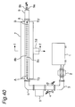
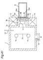
- Fig. 40 is a plan view showing a general construction of a prior art plasma processing apparatus which is disclosed in the Japanese Patent Laid-Open Publication No. 5-335095, and Fig. 41 is a cross-sectional view taken along a line I - I' of Fig. 40.
- this prior art plasma processing apparatus comprises:
- a long projection 7b for communicating with the inside of the plasma chamber 7 is provided on a side wall 7a of the plasma chamber 7 formed on the rectangular waveguide 8 side of the plasma chamber 7, and the projection 7b is opposed to one E-plane 8a of the rectangular waveguide 8.
- an electromagnet 10 used as first magnetic-field generating means is provided on the outer periphery of the projection 7b, and a narrow rectangular window 7c is formed on the rectangular waveguide 8 side of the projection 7b so as to extend along the waveguide-axis direction of the rectangular waveguide 8.
- the window 7c is sealed under vacuum by a microwave transmitting window 11 made of a silica glass plate, and then, the plasma chamber 7 is sealed under vacuum.
- an exhaust port 7d is formed and connected to a vacuum pump (not shown), and a gas introducing pipe 12 for introducing a process gas into the plasma chamber 7 is attached to one wall of the plasma chamber 7 so as to penetrate or pass through the wall of the plasma chamber 7 in airtight fashion.
- long slots or longitudinal slots 8b and 8c are formed in the E-plane 8a of the rectangular waveguide 8 so as to extend in the waveguide-axis direction of the rectangular waveguide 8.
- Each of these long slots 8b and 8c has a length substantially equal to the longitudinal length of the window 7c of the plasma chamber 7, however, the width of each of the long slots 8b and 8c is set to a value shorter than the width of the window 7c.
- the rectangular waveguide 8 is electrically connected to the plasma chamber 7 with the long slots 8b and 8c so as to oppose to the window 7c of the plasma chamber 7.
- a microwave generated by the microwave power supply 1 is introduced or radiated into the rectangular waveguide 8 through the isolator 2, the corner rectangular waveguide 3, the directional coupler 4, the automatic impedance matching device 5, and the corner rectangular waveguide 6. Then, the microwave is radiated or projected into the plasma chamber 7 from the long slots 8b and 8c through the window 7c.
- a permanent magnet 10c used as a second magnetic-field generating means is disposed at a widthwise center portion of the E-plane 8a along the long slots 8b and 8c. Furthermore, a rectangular-cylindrical-shaped microwave waveguide forming member 16 made of aluminum, copper, stainless, or the like is placed longitudinally around the permanent magnet 10c so as to support the permanent magnet 10c and moreover to form microwave waveguides 8. The microwave waveguide forming member 16 is fixed between the plasma chamber 7 and the rectangular waveguides 16a and 16a' by appropriate means.
- the terminating unit 9 is provided with a microwave absorber for absorbing excess microwave which have not been supplied into the plasma chamber 7 side, wherein water is used as the microwave absorber in this case.
- the excess microwave which has not propagated to the plasma chamber 7 are absorbed by water introduced through an inlet port 9a, and the water heated by the microwave is drained through a drain port 9b.
- the object 13 to be processed is provided and set in the plasma chamber 7, and then, the interior of the plasma chamber 7 is evaporated to a high vacuum. Thereafter, a predetermined process gas is supplied through the gas introducing pipe 12 into the plasma chamber 7 until the plasma chamber interior is pressurized to a predetermined pressure.
- a predetermined process gas is supplied through the gas introducing pipe 12 into the plasma chamber 7 until the plasma chamber interior is pressurized to a predetermined pressure.
- the microwave excites the process gas within the plasma chamber 7 into the plasma, then a strip-shaped plasma is generated along the window 7c of the plasma chamber 7.
- the object 13 to be processed is wound and moved by the roll 15.
- the processing in a larger area can be implemented in continuous fashion onto the object 13.
- the electromagnet 10 which is divergent magnetic field generating means for forming a divergent magnetic field
- the electromagnet 10 which is divergent magnetic field generating means for forming a divergent magnetic field
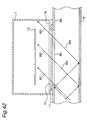
- the microwave radiated from the long slot 8b having a length AB into the plasma chamber 7 propagates in such a fashion as to be skewed toward one side of the plasma chamber 7, as shown by microwaves W1, W2 and W3 in Fig. 42 showing a cross-sectional view taken along a line T3 - T3' of Fig. 40.
- the resulting electric field intensity is non-uniform along the longitudinal direction of the plasma chamber 7, as shown in Fig. 43.
- AB ⁇ provided in the rectangular waveguide 8 have peaks and valleys of standing waves due to reflected waves generated with the long slots 8a and 8b provided, regardless of the fact that the terminating unit 9 is provided comprising the microwave absorber.
- the resulting electric field intensity is of a non-uniform distribution having peaks and valleys as shown in Fig. 43. Accordingly, there is such a disadvantage that the distribution of the plasma generated is non-uniform, such that plasma processing could not-be attained over larger areas of the object 13 to be processed.
- the microwave absorber of the terminating unit 9 is consumed by the microwave absorber of the terminating unit 9, and therefore, this results in power loss. Accordingly, there is such a further disadvantage that the use efficiency of the microwave power is relatively poor and the density of the generated plasma is relatively low.
- a plasma processing apparatus comprising: a plasma chamber having a narrow window formed in a side wall thereof, an object to be processed being provided inside said narrow window; a rectangular waveguide for coupling with said plasma chamber, said rectangular waveguide having a long slot disposed in an E-plane thereof so as to oppose to said narrow window of said plasma chamber and to extend along a waveguide-axis direction of said rectangular waveguide, said rectangular waveguide being provided so that the waveguide-axis direction of said rectangular waveguide is parallel to a longitudinal direction of said narrow window of said plasma chamber; and microwave power supply means for supplying a microwave to said rectangular waveguide, wherein the microwave is radiated from said rectangular waveguide to said plasma chamber through said long slot, said plasma processing apparatus being characterized in further comprising: at least two said long slots disposed in at least one said rectangular waveguide; wherein the longitudinal length of said each long slot is set to 1/2 or more of a free-space wavelength of the microwave; and wherein said long slots are disposed so as
- the above-mentioned plasma processing apparatus may comprise: at least two said rectangular waveguides each having at least one said long slot; and further microwave power supply means for supplying a microwave to another one of said rectangular waveguides in a direction different from the direction of one of said rectangular waveguides adjacent to another one of said rectangular waveguides.
- each of said long slots may be a slot array composed of a plurality of sub-slots disposed by equally dividing said long slot in the waveguide-axis direction of said rectangular waveguide, said plasma processing apparatus further comprising: a terminating unit provided at a terminating end of said rectangular waveguides and having a movable short-circuit plate provided so as to move along the waveguide-axis direction of said rectangular waveguide, wherein said movable short-circuit plate is positioned so that center portions of peaks of a voltage standing wave generated in said rectangular waveguides are coincident with longitudinal center portions of said sub-slots, respectively.
- the above-mentioned plasma processing apparatus may further comprise: one said rectangular waveguide having one long slot, said long slot being a slot array composed of a plurality of sub-slots disposed by equally dividing said long slot in the waveguide-axis direction of said rectangular waveguide; and a terminating unit provided at a terminating end of said rectangular waveguide and having a movable short-circuit plate provided so as to move along the waveguide-axis direction of said rectangular waveguide, wherein said movable short-circuit plate is positioned so that center portions of peaks of a voltage standing wave generated in said rectangular waveguide are coincident with longitudinal center portions of said sub-slots, respectively.
- a plasma processing apparatus comprising: a plasma chamber having a narrow window disposed in a side wall thereof, an object to be processed being provided inside said narrow window; a rectangular waveguide for-coupling with said plasma chamber, said rectangular waveguide having a long slot disposed in an E-plane thereof so as to oppose to said narrow window of said plasma chamber and to extend along a waveguide-axis direction of said rectangular waveguide, said rectangular waveguide.being provided so that the waveguide-axis direction of said rectangular waveguide is parallel to a longitudinal direction of said narrow window of said plasma chamber; and microwave power supply means for supplying a microwave to said rectangular waveguide, wherein the microwave is radiated from the rectangular waveguide to said plasma chamber through said long slot, said plasma processing apparatus being characterized in that: a longitudinal length of said long slot is set to 1/2 or more of a free-space wavelength of the microwave, said plasma processing apparatus further comprising: a microwave waveguide forming member provided between said long slot and said narrow window of said plasma chamber, said
- the length of said dielectric in the longitudinal direction of said long slot may be set to n/2 of a free-space wavelength of the microwave where n is a natural number, and wherein an insertion length of said dielectric into said microwave waveguide is set by adjusting a microwave transmittance coefficient of said dielectric so that an electric field intensity of the microwave along the longitudinal direction of said plasma chamber becomes substantially uniform.
- a plasma processing apparatus comprising: a plasma chamber having a narrow window disposed in a side wall thereof, an object to be processed being provided inside said narrow window; a rectangular waveguide for coupling with said plasma chamber, said rectangular waveguide having a long slot disposed in an E-plane thereof so as to oppose to said narrow window of said plasma chamber and to extend along a waveguide-axis direction of said rectangular waveguide, said rectangular waveguide being provided so that the waveguide-axis direction of said rectangular waveguide is parallel to a longitudinal direction of said narrow window of said plasma chamber; and microwave power supply means for supplying a microwave to said rectangular waveguide, wherein the microwave is radiated from the rectangular waveguide to said plasma chamber through said long slot, said plasma processing apparatus being characterized in that: a longitudinal length of said long slot is set to 1/2 or more of a free-space wavelength of the microwave, said plasma processing apparatus further comprising: a movable short-circuit plate provided at a terminating end of said rectangular waveguide so
- a plasma processing apparatus comprising: a plasma chamber having a narrow window disposed in a side wall thereof, an object to be processed being provided inside said narrow window; a rectangular waveguide for coupling with said plasma chamber, said rectangular waveguide having a long slot disposed in an E-plane thereof so as to oppose to said narrow window of said plasma chamber and to extend along a waveguide-axis direction of said rectangular waveguide, said rectangular waveguide being provided so that the waveguide-axis direction of said rectangular waveguide is parallel to a longitudinal direction of said narrow window of said plasma chamber; and microwave power supply means for supplying a microwave to said rectangular waveguide, wherein the microwave is radiated from the rectangular waveguide to said plasma chamber through.
- said long slot said plasma processing apparatus being characterized in that: a longitudinal length of said long slot is set to 1/2 or more of a free-space wavelength of the microwave, said plasma processing apparatus further comprising: a movable slot plate having an opening having a length shorter than a longitudinal length
- a plasma processing apparatus comprising: a plasma chamber having a narrow window disposed in a side wall thereof, an object to be processed being provided inside said narrow window; a rectangular waveguide for coupling with said plasma chamber, said rectangular waveguide having a long slot disposed in an E-plane thereof so as to oppose to said narrow-window of said plasma chamber and to extend along a waveguide-axis direction of said rectangular waveguide, said rectangular waveguide being provided so that the waveguide-axis direction of said rectangular waveguide is parallel to a longitudinal direction of said narrow window of said plasma chamber; and microwave power supply means for supplying a microwave to said rectangular waveguide, wherein the microwave is radiated from the rectangular waveguide to said plasma chamber through said long slot, said plasma processing apparatus being characterized in that: a longitudinal length of said long slot is set to 1/2 or more of a free-space wavelength of the microwave, said plasma processing apparatus further comprising: magnetic-field generating means for generating a magnetic field in a space between said microwave
- the above-mentioned plasma processing apparatus may further comprise: at least two microwave waveguide forming members provided between each said long slot and said narrow window of said plasma chamber and having a microwave waveguide having a cross section identical to an opening shape of each said long slot; and at least two dielectrics each made of a material that does not absorb any microwave, and said dielectrics being inserted into said microwave waveguides at a position near a terminating end of said rectangular waveguides along the waveguide-axis direction of said rectangular waveguide, said dielectrics reflecting a part of the microwave and transmit another part of the microwave, wherein the length of each said dielectric in the longitudinal direction of each said long slot is set to n/2 of a free-space wavelength of the microwave where n is a natural number, and wherein an insertion length of each said dielectric into each said microwave waveguide is set by adjusting a microwave transmittance coefficient of each said dielectric so that an electric field intensity of the microwave along the longitudinal direction of said plasma chamber becomes substantially uniform.
- the above-mentioned plasma processing apparatus may further comprise: at least two said rectangular waveguides each having at least one said long slot; and further microwave power supply means for supplying a microwave to another one of said rectangular waveguides in a direction different from the direction of one of said rectangular waveguides adjacent to another one of said rectangular waveguides, and wherein said long slots are disposed so as to be parallel to each other such that adjacent said long slots are shifted from each other by (2n-1)/4 of the free-space wavelength of the microwave in the waveguide-axis direction of said rectangular waveguide, where n is a natural number.
- the above-mentioned plasma processing apparatus may further comprise: a microwave waveguide forming member provided between said long slot and said narrow window of said plasma chamber, said microwave waveguide forming member having a microwave waveguide having a cross section identical to an opening shape of said long slot; and a dielectric made of a material that does not absorb any microwave, said dielectric being inserted into said microwave waveguide at a position near a terminating end of said rectangular waveguide along the waveguide-axis direction of said rectangular waveguide, said dielectric reflecting a part of the microwave and transmitting another part of the microwave.
- a length of said dielectric in the longitudinal direction of said long slot may be set to n/2 of a free-space wavelength of the microwave where n is a natural number, and wherein an insertion length of said dielectric into said microwave waveguide is set by adjusting a microwave transmittance coefficient of said dielectric so that an electric field intensity of the microwave along the longitudinal direction of said plasma chamber becomes substantially uniform.
- At least two long slots are provided in at least one rectangular waveguide, and the longitudinal length of each long slot is set to 1/2 or more of the free-space wavelength of the microwaves, wherein the long slots are arranged so as to be shifted from each other by (2n-1)/4 (where n is a natural number) of the free-space wavelength of the microwave in the waveguide-axis direction of the rectangular waveguide.
- the microwave electric field radiated from the long slots to the plasma chamber has peaks and valleys with a cycle corresponding to the free-space wavelength of the microwaves
- the strong portions and weak portions of the electric field of the microwave can be superimposed on each other by shifting the positions of the individual long slots by a phase of (2n-1)/4 of the free-space wavelength of the microwaves.
- the power of the microwave radiated to the plasma chamber can be made uniform along the longitudinal direction of the window of the plasma chamber, so that a uniform plasma density can be obtained over a wider range or area.
- the above-mentioned plasma processing apparatus further comprises at least two said rectangular waveguides each having at least one long slot, and further microwave power supply means for supplying the microwaves to the rectangular waveguides in directions different from each other between adjacent rectangular waveguides. Therefore, regions where the electric field intensity of the microwave radiated from one rectangular waveguide through one long slot is relatively weak receive a relatively strong electric field of the microwave radiated from the further rectangular waveguide through the other long slot, and then the strong portions and the weak portions of the electric field of microwave can be superimposed on each other.
- the power of the microwaves radiated to the plasma chamber can be made uniform along the longitudinal direction of the window of the plasma chamber, so that a uniform plasma density can be obtained over a wider range or area.
- each of the long slots is a slot array composed of a plurality of sub-slots formed by equally dividing the long slot in the waveguide-axis direction.
- the above-mentioned plasma processing apparatus further comprises: a terminating unit provided at a terminating end of the rectangular waveguides and having a movable short-circuit plate provided so as to move along the waveguide-axis direction, the movable short-circuit plate being positioned so that center portions of peaks of a voltage standing wave generated in the rectangular waveguides are coincident with longitudinal center portions of the sub-slots, respectively.
- the peaks of the electric field intensity of the microwave radiated from each sub-slot of the slot array become substantially a constant, so that the magnitude of the strong portions and the weak portions of the electric field intensity of the microwave is reduced over the entire length of the slot array.
- the above-mentioned plasma processing apparatus further comprises: one said rectangular waveguide having one long slot, the long slot being a slot-array composed of a plurality of sub-slots formed by equally dividing the long slot in the waveguide-axis direction; a terminating unit provided at a terminating end of said rectangular waveguide and having a movable short-circuit plate provided so as to move along the waveguide-axis direction, the movable short-circuit plate being positioned so that center portions of peaks of a voltage standing wave generated in the rectangular waveguide are coincident with longitudinal center portions of the sub-slots, respectively.
- the peaks of the microwave electric field intensities of the microwave radiated from each sub-slot of the slot array become substantially a constant, so that the magnitude.of the strong portions and the weak portions of the electric field intensities of the microwaves is reduced over the entire longitudinal length of the slot array.
- the above-mentioned plasma processing apparatus further comprises: a microwave waveguide forming member provided between the long slot and the window of the plasma chamber and having a microwave waveguide having a cross section identical to an opening shape of the long slot; and a dielectric composed of a material that does not absorb the microwaves, and inserted into the microwave waveguide at a position near a terminating end of the rectangular waveguide along the waveguide-axis direction, the dielectric reflecting a part of the microwave and transmitting another part of the microwave.
- the dielectric which reflects a part of the microwave and transmits another part of the microwave and that does not absorb any microwave, at a portion where the electric field intensity of the microwaves is relatively high, the strong portions of the electric field are weakened while the weak portions of the electric field are conversely reinforced by power reflected by the dielectric.
- the power of the microwaves radiated to the plasma chamber can be made more uniform along the longitudinal direction of the window of the plasma chamber, so that a uniform plasma density can be obtained over a wide range.
- the longitudinal length of the dielectric along the longitudinal direction of the long slot is set to n/2 (where n is a natural number) of a free-space wavelength of the microwaves, and an insertion length of the dielectric into the microwave waveguide is set by adjusting the microwave transmittance coefficient of the dielectric so that an electric field intensity of the microwaves along the longitudinal direction of the plasma chamber becomes substantially uniform.
- n is a natural number
- an insertion length of the dielectric into the microwave waveguide is set by adjusting the microwave transmittance coefficient of the dielectric so that an electric field intensity of the microwaves along the longitudinal direction of the plasma chamber becomes substantially uniform.
- a longitudinal length of the long slot is set to 1/2 or more of a free-space wavelength of the microwaves.
- the above-mentioned plasma processing apparatus further comprises: a movable short-circuit plate provided at a terminating end of the rectangular waveguide so as to move along the waveguide-axis direction over a longitudinal length of 1/2 or more of a guide wavelength of the microwaves; and movement driving means for moving the movable short-circuit plate periodically or non-periodically along the waveguide-axis direction.
- the non-uniformity of plasma can be complemented by changing the irradiation of plasma to the object to be processed in time and space.
- a plasma processing with apparently good uniformity can be accomplished.
- a longitudinal length of the long slots is set to 1/2 or more of a free-space wavelength of the microwaves.
- the above-mentioned plasma processing apparatus further comprises: a movable slot plate having an opening in a space between the long slot of the rectangular waveguide, and the narrow window of the plasma chamber, the movable slot plate having a longitudinal length shorter than the length of the long slot in the waveguide-axis direction and a width equal to the width of the long slot, the movable slot plate disposed so as to move along the waveguide-axis direction so that the long slot and the opening are opposed to each other; and movement driving means for moving the movable slot plate periodically or non-periodically over a longitudinal length of 1/2 or more of the free-space wavelength of the microwaves.
- the non-uniformity of plasma can be complemented by varying the irradiation of plasma to the object to be processed in time and space.
- a plasma processing with apparently good uniformity can be accomplished.
- a longitudinal length of the long slot is set to 1/2 or more of a free-space wavelength of the microwaves.
- the above-mentioned plasma processing apparatus further comprises: magnetic-field generating means for generating a magnetic field in a space between the object set in the plasma chamber and the window, and for changing a direction and an intensity of the magnetic field.
- the non-uniformity of plasma can be complemented by varying the irradiation of plasma to the object to be processed in time and space.
- the plasma processing with apparently good uniformity can be accomplished.
- the above-mentioned plasma processing apparatus further comprises: at least two microwave waveguide forming members provided between each long slot and the narrow window of the plasma chamber and having a microwave waveguide having a cross section identical to an opening shape of the each long slot; and at least two dielectrics each composed of a material that does not absorb any microwave, and inserted in said microwave waveguides at a position near a terminating end of the rectangular waveguides along the waveguide-axis direction, the dielectrics reflecting a part of the microwave and transmitting another part of the microwave, wherein the longitudinal length of said each dielectric in the longitudinal direction of said each long slot is set to n/2 (where n is a natural number) of a free-space wavelength of the microwaves, and an insertion length of each dielectric into each microwave waveguide is set by adjusting the microwave transmittance coefficient of said each dielectric so that an electric field intensity of the microwaves along the longitudinal direction of the plasma chamber becomes substantially uniform.
- the dielectric that reflects a part of the microwave and transmits another-part of the microwave and that does not absorb any microwaves, at a portion where the electric field intensity of the microwaves is relatively high, the strong portions of the electric field are weakened while the weak portions of the electric field are conversely reinforced by power reflected by the dielectric.
- the power of the microwaves radiated to the plasma chamber can be made uniform along the longitudinal direction of the window of the plasma chamber, so that a uniform plasma density can be obtained over a wide range.
- the above-mentioned plasma processing apparatus further comprises: at least two said rectangular waveguides each having at least one long slot; and further microwave power supply means for supplying the microwave to the rectangular waveguides in directions different between adjacent rectangular waveguides, wherein the long slots are formed so as to be parallel to each other in such a way that adjacent the long slots are shifted from each other by (2n-1)/4 (where n is a natural number) in the waveguide-axis direction of the rectangular waveguide.
- regions where the electric field intensity of the microwave radiated from one rectangular waveguide through one long slot is relatively weak receive a relatively strong electric field of the microwave radiated from the other rectangular waveguide through the other long slot, and then the strong portions and the weak portions of the electric field of the microwave can be superimposed on each other.
- the power of the microwave radiated to the plasma chamber can be made uniform along the longitudinal direction of the window of the plasma chamber, so that a uniform plasma density can be obtained over a wide range.
- the above-mentioned plasma processing apparatus further comprises: a microwave waveguide forming member provided between the long slot and the window of the plasma chamber and having a microwave waveguide having a cross section identical to an opening shape of the long slot; and a dielectric composed of a material that does not absorb any microwave, and inserted into the microwave waveguide at a position near a terminating end of the rectangular waveguide along the waveguide-axis direction, the dielectric reflecting a part of the microwave and transmitting another part of the microwave.
- the dielectric that reflects a part of the microwave and transmits another part of the microwave and that does not absorb any microwave, at a portion-where the electric field intensity of the microwave is relatively high, the strong portions of the electric field are weakened while the weak portions of the electric field are conversely reinforced by power reflected by the dielectric.
- the power of the microwave radiated to the plasma chamber can be made uniform along the longitudinal direction of the window of the plasma chamber, so that a uniform plasma density can be obtained over a wide range.
- the above-mentioned plasma processing apparatus further comprises: a microwave waveguide forming member provided between the long slot and the window of the plasma chamber and having a microwave waveguide whose cross section is identical to an opening shape of the long slot; and a dielectric composed of a material that does not absorb any microwave, and inserted into the microwave waveguide at.a position near a terminating end of the rectangular waveguide along the waveguide-axis direction, the dielectric reflecting a part of the microwave and transmitting another part of the microwave, wherein the length of the dielectric along the longitudinal direction of the long slot is set to n/2 (where n is a natural number) of a free-space wavelength of the microwave, and an insertion length of the dielectric into the microwave waveguide is set by adjusting the microwave transmittance coefficient of the dielectric so that an electric field intensity of the microwave along the longitudinal direction of the plasma chamber becomes substantially uniform.
- the dielectric that reflects a part of the microwave and transmits another part of the microwave and that does not absorb any microwave, at a portion where the electric field intensity of the microwave is relatively high, the strong portions of the electric field are weakened while the weak portions of the electric field are conversely reinforced by power reflected by the dielectric.
- the power of the microwave radiated to the plasma chamber can be made uniform along the longitudinal direction of the window of the plasma chamber, so that a uniform plasma-density can be obtained over a wider range or area.
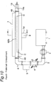
- Fig. 1 is a general construction view of a plasma processing apparatus showing a first preferred embodiment according to the present invention.
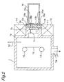
- Fig. 2 is a cross-sectional view taken along a line I - I' of Fig. 1.
- Fig. 1 there are shown the followings:
- the plasma processing apparatus of the first preferred embodiment according to the present invention is characterized in that the long slots 18b and 18c are located so as to be shifted from each other in the waveguide-axis direction by (2n-1)/4 (where n is a natural number) of the free space wavelength ⁇ 0 of the microwave, and so as to be both parallel to the waveguide-axis direction of the rectangular waveguide 18 with an appropriate spacing.
- a long projection 7b for communicating with the inside of the plasma chamber 7 is provided onto a side wall 7a of the plasma chamber 7 on the rectangular waveguide 18 side of the plasma chamber 7, and the projection 7b is formed so as to oppose to one E-plane 18a of the rectangular waveguide 18.
- an electromagnet 10 used as first magnetic-field generating means is provided on the outer periphery of the projection 7b, and a narrow rectangular window 7c is provided on the rectangular waveguide 18 side of the projection 7b so as to extend along the waveguide-axis direction of the rectangular waveguide 18.
- the window 7c is sealed under vacuum by a microwave transmitting window 11 made of a silica glass plate, and then the plasma chamber 7 is sealed under vacuum.
- an exhaust port 7d is provided and connected to a vacuum pump (not shown), and a gas introducing pipe 12 for introducing a process gas into the plasma chamber 7 is attached so as to pass through one wall of the plasma chamber 7 in airtight fashion.
- long slots 18b and 18c are formed in the E-plane 18a of the rectangular waveguide 18 so as to extend in the waveguide-axis direction of the rectangular waveguide 18.
- the long slots 18b and 18c are located so as to be shifted from each other in the waveguide-axis direction thereof by (2n-1)/4 (where n is a natural number) of the free-space wavelength ⁇ 0 of the microwave and, besides, so as to be both parallel to each other with an appropriate spacing.
- a window 7c is formed in the side wall 7a of the plasma chamber 7 on the rectangular waveguide 18 side thereof so as to extend in the waveguide-axis direction of the rectangular waveguide 18, and the longitudinal length of the window 7c is set to a value approximately or substantially equal to a longitudinal length resulting by adding ⁇ 0(2n-1)/4 to the longitudinal length of one long slot 18b or 18c, as described above.
- the rectangular waveguide 18 is electrically connected to the plasma chamber 7 with the long slots 18b, 18c opposed to the window 7c of the plasma chamber 7.
- a permanent magnet 10c used as second magnetic-field generating means is disposed at the widthwise center portion of the E-plane 18a of the rectangular waveguide 18 along the long slots 18b and 18c.
- a rectangular-cylindrical-shaped microwave waveguide forming member 16 made of aluminum, copper, stainless, or the like is placed longitudinally around the. permanent magnet 10c so as to support the permanent magnet 10c and moreover so as to form microwave waveguides 16a and 16a'.
- the microwave waveguide forming member 16 is fixed between the plasma chamber 7a and the rectangular waveguide 18 by appropriate means.
- the terminating unit 19 is provided the movable short-circuit plate 19a instead of a terminating unit consisting of a microwave absorber as shown in Fig. 40 of the prior art. Accordingly, by respectively adjusting the position of the movable short-circuit plate 19a and the automatic impedance matching device 5 to predetermined impedances as required, the microwave to be introduced into the rectangular waveguide 18 can be supplied to the plasma chamber 7 with a higher efficiency.
- a microwave generated by the microwave power supply 1 is introduced to the rectangular waveguide 18 through the isolator 2, the corner rectangular waveguide 3, the directional coupler 4, the automatic impedance matching device 5, and the corner rectangular waveguide 6. Then, the microwave is radiated or projected into the plasma chamber 7 from the long slots 18b and 18c through the microwave waveguides 16a and 16a', the microwave transmitting window 11, and the window 7c.
- the electric field intensity of the microwave radiated from the long slots 18b and 18c has strong portions and weak portions alternately every halves of the free-space wavelength ⁇ 0 of the microwave as shown in Fig. 43
- shifting the long slots 18b and 18c from each other by 1/2 of the free-space wavelength ⁇ 0 of the microwave along the longitudinal direction of the long slots 18b and 18c, that is, in the waveguide-axis direction of the rectangular waveguide 18 causes two microwave electric fields to be combined or synthesized so that the strong and weak portions of the electric field intensity are superimposed on each other.
- the longitudinal length to which the long slots 18b and 18c are shifted from each other is set to a value of (1/4) ⁇ 0 or (3/4) ⁇ 0.
- the longitudinal length of each of the long slots 18b and 18c is set to a longitudinal length n( ⁇ 0/2), where n is preferably a natural number equal to or greater than 1, and further, n is more preferably a natural number equal to or greater than 2.
- n is set to a large number, for example, in excess of 4 to the length of the object 13 to be processed, the attenuation of microwave electric fields becomes larger in the longitudinal direction of the long slots 18b and 18c.
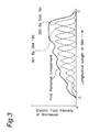
- the distribution of the electric field intensities of the microwaves radiated from slots of a longitudinal length CD given by the long slots 18b and 18c is shown by a solid line of Fig. 3, wherein the magnitudes of the strong portion and the weak portion of the electric field intensities are reduced so that substantially a constant electric field intensity can be obtained. It is noted that broken lines 301 and 302 in Fig. 3 show distributions of the electric field intensities of the microwaves radiated from the long slots 18b and 18c, respectively. Further, in the present preferred embodiment using the terminating unit 19 which can adjust the impedance, the microwave reflected by the terminating unit 19 can be also introduced to the plasma chamber 7.
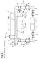
- Fig. 4 is a general construction view of a plasma processing apparatus showing a second preferred embodiment according to the present invention.
- Fig. 5 is a cross-sectional view taken along a line I - I' of Fig. 4. In Fig. 4, there are shown the followings:
- the.microwave power supply 1', the isolator 2', the corner rectangular waveguide 3', the directional coupler 4', the automatic impedance matching device 5', the rectangular waveguide 28', and the terminating unit 19' are connected in series, in a manner similar to that of the microwave power supply 1, the isolator 2, the corner rectangular waveguide 3, the directional coupler 4, the automatic impedance matching device 5, the rectangular waveguide 28, and the terminating unit 19.
- the rectangular waveguides 28 and 28' are respectively arranged so as to be juxtaposed and have long slots 28b and 28b' provided in the E-planes 28a and 28a' of the rectangular waveguides 28 and 28' along the waveguide-axis direction.
- the long slots 28b and 28b' are located so as to be shifted from each other in the waveguide-axis direction of the rectangular waveguides 28 and 28' by 1/4 or 3/4 of a free-space wavelength ⁇ 0 of the microwave, and in parallel to each other with an appropriate spacing.
- the distribution of the electric field intensity of the microwave radiated from the long slot 28b is shown by the pattern of Fig. 43, while the distribution of the electric field intensity of the microwave radiated from the long slot 28b' has a pattern reverse to that shown in Fig. 43. Therefore, by shifting the long slots 28b and 28b' by a longitudinal length of 1/4 or 3/4 of the free-space wavelength ⁇ 0 of the microwave, two electric field intensities of the microwaves are combined or synthesized so that strong portions and weak portions of electric field intensities are superimposed on each other as that in the first preferred embodiment.
- the distribution of the electric field intensities of the microwaves radiated from the long slots 28b and 28b' is shown by a solid line of Fig. 6, so that the distribution of the electric field intensity of the combined microwave becomes more uniform over the entire longitudinal length of the long slots. Thus, the uniformity thereof is further improved. It is noted that broken lines 311 and 312 in Fig. 6 represent the distributions of the electric field intensities of the microwaves radiated from the long slots 28b and 28b', respectively.
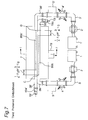
- Fig. 7 is a general construction view of a plasma processing apparatus showing a third preferred embodiment according to the present invention.
- the third preferred embodiment is arranged in a manner similar to that shown in Fig. 5 showing the second preferred embodiment, except that two rectangular waveguides 38 and 38' each provided for coupling with the plasma chamber 7, wherein the rectangular waveguides 38 and 38' have slot arrays 80b and 80b', respectively.
- the components similar to those shown in Figs. 1 and 4 are designated by the same numerals as those shown in Figs. 1 and 4.
- the slot arrays 80b and 80b' are provided on E-planes 38a and 38a' of the rectangular waveguides 38 and 38', respectively, along the waveguide-axis direction of the rectangular waveguides 38 and 38', and each of the slot arrays 80b and 80b' is made up from a plurality of small sub-slots 80s each formed so as to extend in the waveguide-axis direction of the rectangular waveguides 38 and 38', wherein the sub-slots 80s are arrayed in line or aligned in a gathered form.
- each sub-slot 80s is set to 1/2 of the free-space wavelength ⁇ 0 of the microwave, and the sub-slots 80s are arrayed at intervals of 1/2 of the guide wavelength ⁇ g of each microwave propagating within the rectangular waveguides 38 and 38'.
- the slot arrays 80b and 80b' are positioned so as to be parallel to each other with an appropriate spacing and so as to be shifted from each other by 1/4 or 3/4 of the free-space wavelength ⁇ 0 of the microwave along the waveguide-axis direction of the rectangular waveguides 38 and 38'.
- ⁇ g > ⁇ 0.
- the electric field intensities of the microwaves radiated therefrom have strong portions and weak portions alternately every halves of the free-space wavelength ⁇ 0 of the microwave. Therefore, by shifting the slot arrays 80b and 80b' to each other by (1/4) ⁇ 0 or (3/4) ⁇ 0, two electric field intensities of the microwaves are combined or synthesized so that the strong and weak portions of the-electric field intensity of the microwaves are superimposed on each other.
- the distributions of the electric field intensities of the microwaves radiated from the slot arrays 80b and 80b' are shown by broken lines 321 and 322, respectively, in Fig. 9. Accordingly, the distributions of the electric field intensities of the microwaves radiated from slots having a longitudinal length CD of the two slot arrays 80b and 80b' become substantially uniform over the entire longitudinal length of the slot arrays 80b and 80b' as shown by solid lines of Fig. 9.
- a plasma is generated by using the resulting electric field intensity of the combined microwave, the strong portions and the weak portions of the plasma density with respect to the waveguide-axis direction of the rectangular waveguides 38 and 38' are reduced so that a more uniform plasma can be generated.
- Fig. 10 is a general construction view of a plasma processing apparatus showing a fourth preferred embodiment according to the present invention. This preferred embodiment is arranged in a manner similar to that as in Fig. 1 showing the first preferred embodiment, except that one rectangular waveguide 48 is provided with one slot array 80b.
- the components similar to those in Fig. 1 are designated by the same numerals as those shown in Figs. 1.
- the slot array 80b used in the present preferred embodiment is absolutely the same as the slot array 80b shown in Fig. 8.
- the longitudinal length of each sub-slot 80s is set to 1/2 of the free-space wavelength ⁇ 0 of the microwave, and the sub-slots 80s are arranged at intervals of 1/2 of the guide wavelength ⁇ g of the microwave propagating within the rectangular waveguide 48.
- the distribution of the electric field intensity of the microwave radiated from the slot array 80b is such that, as shown by broken lines of Fig. 11, strong portions and weak portions of electric field intensities of the microwaves with respect to the waveguide-axis direction of the rectangular waveguide 48 are reduced over the entire longitudinal length of the slot array 80b.
- a plasma is generated by using the resultant electric field intensity of the combined microwave, for example, with a relatively low gas pressure, the plasma density distribution becomes a state shown by a solid line of Fig. 11.
- a plasma with good uniformity can be generated despite the presence of the strong portions and the weak portions of the electric field intensities of the microwaves.
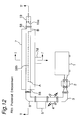
- Fig. 12 is a general construction view showing a fifth preferred embodiment according to the present invention
- Fig. 13 is a partly cross-sectional view taken along a line I - I' of Fig. 12.
- Fig. 12 there are shown the followings:
- the microwave waveguide forming member 26 is composed of a good electrical conductor metal such as copper, aluminum or the like, and electrically connects the plasma chamber 7 with the rectangular waveguide 58.
- the cross section of the microwave waveguide forming member 26 is formed into a narrow rectangular shape, which is identical to that of the long slot 58b.
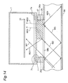
- Fig. 14 is a partly cross-sectional view taken along a line T - T' of Fig. 12.
- the dielectric 27 of, for example, a rectangular parallelopiped shape is inserted, wherein the dielectric 27 is composed of a substance which does not absorb the microwave, for example, which is made of ceramics, synthetic resin or the like.
- the dielectric 27 a substance that does not absorb the microwave, a microwave is partly reflected by the dielectric 27 and the remaining microwave is transmitted by the dielectric to reach the window 7c of the plasma chamber 7.
- the dielectric 27 on the termination side of the rectangular waveguide 58, that is, at a position where the microwave electric field is relatively strong a microwave W2 is reflected by the dielectric 27, then the reflected microwave becomes a microwave W21, while the remaining microwave is transmitted through the dielectric 27 so as to become a microwave W22.
- the microwave W21 acts to intensify the originally weak portions of the electric field intensity of the microwave within the plasma chamber 7, whereas the microwave W22, conversely, has been attenuated so as to have a microwave power less than that of the microwave W2, acting to weaken the originally strong portions of the electric field intensity of the microwave in the plasma chamber 7.
- a microwave W31 reflected by the dielectric 27 is reflected by the movable short-circuit plate 19a, and the reflected microwave is finally. supplied to the plasma chamber 7.
- a microwave W32 which has passed through the dielectric 27 has been further attenuated so as to have a less microwave power in a manner similar to that of the microwave W22, so that the microwave W32 acts to weaken the originally strong portions of the electric field intensity of the microwave.
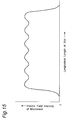
- the distribution of the electric field intensity of the microwave radiated from the long slot 58b is, as shown in Fig. 15, substantially uniform along the longitudinal direction of the plasma chamber 7, so that the uniformity of the distribution of the electric field intensity of the microwave is further improved. Thus, a plasma with a higher density can be generated.
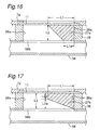
- Dielectrics 27a and 27b shown in Figs. 16 and 17 are modifications in the shape of the dielectric 27, and are designed for attaining more uniformity of the distribution of the electric field intensity of the microwave by gradually reducing the thickness of each of the dielectrics 27a and 27b over a range or area from the strong portions to the weak portions of the electric field intensity of the microwave. That is, in the case of Fig. 16, the cross-sectional shape of the dielectric 27a has a width L1a on the rectangular waveguide 58 side, a width L1 (> L1a) on the plasma chamber 7 side, and a thickness L2. Further, in the case of Fig.
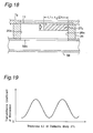
- a dielectric 27c shown in Fig. 18 is predetermined in dimensions, so as to have a width L1 and a thickness L2.
- the electric field intensity of the microwave radiated into the plasma chamber 7, as shown in Fig. 43, has the strong portions and the weak portions alternating with a cycle corresponding to 1/2 of the free-space wavelength ⁇ 0 of the microwave. Accordingly, by setting the longitudinal length L1 of the dielectric 27c along the longitudinal direction of the long slot 58b to n/2 (where n is a natural number) of the free-space wavelength ⁇ 0 of the microwave, a better matching with the space on the plasma chamber 7 side can be obtained. Thus, the supply efficiency of the microwave is enhanced while the disturbance of the electric field intensities of the microwave radiated into the plasma chamber 7 can be minimized.
- Fig. 19 which shows the relationship between the thickness L2 and the microwave transmittance coefficient of the dielectric 27c
- the microwave transmittance coefficient of the dielectric 27c is adjusted by increasing or decreasing the insertion length L2 of the dielectric 27c into the microwave waveguide 26a over a range or area from the strong portion to the weak portion of the electric field intensity of the microwave, then the distribution of the electric field intensity of the microwave along the longitudinal direction of the plasma chamber 7 can be enhanced in uniformity. That is, the insertion length L2 is selectively set so that the transmittance coefficient of the dielectric 27c is reduced at regions where the electric field intensity of the microwave is relatively higher, while the transmittance coefficient of the dielectric 27c is increased at regions where the electric field intensity of the microwave is relatively lower. In other words, the insertion length L2 is set by adjusting the transmittance coefficient of the dielectric 27c so that a uniform field distribution can be attained along the longitudinal direction of the plasma chamber 7.
- a substance having a large dielectric constant ⁇ r may be selected for those dielectrics 27, 27a, 27b and 27c since the characteristic impedance in a dielectric medium depends on the dielectric constant ⁇ r thereof and is 1/( ⁇ r )1/2 times the value in vacuum.
- a dielectric material such as ceramics, alumina or the like may be used.
- a substance having a small dielectric constant ⁇ r may be selected for those dielectrics 27, 27a, 27b and 27c.
- a synthetic resin such as polyethylene or teflon may be used as the dielectrics.
- Fig. 20 is a general construction view showing a sixth preferred embodiment according to the present invention.
- Fig. 21 is a partly cross-sectional view taken along a line T - T' of Fig. 20.
- Fig. 20 there are shown the followings:
- the short-circuit plate driving unit 91 comprises a disc 91a supported by a shaft 110 at the center of the disc 91a and rotated in a rotational direction of arrow 100 by a stepping motor or the like, and a drive bar 91b whose one end is supported by a shaft 111 so that the drive bar 91b can be rotated about a peripheral end portion of the disc 91a away from the center thereof, whereas another end of the drive bar 91b is connected to the center portion of the movable short-circuit plate 19a.
- the movable short-circuit plate 19a can be reciprocatingly moved automatically and yet periodically or non-periodically along the waveguide-axis direction of the rectangular waveguide 58, as indicated by arrow 200.
- the standing wave occurring within the rectangular waveguide 58 also changes depending on the movement of the movable short-circuit plate 19a. Therefore, the standing wave changes as W1, W2, W3, W2, W1, W2, W3, ... when reciprocatingly moving the movable short-circuit plate 19a along the waveguide-axis direction.
- the standing wave W1 is shown by a one-dot chain line
- the.standing wave W2 is shown by a broken line
- the standing wave W3 is shown by a solid line.
- the plasma can be radiated apparently substantially uniformly to the individual sections of the object 13 to be processed.
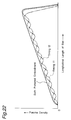
- the plasma density distribution due to the electric field intensity of the microwave radiated from the long slot 58b is, as shown by a solid line of Fig. 22, more uniform along the longitudinal direction of the plasma chamber 7. It is noted that the broken lines shown in Fig. 22 represent plasma density distributions at timings t1 and t2.
- the moving distance of the movable short-circuit plate 19a is preferably to at least approximately 1/2 of the guide wavelength ⁇ g of the rectangular waveguide 58, and so as to move the movable short-circuit plate 19a continuously over the distance thereof. It is preferably to set the moving cycle of the movable short-circuit plate 19a to a period, for example, not more than 1/10 of the processing time of the sheet-shaped object 13 to be processed.
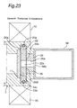
- Fig. 23 showing a seventh preferred embodiment according to the present invention, is a partly cross-sectional view taken along the line I - I' of Fig. 12 showing the fifth preferred embodiment.
- Fig. 24 is a cross-sectional view taken along a line equivalent to the line T - T' of Fig. 12.
- a movable slot plate 22 bearings 23a and 23b, flexible conductors 24a, 24b, 24c and 24d, and a slot plate driving unit 92 for driving the movable slot plate 22.
- the components similar to those shown in Figs. 12 and 13 are designated by the same numerals as those shown in Figs. 12 and 13.
- the movable slot plate 22 is composed of a good electrical conductor metal such as aluminum, copper, stainless or the like, and is provided in a space between the long slot 58b and the microwave transmitting window 11 in such a way that the movable slot plate 22 can be moved along the waveguide-axis direction of the rectangular waveguide 58 periodically or non-periodically by the bearings 23a and 23b arranged above and below the movable slot plate 22 and the flexible conductors 24a, 24b, 24c and 24d arranged on side faces of the movable slot plate 22.
- a rectangular opening 22a whose length along the waveguide-axis direction of the rectangular waveguide 58 is, for example, ⁇ 0/2 shorter than the longitudinal length of the long slot 58b and whose width is equal to the width of the long slot 58b is provided, wherein the long slot 58b, the microwave waveguide 26a, and the opening 22a form a waveguide by which the microwave propagates from the rectangular waveguide 58 toward the plasma chamber 7. Still further, the plasma chamber 7 and the microwave waveguide forming member 26 are electrically connected to each other by the flexible conductors 24a, 24b, 24c and 24d.
- the bearings 23a and 23b are provided so that the.movable slot plate 22 can be smoothly moved along the waveguide-axis direction of the rectangular waveguide 58.
- the microwave waveguide forming member 26 electrically connects the plasma chamber 7 with the rectangular waveguide 58.
- the slot plate driving unit 92 comprises a disc 92a supported by a shaft 110 at the center of the disc 92a and rotated in a rotational direction of arrow 100 by a stepping motor or the like, and a drive bar 92b whose one end is supported by a shaft 111 so that the drive bar 92b can be rotated about a peripheral end portion of the disc 92a away from the center thereof, wherein another end of the drive bar 92b is connected to the center portion of the movable slot plate 22.
- the movable slot plate 22 can be reciprocatingly moved automatically and yet periodically or non-periodically along the waveguide-axis direction of the rectangular waveguide 58, as indicated by arrow 200.
- the movable slot plate 22 is moved along the waveguide-axis direction of the rectangular waveguide 58, the electric field intensity of the microwave radiated from the long slot 58b also changes depending on the movement of the movable slot plate 22. Therefore, by periodically reciprocatingly moving the movable slot plate 22 in the waveguide-axis direction of the rectangular waveguide 58, the movable slot plate 22 is moved so as to be positioned at positions of a timing t1, a timing t2, a timing t3, a timing t2, a timing t1, a timing t2, .
- the plasma can be radiated apparently substantially uniformly to the individual sections of the object 13 to be processed.
- the plasma density distribution due to the electric field intensity of the microwave radiated from the long slot 58b is, as shown by a solid line of Fig. 22 in the sixth preferred embodiment, more further uniform along the longitudinal direction of the plasma chamber 7.
- Fig. 26, showing an eighth preferred embodiment according to the present invention is a partly cross-sectional view taken along the line T - T' of Fig. 12 showing the fifth preferred embodiment, wherein designated by numerals 10a and 10b are magnetic-field generators.
- the magnetic-field generators 10a and 10b each comprise an air-core coil connected to a power supply (not shown), and are placed around the connecting portion between the plasma chamber 7 and the rectangular waveguide 58, in such a relationship that the center axes of the air-core coils thereof are shifted from each other by an angle ⁇ (rad) so that a magnetic field is generated around the microwave transmitting window 11.
- These magnetic-field generators 10a and 10b form divergent magnetic-field generating means, as will be detailed later.
- the magnetic-field generators 10a and 10b when currents having different phases by 90° from each other and being half-wave-rectified are supplied to the magnetic-field generators 10a and 10b, there can be obtained an oscillating magnetic field whose magnitude is a constant and whose lines of magnetic force continuously change from a solid line H1 to a broken line H2. Then, electrons and ions in the plasma generated within the plasma chamber 7 are supplied to the object 13 under constraint by these lines of magnetic force. That is, by changing the lines of magnetic force with time and space, non-uniform plasma can be projected in an evenly equal amount of plasma radiation onto the object 13 to be processed, and then, the uniformity of plasma processing can be further improved.
- the plasma density distribution due to the electric field intensity of the microwave radiated from the long slot 58b is, as shown by a solid line of Fig. 22 in the sixth preferred embodiment, more further uniform along the longitudinal direction of the plasma chamber 7.
- the angle ⁇ formed by the center axes of the magnetic-field generators 10a and 10b may be preferably set to about ( ⁇ 0/2)/d since the interval between peaks and valleys of the standing wave of the electric field of the microwave radiated from the long slot 58b to the plasma chamber 7 is ⁇ 0/4.
- d denotes the distance from the microwave transmitting window 11 to the object 13 to be processed
- ⁇ 0 is the free-space wavelength of the microwave.
- Fig. 27 is a schematic construction view of a plasma processing apparatus showing a ninth preferred embodiment according to the present invention, in which the second preferred embodiment and the fifth preferred embodiment are combined together.
- a plasma chamber 7, and rectangular waveguides 58 and 58' each provided for coupling with the plasma chamber 7 wherein the rectangular waveguides 58 and 58' have long slots 58b and 58b', respectively, formed in the E-planes 58a and 58a' of the rectangular waveguides 58 and 58' so as to extend in the waveguide-axis direction.
- These long slots 58b and 58b' are arranged so as to be parallel to each other with an appropriate spacing and so as to be shifted in the waveguide-axis direction of the rectangular waveguides 58 and 58' from each other by 1/4 or 3/4 of the free-space wavelength ⁇ 0 of the microwave.
- the rectangular waveguides 58 and 58' are connected at one end thereof to a microwave power supply (not shown) so that the microwave are supplied thereto in directions different from each other and parallel to each other, that is, for example as shown in Fig. 27, the microwave propagates in a direction from the front side toward the rear side of the paper sheet of the figure in the upper rectangular waveguide 58, and the other microwave propagates in the opposite direction in the lower rectangular waveguide 58'.
- a microwave power supply not shown
- the rectangular waveguides 58 and 58' are each connected at another end to a terminating unit provided with a short-circuit plate, as in the second preferred embodiment of Fig. 4.
- the microwave can be supplied to the plasma chamber 7 with a higher efficiency.
- a microwave waveguide forming member 36 electrically connect the rectangular waveguides 58 and 58' with the plasma chamber 7, and the cross section of each of the microwave waveguides 36a and 36a' has a narrow rectangular shape which is identical to that of the long slots 58b and 58b'.
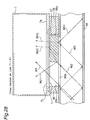
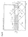
- Fig. 28 shows a cross-sectional view taken along a line T1 - T1' of Fig. 27, and Fig. 29 shows a cross-sectional view taken along a line T2 - T2' of Fig. 27.
- solid dielectrics 27 and 27' are inserted in the microwave waveguides 36a and 36a', respectively, on the termination side of the rectangular waveguide 58 where the radiation field of the microwave is relatively strong.
- the dielectrics 27 and 27' a substance that does not absorb the microwave as described before, the microwave is partly reflected by the dielectrics 27 and 27' and the remaining microwave is transmitted through the dielectrics 27 and 27' so as to reach the window 7c of the plasma chamber 7.
- the radiation field of microwave in the plasma chamber 7 results in a distribution showing higher intensities on the termination side of the rectangular waveguides 58 and 58'.
- Advantageous effects produced by inserting the dielectrics 27 and 27' at positions where the electric field intensity of the microwave is relatively strong are described below for the upper microwave waveguide 36a and the lower microwave waveguide 36a' separately.
- a microwave W2 is reflected by the dielectric 27, the reflected microwave becomes a microwave W21, while the remaining microwave is transmitted through the dielectric 27 so as to become a microwave W22.
- the microwave W21 acts to intensify the originally weak portions-of the microwave within the plasma chamber 7, whereas the microwave W22, conversely, has been attenuated to a microwave power less than that of the microwave W2, acting to weaken the originally strong portions of the microwave in the plasma chamber 7.
- a microwave W31 reflected by the dielectric 27 is further reflected by the movable short-circuit plate provided in the terminating portion of the rectangular waveguide 58, and then the reflected microwave is finally supplied to the plasma chamber 7.
- a microwave W32 transmitted by the dielectric 27 has been attenuated to a less microwave power, like the microwave W22, so that the microwave W32 acts to weaken the originally strong portions of the microwave. Therefore, the distribution of the electric field of the microwave radiated into the plasma chamber 7 is a distribution shown by a broken line of Fig. 30, which is more uniform than that of when the dielectric 27 is not inserted.
- a microwave W2' is reflected by the dielectric 27, the reflected microwave becomes a microwave W21', while the remaining microwave is transmitted through the dielectric so as to become a microwave W22'.
- the microwave W21' acts to intensify the originally weak portions of the microwave within the plasma chamber 7, whereas the microwave W22', conversely, has been attenuated to a microwave power less than that of the microwave W2', acting to weaken the originally strong portions of the microwave, in the plasma chamber 7.
- a microwave W31' reflected by the dielectric 27' is further reflected by the movable short-circuit plate provided in the terminating portion of the rectangular waveguide 58', and the reflected microwave is finally supplied to the plasma chamber 7.
- the microwave W32' transmitted through the dielectric 27' has been attenuated to a less microwave power, like the microwave W22', so that the microwave acts to weaken the originally strong portions of the microwaves. Therefore, the distribution of the electric field intensity of the microwaves radiated into the plasma chamber 7 is a distribution shown by a one-dotted chain line of Fig. 30, more uniform than that when the dielectric 27' is not inserted.
- the long slots 58b and 58b' provided in the rectangular waveguides 58 and 58', respectively, are shifted in the waveguide-axis direction from each other by (1/4) ⁇ 0 or (3/4) ⁇ 0, the resultant electric field distribution of the microwaves is substantially uniform in the waveguide-axis direction as shown by a solid line of Fig. 30.
- Fig. 31 is a schematic construction view showing a tenth preferred embodiment according to the present invention in which the second preferred embodiment and the eighth preferred embodiment are combined together.
- Rectangular waveguides 58 and 58', a microwave waveguide forming member 36, and a plasma chamber 7 are arranged in the same way as that in the second preferred embodiment, except for magnetic-field generators designated by 10a and 10b.
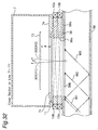
- Figs. 32 and 33 show a cross-sectional view taken along the line T1 - T1' of Fig. 31 and a cross-sectional view taken along the line T2 - T2' of Fig. 31, respectively.
- the magnetic-field generators 10a and 10b each comprise an air-core coil connected to a power supply, and are provided so as to surround the microwave waveguides 36a and 36a' in such a state that the center axes of the air-core coils of the magnetic-field generators 10a and 10b are intersected by each other by ⁇ (rad).
- ⁇ rad
- a magnetic field whose magnitude is a constant and whose lines of magnetic force continuously change from a solid line H1 to-broken line H2, that is, an oscillating magnetic field can be developed to a space between the window 7c of the plasma chamber 7 and the object 13 to be processed.
- Electrons and ions in the plasma generated within the plasma chamber 7 are supplied to the object 13 under constraint by these lines of magnetic force. That is, by changing the lines of magnetic force with time and space, non-uniform plasma can be projected in an evenly equal amount of plasma radiation onto the object 13 to be processed, and then, the uniformity of plasma processing can be further improved.
- the angle ⁇ (rad) formed by the center axes of the magnetic-field generators 10a and 10b is preferably set so as to meet the following relational equation: d ⁇ ⁇ ⁇ 0/2 where d is the distance from the microwave transmitting window 11 to the object 13 to be processed, and ⁇ 0 is the free-space wavelength of the microwave.
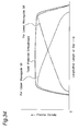
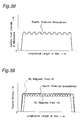
- a plasma density distribution due to a microwave radiated from the long slot 58b of the upper rectangular waveguide 58 and an oscillating magnetic field is shown by a broken line
- a plasma density distribution due to a microwave radiated from the long slot 58b' of the lower rectangular waveguide 58' and an oscillating magnetic field is shown by a one-dot chain line.
- a plasma density distribution as a result of the present preferred embodiment using the two long slots 58b and 58b' is shown by a solid line.
- a plasma density distribution which is more uniform along the longitudinal direction of the plasma chamber 7 can be obtained.
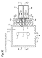
- Fig. 35 is a schematic construction view of a plasma processing apparatus of an eleventh preferred embodiment according to the present invention in which the second preferred embodiment, the fifth preferred embodiment, and the eighth preferred embodiment are combined together.
- a microwave waveguide forming member 36 electrically connects the rectangular waveguides 58 and 58' with the plasma chamber 7, and the cross section of each of the microwave waveguides 36a and 36a' is a narrow rectangular shape, which is identical to that of the long slots 58b and 58b'.
- solid dielectrics 27 and 27' are inserted on the termination side of the rectangular waveguides 58 and 58', respectively, where the radiation electric field intensities of the microwave are relatively strong.
- the dielectrics 27 and 27' are constructed and arranged in the same way as that in the fifth preferred embodiment.
- the magnetic-field generators 10a and 10b each comprise an air-core coil connected to a power supply, and are provided so as to surround the microwave waveguides 36a and 36a' such that the center axes of the generators 10a and 10b are intersected by each other by ⁇ (rad).
- the magnetic-field generators 10a and 10b are used for attaining more uniformity of the plasma density distribution.
- the principle for making the plasma density uniform and the method of setting the angle ⁇ (rad) effective to the uniformity are similar to those in the eighth preferred embodiment.
- a plasma density distribution obtained by the present preferred embodiment is similar to the distribution shown by a solid line of Fig. 34. Thus, a plasma density distribution with a good uniformity can be obtained.
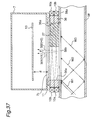
- Fig. 36 is a longitudinal cross-sectional view of a plasma chamber 7 and a rectangular waveguide 58 for coupling with the plasma chamber 7, showing a twelfth preferred embodiment according to the present invention, in which the fifth preferred embodiment and the eighth preferred embodiment are combined together.
- a microwave is introduced to the rectangular waveguide 58 from a microwave power supply through an isolator, a directional coupler, an automatic impedance matching device, and a corner rectangular waveguide. Further, a terminating unit equipped with a movable short-circuit plate is provided at a terminating end of the rectangular waveguide 58.
- a microwave circuit of this twelfth preferred embodiment has the same constitution as that of Fig. 1 showing the first preferred embodiment.
- a microwave waveguide forming member 36 electrically connects the rectangular waveguide 58 with the plasma chamber 7, and the cross section of each of the microwave waveguide 36a is a narrow rectangular shape, which is identical to that of the long slot 58b.
- Fig. 37 is a cross-sectional view taken along a line T - T' of Fig. 36.
- a solid dielectric 27 is inserted into the microwave waveguide 36a at a portion where the radiation field of the microwave radiated toward the plasma chamber 7 is relatively strong, that is, on the termination side of the rectangular waveguide 58.
- the dielectric 27 By selecting as the dielectric 27 a substance that does not absorb the microwave as described before, a microwave is partly reflected by the dielectric 27, while the remaining microwave is transmitted through the dielectric 27 so as to reach the window 7c of the plasma chamber 7. Therefore, the dielectric 27 functions to intensify the originally weak portions of the microwaves in the plasma chamber 7 and to weaken the originally strong portions of the microwaves.
- the principle for obtaining a uniform electric field intensity distribution of the microwaves in the plasma chamber 7 by the insertion of the dielectric 27 is the same as that in the fifth preferred embodiment.
- the magnetic-field generators 10a and 10b each comprise an air-core coil connected to a power supply, and are provided on the outer periphery of the microwave waveguide 36a in such a state that the center axes of the generators 10a and 10b are intersected by each other by ⁇ (rad).
- ⁇ rad
- currents having different phases by 90° from each other and being half-wave-rectified as predetermined in the eighth preferred embodiment are passed through the magnetic-field generators 10a and 10b, a magnetic field whose magnitude is a constant and whose lines of magnetic force continuously change from a broken line H1 to a broken line H2, that is, an oscillating magnetic field can be developed to a space between the window 7c of the plasma chamber 7 and the object 13 to be processed.
- Electrons and ions in the plasma generated within the plasma chamber. 7 are supplied to the object 13 under constraint by these lines of magnetic force. That is, by changing the lines of magnetic force with time and space, non-uniform plasma can be projected in an evenly equal amount of plasma radiation onto the object 13 to be processed, and then the uniformity of plasma processing can be further improved.
- Fig. 38 shows an electric field intensity of a microwave radiated to the plasma chamber 7.
- the angle ⁇ (rad) formed by the center axes of the magnetic-field generators 10a and 10b is preferably set so as to meet the following relational equation: d ⁇ ⁇ ⁇ 0/2 where d is the distance from the microwave transmitting window 11 to the object 13 to be processed, and ⁇ 0 is the free-space wavelength of the microwaves.
- the microwave is supplied to one end of the rectangular waveguide 18.
- the present invention is not limited to this, however, it may be possible that the terminating unit 19 connected to another end of the rectangular waveguide 18 is removed and, instead of this, another microwave power supply is also connected to another end thereof, and then the microwave is supplied to both ends of the rectangular waveguide 18. In this case, the same function and advantageous effects as those in the second preferred embodiment can be obtained.
- two long slots 18b and 18c or 28b and 28b' are provided in one rectangular waveguide 18 or two rectangular waveguides 28 and 28', respectively.
- the present invention is not limited to this, however, three or more long slots may be provided. In this case, adjacent long slots are positioned so as to be shifted from each other by ⁇ (2n-1)/4 ⁇ 0 (where n is a natural number).
- three or more rectangular waveguides may be provided.
- adjacent long slots are positioned so as to be shifted from each other by ⁇ (2n-1)/4 ⁇ 0 (where n is a natural number), and yet a microwave power supply, an isolator, a corner rectangular waveguide, a directional coupler, and an automatic impedance matching device are provided so that the microwaves are supplied to adjacent rectangular waveguides in directions different from each other and parallel to each other.
- two rectangular waveguides 38 and 38' are provided.
- the present invention is not limited to this, however, three or more rectangular waveguides may be provided.
- one rectangular waveguide 48 is provided.
- the present invention is not limited to this, however, two or more rectangular waveguides may be provided.
- one long slot is provided in one rectangular waveguide.
- the present invention is not limited to this, however, two or more long slots may be also provided in one rectangular waveguide. Further, in such a case, the number of rectangular waveguides may be three or more.
Landscapes
- Physics & Mathematics (AREA)
- Engineering & Computer Science (AREA)
- Plasma & Fusion (AREA)
- Chemical & Material Sciences (AREA)
- Analytical Chemistry (AREA)
- Plasma Technology (AREA)
- Drying Of Semiconductors (AREA)
Applications Claiming Priority (2)
| Application Number | Priority Date | Filing Date | Title |
|---|---|---|---|
| JP24840894 | 1994-09-16 | ||
| JP248408/94 | 1994-09-16 |
Publications (2)
| Publication Number | Publication Date |
|---|---|
| EP0702393A2 true EP0702393A2 (fr) | 1996-03-20 |
| EP0702393A3 EP0702393A3 (fr) | 1997-03-26 |
Family
ID=17177676
Family Applications (1)
| Application Number | Title | Priority Date | Filing Date |
|---|---|---|---|
| EP95306404A Ceased EP0702393A3 (fr) | 1994-09-16 | 1995-09-13 | Appareil de traitement par plasma pour introduire une onde micrométrique issue d'un guide d'onde rectangulaire, à travers une feute allongée dans la chambre à plasma |
Country Status (2)
| Country | Link |
|---|---|
| US (1) | US5843236A (fr) |
| EP (1) | EP0702393A3 (fr) |
Cited By (6)
| Publication number | Priority date | Publication date | Assignee | Title |
|---|---|---|---|---|
| DE19722272A1 (de) * | 1997-05-28 | 1998-12-03 | Leybold Systems Gmbh | Vorrichtung zur Erzeugung von Plasma |
| WO2000043568A1 (fr) * | 1999-01-22 | 2000-07-27 | Toyo Kohan Co., Ltd. | Appareil de depot chimique en phase vapeur a plasma par micro-ondes |
| EP0911862A3 (fr) * | 1997-10-20 | 2000-12-27 | Sumitomo Metal Industries Limited | Appareil et procédé de traitement par plasma micro-onde |
| EP1494512A4 (fr) * | 2002-04-09 | 2006-09-13 | Ntt Afty Corp | Source de plasma ecr et dispositif a plasma ecr |
| NO20180654A1 (en) * | 2018-05-08 | 2019-11-11 | Bergen Teknologioverfoering As | Large area PCVD reactor apparatus and method for providing same |
| RU2804043C1 (ru) * | 2023-05-24 | 2023-09-26 | Общество с ограниченной ответственностью Научно-производственная компания "Спектр" | Свч плазменный реактор |
Families Citing this family (32)
| Publication number | Priority date | Publication date | Assignee | Title |
|---|---|---|---|---|
| US6209482B1 (en) * | 1997-10-01 | 2001-04-03 | Energy Conversion Devices, Inc. | Large area microwave plasma apparatus with adaptable applicator |
| US6204606B1 (en) * | 1998-10-01 | 2001-03-20 | The University Of Tennessee Research Corporation | Slotted waveguide structure for generating plasma discharges |
| US6263830B1 (en) * | 1999-04-12 | 2001-07-24 | Matrix Integrated Systems, Inc. | Microwave choke for remote plasma generator |
| JP3650025B2 (ja) * | 2000-12-04 | 2005-05-18 | シャープ株式会社 | プラズマプロセス装置 |
| JP4163432B2 (ja) * | 2002-03-26 | 2008-10-08 | 矢崎総業株式会社 | プラズマ処理装置 |
| KR100485160B1 (ko) * | 2003-01-30 | 2005-04-22 | 동부아남반도체 주식회사 | 반도체 소자의 접속홀 형성 방법 |
| US20070054064A1 (en) * | 2003-12-26 | 2007-03-08 | Tadahiro Ohmi | Microwave plasma processing method, microwave plasma processing apparatus, and its plasma head |
| US7806077B2 (en) * | 2004-07-30 | 2010-10-05 | Amarante Technologies, Inc. | Plasma nozzle array for providing uniform scalable microwave plasma generation |
| CN101583837B (zh) * | 2005-09-22 | 2012-02-15 | 伊斯曼化学公司 | 具有开缝阵列波导的微波反应器 |
| WO2007038196A2 (fr) * | 2005-09-22 | 2007-04-05 | Eastman Chemical Company | Reacteur a micro-ondes comprenant un guide d'onde a reseau de fentes couple a un coude de guide d'onde |
| JP4873405B2 (ja) * | 2006-03-24 | 2012-02-08 | 東京エレクトロン株式会社 | プラズマ処理装置と方法 |
| JP4850592B2 (ja) * | 2006-06-14 | 2012-01-11 | 東京エレクトロン株式会社 | プラズマ処理装置およびプラズマ処理方法 |
| WO2008089147A2 (fr) | 2007-01-15 | 2008-07-24 | Cha Corporation | Destruction induite par micro-ondes de siloxanes et de sulfure d'hydrogène dans un biogaz |
| US7641874B2 (en) * | 2007-01-15 | 2010-01-05 | Cha Corporation | Microwave induced destruction of impurities from biogas and nitrogen oxides from engine exhaust |
| JP5376816B2 (ja) * | 2008-03-14 | 2013-12-25 | 東京エレクトロン株式会社 | マイクロ波導入機構、マイクロ波プラズマ源およびマイクロ波プラズマ処理装置 |
| WO2010129901A2 (fr) | 2009-05-08 | 2010-11-11 | Vandermeulen Peter F | Procédés et systèmes pour dépôt et traitement par plasma |
| WO2011137371A2 (fr) * | 2010-04-30 | 2011-11-03 | Applied Materials, Inc. | Système de dépôt en phase vapeur en ligne vertical |
| TW201141316A (en) * | 2010-05-04 | 2011-11-16 | Ind Tech Res Inst | A linear-type microwave plasma source using rectangular waveguide with a biased slot as the plasma reactor |
| CN102254776A (zh) * | 2010-05-19 | 2011-11-23 | 财团法人工业技术研究院 | 具有偏心开槽可变介质导波管的线型微波等离子体源 |
| US20120160839A1 (en) | 2010-12-23 | 2012-06-28 | Eastman Chemical Company | Microwave wood heater with enhanced spatial usage efficiency and uniformity of heat distribution |
| US9397380B2 (en) * | 2011-01-28 | 2016-07-19 | Applied Materials, Inc. | Guided wave applicator with non-gaseous dielectric for plasma chamber |
| JP5921241B2 (ja) * | 2011-03-10 | 2016-05-24 | 国立大学法人名古屋大学 | プラズマ生成装置、プラズマ処理装置及びプラズマ処理方法 |
| CN103636059B (zh) * | 2011-06-24 | 2016-01-27 | 雷卡邦股份有限公司 | 微波谐振腔 |
| NL2007968C2 (en) | 2011-12-14 | 2013-06-17 | Draka Comteq Bv | An apparatus for performing a plasma chemical vapour deposition process. |
| US9793095B2 (en) * | 2013-03-14 | 2017-10-17 | Tokyo Electron Limited | Microwave surface-wave plasma device |
| JP6288624B2 (ja) * | 2016-06-20 | 2018-03-07 | 東京エレクトロン株式会社 | マイクロ波供給装置、プラズマ処理装置、及び、プラズマ処理方法 |
| US10861667B2 (en) | 2017-06-27 | 2020-12-08 | Peter F. Vandermeulen | Methods and systems for plasma deposition and treatment |
| CN111033689B (zh) | 2017-06-27 | 2023-07-28 | 彼得·F·范德莫伊伦 | 用于等离子体沉积和处理的方法及系统 |
| JP7360934B2 (ja) * | 2019-12-25 | 2023-10-13 | 東京エレクトロン株式会社 | プラズマ処理装置及びプラズマ処理方法 |
| US12318499B2 (en) | 2020-03-13 | 2025-06-03 | Peter F. Vandermeulen | Methods and systems for medical plasma treatment and generation of plasma activated media |
| US12119207B2 (en) * | 2021-08-20 | 2024-10-15 | Tokyo Electron Limited | Apparatus for plasma processing |
| CN115354311A (zh) * | 2022-07-15 | 2022-11-18 | 杭州电子科技大学 | 复合左右手波导的缝隙阵列天线表面波等离子沉积装置 |
Citations (1)
| Publication number | Priority date | Publication date | Assignee | Title |
|---|---|---|---|---|
| JPH05335095A (ja) | 1992-03-30 | 1993-12-17 | Daihen Corp | プラズマ処理装置 |
Family Cites Families (13)
| Publication number | Priority date | Publication date | Assignee | Title |
|---|---|---|---|---|
| US3577207A (en) * | 1969-05-07 | 1971-05-04 | Vladimir Pavlovich Kirjushin | Microwave plasmatron |
| GB2142476A (en) * | 1983-06-29 | 1985-01-16 | Decca Ltd | Slot waveguide radiator |
| JPS61131454A (ja) * | 1984-11-30 | 1986-06-19 | Fujitsu Ltd | マイクロ波プラズマ処理方法と装置 |
| JPH01198478A (ja) * | 1988-02-01 | 1989-08-10 | Canon Inc | マイクロ波プラズマcvd装置 |
| DE9013937U1 (de) * | 1990-10-06 | 1992-02-06 | Röhm GmbH, 64293 Darmstadt | Mikrowellenstrahler |
| WO1992014861A1 (fr) * | 1991-02-26 | 1992-09-03 | Idemitsu Petrochemical Co., Ltd. | Dispositif de deposition en phase vapeur par procede chimique du type a plasma hyperfrequence et procede de synthese du diamant au moyen d'un tel dispositif |
| WO2004089046A1 (fr) * | 1991-11-05 | 2004-10-14 | Nobumasa Suzuki | Appareil d'introduction d'ondes ultracourtes comportant un guide d'onde en forme d'anneau sans fin et installation de traitement au plasma comprenant cet appareil |
| FR2693619B1 (fr) * | 1992-07-08 | 1994-10-07 | Valeo Vision | Dispositif pour le dépôt de polymère par l'intermédiaire d'un plasma excité par micro-ondes. |
| DE4235410C2 (de) * | 1992-10-21 | 1995-06-14 | Troester Maschf Paul | Abgleichvorrichtung für die Mikrowellenübertragung in einem Hohlleiter |
| DE4235914A1 (de) * | 1992-10-23 | 1994-04-28 | Juergen Prof Dr Engemann | Vorrichtung zur Erzeugung von Mikrowellenplasmen |
| US5324553A (en) * | 1993-04-30 | 1994-06-28 | Energy Conversion Devices, Inc. | Method for the improved microwave deposition of thin films |
| JP2833983B2 (ja) * | 1993-12-14 | 1998-12-09 | 日本電気株式会社 | 導波管スロットアレーアンテナ |
| DE9405808U1 (de) * | 1994-04-11 | 1994-06-09 | Süßmuth, Norbert, Dipl.-Ing., 38106 Braunschweig | Plasma-Bearbeitungsgerät |
-
1995
- 1995-09-13 EP EP95306404A patent/EP0702393A3/fr not_active Ceased
- 1995-09-15 US US08/529,282 patent/US5843236A/en not_active Expired - Fee Related
Patent Citations (1)
| Publication number | Priority date | Publication date | Assignee | Title |
|---|---|---|---|---|
| JPH05335095A (ja) | 1992-03-30 | 1993-12-17 | Daihen Corp | プラズマ処理装置 |
Cited By (10)
| Publication number | Priority date | Publication date | Assignee | Title |
|---|---|---|---|---|
| DE19722272A1 (de) * | 1997-05-28 | 1998-12-03 | Leybold Systems Gmbh | Vorrichtung zur Erzeugung von Plasma |
| EP0911862A3 (fr) * | 1997-10-20 | 2000-12-27 | Sumitomo Metal Industries Limited | Appareil et procédé de traitement par plasma micro-onde |
| WO2000043568A1 (fr) * | 1999-01-22 | 2000-07-27 | Toyo Kohan Co., Ltd. | Appareil de depot chimique en phase vapeur a plasma par micro-ondes |
| EP1494512A4 (fr) * | 2002-04-09 | 2006-09-13 | Ntt Afty Corp | Source de plasma ecr et dispositif a plasma ecr |
| US7485204B2 (en) | 2002-04-09 | 2009-02-03 | Mes Afty Corporation | ECR plasma source and ECR plasma device |
| NO20180654A1 (en) * | 2018-05-08 | 2019-11-11 | Bergen Teknologioverfoering As | Large area PCVD reactor apparatus and method for providing same |
| WO2019216772A1 (fr) | 2018-05-08 | 2019-11-14 | Bergen Teknologioverføring As | Appareil cvd à plasma à micro-ondes à grande surface et procédé correspondant pour fournir un tel dépôt |
| NO345052B1 (en) * | 2018-05-08 | 2020-09-07 | Bergen Teknologioverfoering As | Large area microwave plasma chemical vapour deposition (la mpcvd) reactor apparatus and method for providing same |
| US12437971B2 (en) | 2018-05-08 | 2025-10-07 | Vestlandets Innovasjonsselskap As | Large area microwave plasma CVD apparatus |
| RU2804043C1 (ru) * | 2023-05-24 | 2023-09-26 | Общество с ограниченной ответственностью Научно-производственная компания "Спектр" | Свч плазменный реактор |
Also Published As
| Publication number | Publication date |
|---|---|
| US5843236A (en) | 1998-12-01 |
| EP0702393A3 (fr) | 1997-03-26 |
Similar Documents
| Publication | Publication Date | Title |
|---|---|---|
| US5843236A (en) | Plasma processing apparatus for radiating microwave from rectangular waveguide through long slot to plasma chamber | |
| US6396034B2 (en) | Method and apparatus for electromagnetic exposure of planar or other materials | |
| US6155199A (en) | Parallel-antenna transformer-coupled plasma generation system | |
| KR100687057B1 (ko) | 플라즈마 생성장치 및 플라즈마 처리장치 | |
| JP2004235562A (ja) | プラズマ処理装置 | |
| US6087778A (en) | Scalable helicon wave plasma processing device with a non-cylindrical source chamber having a serpentine antenna | |
| US4409595A (en) | Stripline slot array | |
| US20040155829A1 (en) | Slot aray antenna and plasma processing apparatus | |
| US5757331A (en) | Leakage dielectric waveguide and plane antenna using said leakage dielectric waveguide | |
| US6888115B2 (en) | Cascaded planar exposure chamber | |
| US20050067934A1 (en) | Discharge apparatus, plasma processing method and solar cell | |
| EP0564082B1 (fr) | Appareil de traitement à plasma pour générer un plasma uniforme en forme de bande | |
| JPH11162956A (ja) | プラズマ処理装置 | |
| RU2120681C1 (ru) | Устройство для микроволновой вакуумно-плазменной с электронно-циклотронным резонансом обработки конденсированных сред | |
| JP4057541B2 (ja) | プラズマ発生システム | |
| JPH08138889A (ja) | プラズマ処理装置 | |
| KR100197113B1 (ko) | 장방형 도파관에서 긴 슬롯을 통해 플라즈마실에 마이크로웨이브를 조사하는 플라즈마 처리장치 | |
| JPH10275696A (ja) | プラズマ処理装置 | |
| Baum | Sidewall waveguide slot antenna for high power | |
| EP1771921A1 (fr) | Antenne beverage de fuite a large bande | |
| Chen et al. | Aperture-coupled microstrip second higher order leaky-mode antenna | |
| JP3878267B2 (ja) | プラズマ処理装置 | |
| JP3736054B2 (ja) | プラズマ処理装置 | |
| JP3889906B2 (ja) | マイクロ波プラズマ処理装置 | |
| JPH11508724A (ja) | 非円筒形ソースチャンバを有したスケーラブルヘリコン波プラズマ処理装置 |
Legal Events
| Date | Code | Title | Description |
|---|---|---|---|
| PUAI | Public reference made under article 153(3) epc to a published international application that has entered the european phase |
Free format text: ORIGINAL CODE: 0009012 |
|
| 17P | Request for examination filed |
Effective date: 19951002 |
|
| AK | Designated contracting states |
Kind code of ref document: A2 Designated state(s): DE GB |
|
| PUAL | Search report despatched |
Free format text: ORIGINAL CODE: 0009013 |
|
| AK | Designated contracting states |
Kind code of ref document: A3 Designated state(s): DE GB |
|
| 17Q | First examination report despatched |
Effective date: 19981104 |
|
| GRAG | Despatch of communication of intention to grant |
Free format text: ORIGINAL CODE: EPIDOS AGRA |
|
| STAA | Information on the status of an ep patent application or granted ep patent |
Free format text: STATUS: THE APPLICATION HAS BEEN REFUSED |
|
| 18R | Application refused |
Effective date: 20011125 |