EP0702419A1 - Verbesserten Antrieb, insbesondere ein piezoelektrischer Motor - Google Patents
Verbesserten Antrieb, insbesondere ein piezoelektrischer Motor Download PDFInfo
- Publication number
- EP0702419A1 EP0702419A1 EP95402105A EP95402105A EP0702419A1 EP 0702419 A1 EP0702419 A1 EP 0702419A1 EP 95402105 A EP95402105 A EP 95402105A EP 95402105 A EP95402105 A EP 95402105A EP 0702419 A1 EP0702419 A1 EP 0702419A1
- Authority
- EP
- European Patent Office
- Prior art keywords
- transducer according
- signal
- fixed element
- sensor
- amplitude
- Prior art date
- Legal status (The legal status is an assumption and is not a legal conclusion. Google has not performed a legal analysis and makes no representation as to the accuracy of the status listed.)
- Withdrawn
Links
- 238000006073 displacement reaction Methods 0.000 claims abstract description 16
- 230000005284 excitation Effects 0.000 claims description 57
- 230000000750 progressive effect Effects 0.000 claims description 26
- 238000005259 measurement Methods 0.000 claims description 15
- 230000010363 phase shift Effects 0.000 claims description 14
- 238000012937 correction Methods 0.000 claims description 3
- 230000007423 decrease Effects 0.000 claims description 3
- 230000004927 fusion Effects 0.000 claims description 3
- 230000009467 reduction Effects 0.000 claims description 3
- 239000000853 adhesive Substances 0.000 claims description 2
- 230000001070 adhesive effect Effects 0.000 claims description 2
- 238000000034 method Methods 0.000 claims description 2
- 230000008569 process Effects 0.000 claims description 2
- 230000004044 response Effects 0.000 claims description 2
- 239000000919 ceramic Substances 0.000 description 25
- 230000010287 polarization Effects 0.000 description 5
- 238000004519 manufacturing process Methods 0.000 description 4
- 238000010586 diagram Methods 0.000 description 3
- 230000000737 periodic effect Effects 0.000 description 3
- 229910000859 α-Fe Inorganic materials 0.000 description 3
- 238000013459 approach Methods 0.000 description 2
- 230000008901 benefit Effects 0.000 description 2
- 238000013461 design Methods 0.000 description 2
- 235000021183 entrée Nutrition 0.000 description 2
- 239000000463 material Substances 0.000 description 2
- 230000001131 transforming effect Effects 0.000 description 2
- 241000782128 Albizia adianthifolia Species 0.000 description 1
- 241000283070 Equus zebra Species 0.000 description 1
- 241001415961 Gaviidae Species 0.000 description 1
- 230000005355 Hall effect Effects 0.000 description 1
- 241000135309 Processus Species 0.000 description 1
- 230000004913 activation Effects 0.000 description 1
- 230000006399 behavior Effects 0.000 description 1
- 230000008859 change Effects 0.000 description 1
- 238000006243 chemical reaction Methods 0.000 description 1
- 230000008602 contraction Effects 0.000 description 1
- 125000004122 cyclic group Chemical group 0.000 description 1
- 238000001514 detection method Methods 0.000 description 1
- 230000000694 effects Effects 0.000 description 1
- 229920001971 elastomer Polymers 0.000 description 1
- 239000000806 elastomer Substances 0.000 description 1
- 230000005684 electric field Effects 0.000 description 1
- 229940082150 encore Drugs 0.000 description 1
- 230000006870 function Effects 0.000 description 1
- 239000003292 glue Substances 0.000 description 1
- 239000000696 magnetic material Substances 0.000 description 1
- 230000005415 magnetization Effects 0.000 description 1
- 230000003287 optical effect Effects 0.000 description 1
- 230000003071 parasitic effect Effects 0.000 description 1
- 238000012545 processing Methods 0.000 description 1
- 230000001902 propagating effect Effects 0.000 description 1
- 230000000284 resting effect Effects 0.000 description 1
- 238000005096 rolling process Methods 0.000 description 1
- 239000000523 sample Substances 0.000 description 1
- 238000010008 shearing Methods 0.000 description 1
- 230000010356 wave oscillation Effects 0.000 description 1
Images




Classifications
-
- H—ELECTRICITY
- H02—GENERATION; CONVERSION OR DISTRIBUTION OF ELECTRIC POWER
- H02N—ELECTRIC MACHINES NOT OTHERWISE PROVIDED FOR
- H02N2/00—Electric machines in general using piezoelectric effect, electrostriction or magnetostriction
- H02N2/10—Electric machines in general using piezoelectric effect, electrostriction or magnetostriction producing rotary motion, e.g. rotary motors
- H02N2/16—Electric machines in general using piezoelectric effect, electrostriction or magnetostriction producing rotary motion, e.g. rotary motors using travelling waves, i.e. Rayleigh surface waves
- H02N2/163—Motors with ring stator
-
- H—ELECTRICITY
- H02—GENERATION; CONVERSION OR DISTRIBUTION OF ELECTRIC POWER
- H02N—ELECTRIC MACHINES NOT OTHERWISE PROVIDED FOR
- H02N2/00—Electric machines in general using piezoelectric effect, electrostriction or magnetostriction
- H02N2/10—Electric machines in general using piezoelectric effect, electrostriction or magnetostriction producing rotary motion, e.g. rotary motors
- H02N2/14—Drive circuits; Control arrangements or methods
- H02N2/142—Small signal circuits; Means for controlling position or derived quantities, e.g. speed, torque, starting, stopping, reversing
Definitions
- the present invention relates to the field of electrical transducers.
- the present invention finds in particular, but not exclusively, application in the production of an actuator capable of moving an indicator hand opposite a dial, in a dashboard of a motor vehicle to provide the driver with various parameters relating to the vehicle, for example its speed, engine temperature, oil level, etc.
- the transducer exploiting a mechanical vibration, preferably ultrasonic, of the type elliptical, preferably consists of a piezoelectric motor or a magnetostrictive motor.
- a driving cell generating an ultrasonic vibration of elliptical type by combination of a vertical component and a transverse component on a driving part.
- a basic cell can be composed of two piezoelectric ceramics superimposed on a support and adapted to work respectively in transverse vibration, that is to say in shearing, and in longitudinal vibration, that is to say in contraction /extension.
- an actuator comprising an ultrasonic vibration motor of elliptical type and a driven part in contact with the motor in which there is further provided a piezo-sensitive detector cell in contact with the driven part, capable of delivering a signal representative of the vibrations received and means capable of measuring the time difference between the excitation signal applied to the motor and the signal delivered by the detector cell resulting from the propagation in the driven part of the vibrations generated by the engine.
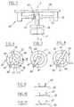
- the frame 10 can be formed for example of a flat printed circuit.
- the printed circuit 10 is provided with a through bore 12 in which is placed a hub 14 centered on an axis O-O.
- the structure of the piezoelectric drive washer 26 and the corresponding control architecture are adapted to generate several wavelengths of the ultrasonic traveling wave in the stator ring 22, ie over the amplitude of displacement. relative allowed between the stator 22 and the rotor 40.
- the stator and the associated control architecture can be adapted to generate a progressive mechanical wave having a wavelength at least equal to the amplitude of relative mechanical displacement authorized between the fixed element and the mobile element, ie for example a single wavelength of the ultrasonic progressive wave in the stator 20, when the latter is capable of rotation over 360 °.
- a progressive mechanical wave having a wavelength at least equal to the amplitude of relative mechanical displacement authorized between the fixed element and the mobile element, ie for example a single wavelength of the ultrasonic progressive wave in the stator 20, when the latter is capable of rotation over 360 °.
- control means are adapted to apply to the motor cells 26, an excitation signal whose frequency is close to the resonant frequency of the motor.
- the amplitude A of the signal coming from the sensor 60 is proportional to the excitation voltage U. However, this amplitude A is all the greater the closer one gets to the mechanical resonance frequency. However, it is desirable to approach this resonance to obtain an optimum displacement of the motor, and a minimum electrical consumption.
- the n piezoelectric motor sectors are preferably equi-distributed around the axis of the motor and separated by equi-distributed intervals each corresponding to the above-mentioned sensor 80 as illustrated in FIG. 3.
- polarized piezoelectric ceramics can simplify the connection architecture of these.
- the invention is not limited to the use of a rotary motor. It can extend to the use of a rectilinear motor.
- the invention applies to any type of ultrasonic traveling wave transducer, in particular to transducers comprising piezoelectric cells or magneto-restrictive cells.
- the invention is not limited to the production of an actuator or motor, but can also find application in the design of sensors.
- the mobile element is forced to move by an external actuating member.
- the position of this mobile element relative to the fixed element is determined by measuring the phase shift between the signal from the sensor 60 linked to the mobile element and the signal linked to the excitation signal.
- This excitation signal can be adapted to generate a progressive mechanical wave, as indicated above.
- the piezoelectric cell 26 placed on the stator can simply receive controlled pulses. In this case the piezoelectric cell 26 can be formed on a single limited sector of the stator.
- the fixed element 20 can be adapted to generate a progressive mechanical wave having several wavelengths, provided that means are provided to limit the amplitude of relative mechanical movement between the fixed element 20 and the movable element 40 at an amplitude less than a wavelength, or that provision is made for removing ambiguity in order to specify the position of the movable element.
- the means of ambiguity can take different forms.
Landscapes
- General Electrical Machinery Utilizing Piezoelectricity, Electrostriction Or Magnetostriction (AREA)
Applications Claiming Priority (2)
| Application Number | Priority Date | Filing Date | Title |
|---|---|---|---|
| FR9411126A FR2724788B1 (fr) | 1994-09-19 | 1994-09-19 | Transducteur a onde mecanique progressive |
| FR9411126 | 1994-09-19 |
Publications (1)
| Publication Number | Publication Date |
|---|---|
| EP0702419A1 true EP0702419A1 (de) | 1996-03-20 |
Family
ID=9467043
Family Applications (2)
| Application Number | Title | Priority Date | Filing Date |
|---|---|---|---|
| EP95402104A Expired - Lifetime EP0702418B1 (de) | 1994-09-19 | 1995-09-19 | Mechanischer Wanderwellenantrieb |
| EP95402105A Withdrawn EP0702419A1 (de) | 1994-09-19 | 1995-09-19 | Verbesserten Antrieb, insbesondere ein piezoelektrischer Motor |
Family Applications Before (1)
| Application Number | Title | Priority Date | Filing Date |
|---|---|---|---|
| EP95402104A Expired - Lifetime EP0702418B1 (de) | 1994-09-19 | 1995-09-19 | Mechanischer Wanderwellenantrieb |
Country Status (3)
| Country | Link |
|---|---|
| EP (2) | EP0702418B1 (de) |
| DE (1) | DE69506502T2 (de) |
| FR (1) | FR2724788B1 (de) |
Cited By (3)
| Publication number | Priority date | Publication date | Assignee | Title |
|---|---|---|---|---|
| EP0790148A1 (de) * | 1996-02-16 | 1997-08-20 | MAGNETI MARELLI S.p.A. | Vorrichtung zum Einstellen von Scheinwerfern mit piezoelektrischem Motor |
| FR2845330A1 (fr) * | 2002-10-04 | 2004-04-09 | Valeo Vision | Dispositif d'eclairage et/ou de signalisation du type projecteur pour vehicule automobile |
| CN117655890A (zh) * | 2023-11-13 | 2024-03-08 | 上海理工大学 | 一种抛光方法可调式高效抛光装置 |
Families Citing this family (1)
| Publication number | Priority date | Publication date | Assignee | Title |
|---|---|---|---|---|
| JP2969447B2 (ja) * | 1998-01-29 | 1999-11-02 | セイコーインスツルメンツ株式会社 | 超音波モータ及び超音波モータの製造方法 |
Citations (7)
| Publication number | Priority date | Publication date | Assignee | Title |
|---|---|---|---|---|
| EP0294102A2 (de) * | 1987-06-04 | 1988-12-07 | Seiko Instruments Inc. | Wanderwellenmotor |
| EP0403298A2 (de) * | 1989-06-15 | 1990-12-19 | Nikon Corporation | Antriebsvorrichtung für Ultraschallwellenmotor |
| EP0424139A2 (de) * | 1989-10-20 | 1991-04-24 | Seiko Epson Corporation | Ultraschallmotor |
| WO1991008594A1 (de) * | 1989-11-29 | 1991-06-13 | Licentia Patent-Verwaltungs-Gmbh | Mehrflächensensorsteuerung für einen wanderwellenmotor |
| EP0442469A1 (de) * | 1990-02-14 | 1991-08-21 | Nikon Corporation | Antriebsvorrichtung für einen Ultraschallwellenmotor |
| JPH0583962A (ja) * | 1991-09-18 | 1993-04-02 | Nec Corp | 振動波モータ装置 |
| FR2685955A1 (fr) * | 1992-01-03 | 1993-07-09 | Jaeger | Actionneur actionne par un moteur a vibration ultrasonore de type elliptique. |
-
1994
- 1994-09-19 FR FR9411126A patent/FR2724788B1/fr not_active Expired - Fee Related
-
1995
- 1995-09-19 EP EP95402104A patent/EP0702418B1/de not_active Expired - Lifetime
- 1995-09-19 DE DE69506502T patent/DE69506502T2/de not_active Expired - Fee Related
- 1995-09-19 EP EP95402105A patent/EP0702419A1/de not_active Withdrawn
Patent Citations (7)
| Publication number | Priority date | Publication date | Assignee | Title |
|---|---|---|---|---|
| EP0294102A2 (de) * | 1987-06-04 | 1988-12-07 | Seiko Instruments Inc. | Wanderwellenmotor |
| EP0403298A2 (de) * | 1989-06-15 | 1990-12-19 | Nikon Corporation | Antriebsvorrichtung für Ultraschallwellenmotor |
| EP0424139A2 (de) * | 1989-10-20 | 1991-04-24 | Seiko Epson Corporation | Ultraschallmotor |
| WO1991008594A1 (de) * | 1989-11-29 | 1991-06-13 | Licentia Patent-Verwaltungs-Gmbh | Mehrflächensensorsteuerung für einen wanderwellenmotor |
| EP0442469A1 (de) * | 1990-02-14 | 1991-08-21 | Nikon Corporation | Antriebsvorrichtung für einen Ultraschallwellenmotor |
| JPH0583962A (ja) * | 1991-09-18 | 1993-04-02 | Nec Corp | 振動波モータ装置 |
| FR2685955A1 (fr) * | 1992-01-03 | 1993-07-09 | Jaeger | Actionneur actionne par un moteur a vibration ultrasonore de type elliptique. |
Non-Patent Citations (1)
| Title |
|---|
| PATENT ABSTRACTS OF JAPAN vol. 017, no. 424 (E - 1410) 6 August 1993 (1993-08-06) * |
Cited By (3)
| Publication number | Priority date | Publication date | Assignee | Title |
|---|---|---|---|---|
| EP0790148A1 (de) * | 1996-02-16 | 1997-08-20 | MAGNETI MARELLI S.p.A. | Vorrichtung zum Einstellen von Scheinwerfern mit piezoelektrischem Motor |
| FR2845330A1 (fr) * | 2002-10-04 | 2004-04-09 | Valeo Vision | Dispositif d'eclairage et/ou de signalisation du type projecteur pour vehicule automobile |
| CN117655890A (zh) * | 2023-11-13 | 2024-03-08 | 上海理工大学 | 一种抛光方法可调式高效抛光装置 |
Also Published As
| Publication number | Publication date |
|---|---|
| FR2724788B1 (fr) | 1997-01-24 |
| DE69506502D1 (de) | 1999-01-21 |
| EP0702418A1 (de) | 1996-03-20 |
| EP0702418B1 (de) | 1998-12-09 |
| DE69506502T2 (de) | 1999-08-12 |
| FR2724788A1 (fr) | 1996-03-22 |
Similar Documents
| Publication | Publication Date | Title |
|---|---|---|
| EP0960361B1 (de) | Uhrwerk mit kapazitiver detektionsvorrichtung | |
| WO2011004120A2 (fr) | Capteur de position absolue et multi-périodique | |
| FR2953805A1 (fr) | Dispositif de pilotage d'un aeronef a elements magneto-sensibles de detection de position angulaire montes hors axe | |
| FR2952430A1 (fr) | Capteur de position magnetique bidirectionnel a rotation de champ | |
| FR2947336A1 (fr) | Dispositif pour determiner le couple et/ou l'angle de rotation d'un arbre | |
| FR2842913A1 (fr) | Dispositif compact de mesure de vitesse et de sens de rotation d'un objet | |
| FR2776064A1 (fr) | Dispositif de mesure de position angulaire utilisant un capteur magnetique | |
| EP0702418B1 (de) | Mechanischer Wanderwellenantrieb | |
| EP0637123B1 (de) | Akustischer Oberflächenwellenmotor | |
| WO2001040736A1 (fr) | Capteur analogique de decalage angulaire sans contact | |
| EP0038744B1 (de) | Schrittmotor, besonders für eine elektronische Uhr | |
| EP0307321A1 (de) | Piezoelektrische gyrometrische Vorrichtung | |
| EP2446228B1 (de) | Winkelpositionssensor | |
| EP0702420B1 (de) | Akustischer Oberflächenwellenmotor | |
| WO2020193344A1 (fr) | Capteur de position inductif de largeur réduite | |
| EP0966049A1 (de) | Piezoelektrischer Motor mit integriertem Positionssensor | |
| EP0279132B1 (de) | Vorrichtung zur Feststellung der Lage einer Vielzahl von Magnetköpfen | |
| EP3708963B1 (de) | System zur bestimmung mindestens eines parameters der rotation eines rotationsorgans | |
| FR3104861A1 (fr) | Dispositif d’horloge | |
| EP0561681B1 (de) | Verfahren zur Bestimmung der Winkellage einer Magnetsonde und Winkelmesseinrichtung | |
| EP0969266A1 (de) | Vorrichtung mit mindestens zwei koaxialen Rädern und mit Mitteln zur Detektion derer Drehwinkellage | |
| FR2611039A1 (fr) | Gyrometre laser, dispositif de suppression des rotations parasites des miroirs mobiles | |
| FR2775396A1 (fr) | Moteur piezoelectrique | |
| FR2874688A1 (fr) | Capteur angulaire equipe de deux curseurs de lecture et vehicule comportant un tel type de capteur | |
| FR3093799A1 (fr) | Système de détermination d’au moins un paramètre de rotation d’un organe tournant |
Legal Events
| Date | Code | Title | Description |
|---|---|---|---|
| PUAI | Public reference made under article 153(3) epc to a published international application that has entered the european phase |
Free format text: ORIGINAL CODE: 0009012 |
|
| AK | Designated contracting states |
Kind code of ref document: A1 Designated state(s): DE ES FR GB IT |
|
| 17P | Request for examination filed |
Effective date: 19960916 |
|
| 17Q | First examination report despatched |
Effective date: 19980330 |
|
| STAA | Information on the status of an ep patent application or granted ep patent |
Free format text: STATUS: THE APPLICATION IS DEEMED TO BE WITHDRAWN |
|
| 18D | Application deemed to be withdrawn |
Effective date: 19990811 |