EP0702460B1 - Konnektor für einschiebbare SIM-Karte - Google Patents
Konnektor für einschiebbare SIM-Karte Download PDFInfo
- Publication number
- EP0702460B1 EP0702460B1 EP95109232A EP95109232A EP0702460B1 EP 0702460 B1 EP0702460 B1 EP 0702460B1 EP 95109232 A EP95109232 A EP 95109232A EP 95109232 A EP95109232 A EP 95109232A EP 0702460 B1 EP0702460 B1 EP 0702460B1
- Authority
- EP
- European Patent Office
- Prior art keywords
- plug
- tray
- sim
- contact base
- coupling device
- Prior art date
- Legal status (The legal status is an assumption and is not a legal conclusion. Google has not performed a legal analysis and makes no representation as to the accuracy of the status listed.)
- Expired - Lifetime
Links
Images

Classifications
-
- G—PHYSICS
- G06—COMPUTING OR CALCULATING; COUNTING
- G06K—GRAPHICAL DATA READING; PRESENTATION OF DATA; RECORD CARRIERS; HANDLING RECORD CARRIERS
- G06K7/00—Methods or arrangements for sensing record carriers, e.g. for reading patterns
- G06K7/0013—Methods or arrangements for sensing record carriers, e.g. for reading patterns by galvanic contacts, e.g. card connectors for ISO-7816 compliant smart cards or memory cards, e.g. SD card readers
- G06K7/0021—Methods or arrangements for sensing record carriers, e.g. for reading patterns by galvanic contacts, e.g. card connectors for ISO-7816 compliant smart cards or memory cards, e.g. SD card readers for reading/sensing record carriers having surface contacts
-
- G—PHYSICS
- G06—COMPUTING OR CALCULATING; COUNTING
- G06K—GRAPHICAL DATA READING; PRESENTATION OF DATA; RECORD CARRIERS; HANDLING RECORD CARRIERS
- G06K13/00—Conveying record carriers from one station to another, e.g. from stack to punching mechanism
- G06K13/02—Conveying record carriers from one station to another, e.g. from stack to punching mechanism the record carrier having longitudinal dimension comparable with transverse dimension, e.g. punched card
- G06K13/08—Feeding or discharging cards
- G06K13/0806—Feeding or discharging cards using an arrangement for ejection of an inserted card
- G06K13/0831—Feeding or discharging cards using an arrangement for ejection of an inserted card the ejection arrangement comprising a slide, carriage or drawer
-
- G—PHYSICS
- G06—COMPUTING OR CALCULATING; COUNTING
- G06K—GRAPHICAL DATA READING; PRESENTATION OF DATA; RECORD CARRIERS; HANDLING RECORD CARRIERS
- G06K19/00—Record carriers for use with machines and with at least a part designed to carry digital markings
- G06K19/06—Record carriers for use with machines and with at least a part designed to carry digital markings characterised by the kind of the digital marking, e.g. shape, nature, code
- G06K19/067—Record carriers with conductive marks, printed circuits or semiconductor circuit elements, e.g. credit or identity cards also with resonating or responding marks without active components
- G06K19/07—Record carriers with conductive marks, printed circuits or semiconductor circuit elements, e.g. credit or identity cards also with resonating or responding marks without active components with integrated circuit chips
- G06K19/077—Constructional details, e.g. mounting of circuits in the carrier
- G06K19/07737—Constructional details, e.g. mounting of circuits in the carrier the record carrier consisting of two or more mechanically separable parts
- G06K19/07739—Constructional details, e.g. mounting of circuits in the carrier the record carrier consisting of two or more mechanically separable parts comprising a first part capable of functioning as a record carrier on its own and a second part being only functional as a form factor changing part, e.g. SIM cards type ID 0001, removably attached to a regular smart card form factor
-
- H—ELECTRICITY
- H01—ELECTRIC ELEMENTS
- H01R—ELECTRICALLY-CONDUCTIVE CONNECTIONS; STRUCTURAL ASSOCIATIONS OF A PLURALITY OF MUTUALLY-INSULATED ELECTRICAL CONNECTING ELEMENTS; COUPLING DEVICES; CURRENT COLLECTORS
- H01R13/00—Details of coupling devices of the kinds covered by groups H01R12/70 or H01R24/00 - H01R33/00
- H01R13/62—Means for facilitating engagement or disengagement of coupling parts or for holding them in engagement
-
- H—ELECTRICITY
- H04—ELECTRIC COMMUNICATION TECHNIQUE
- H04B—TRANSMISSION
- H04B1/00—Details of transmission systems, not covered by a single one of groups H04B3/00 - H04B13/00; Details of transmission systems not characterised by the medium used for transmission
- H04B1/38—Transceivers, i.e. devices in which transmitter and receiver form a structural unit and in which at least one part is used for functions of transmitting and receiving
- H04B1/3816—Mechanical arrangements for accommodating identification devices, e.g. cards or chips; with connectors for programming identification devices
Definitions
- the present invention relates to a coupling device for plug-in subscriber identity modules (abbreviated as SIM) as used in electronic equipment such as mobile telephone, information terminal and the like which require plug-in SIM with IC cards incorporated in chip form.
- SIM subscriber identity modules
- US-PS 5 257 414 concerns a portable telephone including a transceiver having a housing and obtaining subscriber information from a SIM coupled to an electronic apparatus contained within the transceiver.
- Said electronic apparatus forms a SIM chip card chamber into which the SIM chip card is to be inserted for its mechanical accommodation and electrical connection with a SIM chip card reader.
- FIG. 3 A further prior art coupling device for plug-in SIM is illustrated in Fig. 3.
- the coupling device for plug-in SIM is comprised of a contact base 2 and a cover 4.
- One end of the contact base 2 is linked with one end of the cover 4 via a rotating axis 6.
- a connecting terminal 1 is built-in inside the contact base 2.
- Slots 5, wherein a plug-in SIM (not shown in Fig. 3) is inserted, and stoppers 3 are formed on the cover 4.
- the cover 4 opens or closes by rotating around the rotating axis 6. While the cover 4 is kept open, a plug-in SIM is placed in the cover 4 by inserting into the slots 5. Upon closing the cover 4, the stoppers 3 are engaged with the contact base 2 to fasten the cover 4 tightly to the contact base 2, thereby bringing the connecting terminal 1 built in the contact base 2 into contact with the plug-in SIM under a constant pressure applied thereto.
- the cover 4 has to be opened or closed by rotating around the axis thereof, thereby requiring the electronic equipment that uses this coupling device to have structures wherein a large opening had to be provided.
- the object of the present invention is to provide a coupling device for plug-in SIM which makes it possible for the electronic equipment incorporating the plug-in SIM to have the smallest possible structures in the opening that is required for replacement of the plug-in SIM.
- the another object of the present invention is to provide a coupling device for plug-in SIM which makes it possible for the plug-in SIM removed for replacement to be stored in a state wherein the removed plug-in SIM is mounted on a tray.
- a coupling device for plug-in SIM of the present invention comprises a stand-alone tray for accommodating a plug-in SIM and a stand-alone contact base having a connecting terminal.
- the tray accommodates a plug-in SIM.
- the tray accommodating a plug-in SIM is mounted on the contact base when the plug-in SIM is needed, and removed when the plug-in SIM becomes no longer needed.
- the electrodes disposed on the plug-in SIM are in contact with the connecting terminal of the contact base. Conversely, when the tray is dismounted from the contact base, the tray is completely separated from the contact base.
- One of the preferred structures disclosed by the present invention has a guiding means whereby the foregoing tray is inserted into or pulled out of the contact base along the surface thereof.
- a more preferred structure has the foregoing tray provided with a first guiding means on the both sides thereof, respectively, and also has the foregoing contact base provided with a second guiding means on the both sides thereof, respectively, so as to have the mounting and dismounting of the tray performed in such a way wherein the foregoing first guiding means is guided by the second guiding means. It is particularly preferred to employ structures wherein pin-like studs serving as the first guiding means mate with depressed grooves serving as the second guiding means.
- the contact base has a sloping groove at the both ends of the aforementioned grooves in continuation thereof.
- the tray that accommodates a plug-in SIM can be easily dismounted from the contact base thereby facilitating the storage of the plug-in SIM in a state wherein each respective plug-in SIM is put together with the tray, rather than individually separated.
- the structures employing the guiding means make it possible to have the tray moved along the surface of the contact base when the tray is inserted therein.
- the opening required of the electronic equipment, wherein a coupling device of the present invention is incorporated can only be of an area almost equal to the cross-sectional area of the contact base.
- an opening to be provided on electronic equipment for exchanges of plug-in SIM can be designed with the smallest possible area, thereby contributing to miniaturization of the electronic equipment.
- the structures wherein a tray provided with a first guiding means and a contact base provided with a second guiding means are employed, enable the tray to be inserted accurately along the surface of the contact base.
- the tray can be first inserted readily into the contact base along the surface thereof.
- the plug-in SIM held in the contact base is not yet in contact with the connecting terminal.
- the tray is lifted upward perpendicularly to the contact base surface and mounted in the contact base with the contacting terminal thereof brought into contact with the electrodes of the plug-in SIM.
- the plug-in SIM accommodated in the tray does not rub against the connecting terminal incorporated in the contact base.
- the damages inflicted on the connecting terminals are reduced, thereby contributing to the extended life of the connecting terminal. This is also resulting in an increased number of the repeated use of the plug-in SIM.
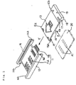
- Fig. 1 is an exploded view of a coupling device for plug-in SIM as an exemplary embodiment of the present invention.
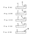
- Fig. 2(A) to Fig. 2(E) show cross-sectional views of the grooves formed on the contact base of a coupling device for plug-in SIM as an exemplary embodiment of the present invention.
- Fig. 3 is a perspective view of a prior art coupling device for plug-in SIM.
- a coupling device for plug-in SIM comprises an almost plate-shaped contact base 12 having a connecting terminal 11, a tray 13 inserted into the contact base 12 and a plug-in SIM 20 having electrodes 21.
- the plug-in SIM 20 is mounted on the tray 13.
- the tray 13 with a plug-in SIM 20 mounted therein is accommodated in the contact base 12 by a movement of the tray 13 in the Y direction along the surface of the almost plate-shaped contact base 12.
- the plug-in SIM 20 is a card with IC chips mounted thereon, and electrodes 21 are disposed at specified places on the surface of the plug-in SIM 20.
- the connecting terminal 11 is incorporated with the contact base 12.
- the connecting terminal 11 is partially embedded inside the contact base 12, contacts 11a of the connecting terminal 11 are exposed to the surface of the contact base 12, and connecting members 11b located at the end of the connecting terminal 11 are sticking out from the end surface of the contact base 12.
- each respective groove 14 has a first sloping groove 14a disposed slantingly at the entrance thereof and also has a second sloping groove 14b disposed slantingly likewise in the farthest end thereof.
- a SIM holding groove 17 serving as a means of accommodating the plug-in SIM.
- the both ends of the plug-in SIM 20 are inserted into the foregoing SIM holding grooves 17 for accommodating the plug-in SIM in the tray 13.
- first pin-like stud 15a On each of the both outer sides of one end of the tray 13 is formed a first pin-like stud 15a and on each of the both outer sides of the other end of the tray 13 is formed a second pin-like stud 15b, both serving as a first guiding means to guide the insertion of the tray 13 into the contact base 12.
- the first guiding means like the foregoing first pin-like studs 15a and second pin-like studs 15b are engaged with the second guiding means like the grooves 14.
- a stopper 16 is formed at the end of the tray 13 which corresponds in position to the entrance of the contact base 12. On a specified position of the tray 13 is formed a hole 19 to hold a hanging means such as a string, chain or the like.
- the SIM holding grooves 17 serve the purposes of guiding and holding the plug-in SIM 20 when the plug-in SIM 20 is installed in the tray 13 by insertion.
- the plug-in SIM 20 is inserted into the tray 13 in the X direction along the SIM holding grooves 17 disposed on the tray 13 and held firmly by SIM stoppers 18.
- the tray 13 accommodating the plug-in SIM 20 is then placed at a specified position inside the contact base 12 by inserting into the contact base 12 in the Y direction while the first pin-like studs 15a of the tray 13 being guided along the two depressed grooves 14 which are provided on the contact base 12.
- the electrodes 21 of the plug-in SIM accommodated in the tray 13 are not yet brought into contact with the contacts 11a of the connecting terminal 11 incorporated in the contact base 12.
- the stopper 16 hits the end surface of the contact base 12, and in that state the tray 13 is held by the contact base 12.
- the electrodes 21 formed on the plug-in SIM 20 are brought into contact with the contacts 11a of the connecting terminal 11 under a steady pressure applied therebetween, and are electrically connected to the contacts lla. between.
- the connecting members 11b at the end of the connecting terminal 11 are electrically connected to the electric circuits of the electronic equipment wherein this coupling device for plug-in SIM is installed.
- the material of the connecting terminal 11 is used, for example, an electro-conductive metallic material, and particularly preferred is the one having spring-like elasticity.
- the connecting terminal 11 is electrically insulated from the contact base 12 wherein the connecting terminal 11 is integrated.
- the material of the contact base 12 is used, for example, a resin material or metallic material.
- the tray 13 is electrically insulated from the plug-in SIM 20 mounted inside thereof.
- the material of the tray 13 is used, for example, a resin material or metallic material.
- the tray 13 is inserted into the almost plate-shaped contact base 12 along the surface thereof, and when the plug-in SIM 20 is exchanged the tray 13 can be taken out of the tray 13 by pulling out along the surface of the contact base 12. Therefore, the opening required of the equipment, wherein a coupling device for plug-in SIM is installed, at the time of exchanging the plug-in SIM 20 can be made very small, thereby contributing effectively to miniaturization of the equipment.
- the plug-in SIM 20 can be stored in a state wherein the plug-in SIM 20 is held by the tray 13.
- the tray 13 can be inserted into the contact base 12 readily and accurately by sliding the tray 13 in the direction along the surface of the contact base 12 because of the structures wherein the first pin-like studs 15a and second pin-like studs 15b are formed on the tray 13 and also the grooves 14 are formed on the contact base 12.
- the tray 13 is first inserted into the contact base 12 along the base lines of the grooves 14 without causing any contacting between the electrodes 21 and connecting terminal 11, and then the tray 13 is guided along the second sloping grooves 14b and first sloping grooves 14a upward in the vertical direction.
- the electrodes 21 and the contacts 11a of the connecting terminal are brought into contact with each other. Therefore, the friction between the electrodes 21 of the plug-in SIM 20 mounted on the tray 13 and the contacts 11a of the connecting terminal 11 integrated with the contact base 12 can be eliminated.
- damages inflicted on the connecting terminal 11 are reduced, thereby extending the life thereof. Also, such an effect as an increased number of the repeated use of the plug-in SIM 20 is realized.
- a means of carrying the tray 13 used in connection with the hole 19 makes it effectively possible for the tray 13 dismounted from the contact base 12 to be carried around with ease. It is needless to say that there are many other variations in the exemplary embodiment of the present invention.
- a groove 14 (having a narrower width at the bottom than at the opening) as shown in Fig. 2(E) is formed on the upper surface of each respective edge of the contact base, pin-like studs mating to the foregoing groove are formed on the lower surface of each respective edge of the tray, and the pin-like studs are guided by the grooves.
- the sloping grooves provided at the both ends of the grooves can be of any shapes as long as the shape employed serves the purpose of guiding the inserted tray upward vertically against the surface of the contact base.
Landscapes
- Engineering & Computer Science (AREA)
- General Physics & Mathematics (AREA)
- Theoretical Computer Science (AREA)
- Physics & Mathematics (AREA)
- Computer Networks & Wireless Communication (AREA)
- Computer Vision & Pattern Recognition (AREA)
- Computer Hardware Design (AREA)
- Microelectronics & Electronic Packaging (AREA)
- Artificial Intelligence (AREA)
- Signal Processing (AREA)
- Coupling Device And Connection With Printed Circuit (AREA)
- Details Of Connecting Devices For Male And Female Coupling (AREA)
- Telephone Set Structure (AREA)
- Transmitters (AREA)
- Mobile Radio Communication Systems (AREA)
- Telephonic Communication Services (AREA)
- Mechanical Coupling Of Light Guides (AREA)
Claims (10)
- Anschlussvorrichtung für einführbare Teilnehmeridentifizierungsmodule SIM, die aufweist:dadurch gekennzeichnet, dassa) einen autonomen Trog bzw. Rahmen (13) zur Aufnahme eines einführbaren SIM-Moduls (20); undb) eine autonome Kontaktbasis (12) mit einem Anschlussterminal (11),
c) der Trog bzw. Rahmen (13) in die Kontaktbasis (12) montierbar oder von der Kontaktbasis lösbar ist. - Anschlussvorrichtung für einführbare Teilnehmeridentifizierungsmodule nach Anspruch 1, dadurch gekennzeichnet, dass an dem Trog bzw. Rahmen (13) eine erste Führungseinrichtung (15a, 15b) ausgebildet ist, an der Kontaktbasis (12) eine zweite Führungseinrichtung (14) ausgebildet ist und der Trog bzw. Rahmen (13) in die Kontaktbasis (12) montierbar oder von ihr lösbar ist, indem die Bewegung der ersten Führungseinrichtung (15a, 15b) von der zweiten Führungseinrichtung (14) geführt wird.
- Anschlussvorrichtung für einführbare Teilnehmeridentifizierungsmodule nach Anspruch 2, dadurch gekennzeichnet, dass stiftähnliche Ansätze (15a, 15b), die an beiden Seitenflächen des Trogs bzw. Rahmens (13) gebildet sind, als die erste Führungseinrichtung dienen und eingelassene Rillen (14), die an beiden Seitenflächen der Kontaktbasis (12) gebildet sind, als die zweite Führungseinrichtung dienen.
- Anschlussvorrichtung für einführbare Teilnehmeridentifizierungsmodule nach einem der Ansprüche 2 oder 3 , dadurch gekennzeichnet, dass der Trog bzw. Rahmen (13) in die Kontaktbasis (12) eingeführt oder aus ihr herausgezogen wird entsprechend der Bewegung der ersten Führungseinrichtung (15a, 15b), die von der zweiten Führungseinrichtung (14) geführt wird.
- Anschlussvorrichtung für einführbare Teilnehmeridentifizierungsmodule nach einem der Ansprüche 1 bis 4, dadurch gekennzeichnet, dassdas einführbare SIM-Modul (20) mit Elektroden (21) versehen ist;der Trog bzw. Rahmen (13), der das einführbare SIM-Modul (20) aufnimmt, in die Kontaktbasis (12) eingeführt oder aus ihr herausgezogen wird durch seine Bewegung entlang der Oberfläche der Kontaktbasis (12);die Elektroden (21) des einführbaren SIM-Moduls (20) mit dem Anschlussterminal (11) in Kontakt gebracht sind, wenn der Trog bzw. Rahmen (13) in die Kontaktbasis (12) eingeführt ist; undder Trog bzw. Rahmen (13), der das einführbare SIM-Modul (20) aufnimmt, von der Kontaktbasis (12) getrennt wird, wenn der Trog bzw. Rahmen (13) aus der Kontaktbasis (12) herausgezogen wird.
- Anschlussvorrichtung für einführbare Teilnehmeridentifizierungsmodule nach einem der Ansprüche 3 bis 5, dadurch gekennzeichnet, dass abfallende Rillen (14a, 14b) an beiden Enden der Rillen (14) ausgebildet sind und an diese anschließen, und dass an dem einführbaren SIM-Modul (20) vorgesehene Elektroden (21) an das Anschlussterminal (11) angeschlossen sind, wenn der Trog bzw. Rahmen (13) in die Kontaktbasis (12) montiert ist.
- Anschlussvorrichtung für einführbare Teilnehmeridentifizierungsmodule nach einem der Ansprüche 1 bis 6, dadurch gekennzeichnet, dass der Trog bzw. Rahmen (13) mit einer Aufnahmeeinrichtung (17) für das einführbare SIM-Modul (20) versehen ist.
- Anschlussvorrichtung für einführbare Teilnehmeridentifizierungsmodule nach Anspruch 7, dadurch gekennzeichnet, dass Rillen (17), die an beiden Enden des Trogs bzw. Rahmens (13) gebildet sind, als die Aufnahmeeinrichtung für das einführbare SIM-Modul (20) dienen.
- Anschlussvorrichtung für einführbare Teilnehmeridentifizierungsmodule nach einem der Ansprüche 1 bis 8, dadurch gekennzeichnet, dass an dem Trog bzw. Rahmen (13) eine Einrichtung (19) zum Anbringen eines Tragematerials vorgesehen ist.
- Anschlussvorrichtung für einführbare Teilnehmeridentifizierungsmodule nach einem der Ansprüche 6 bis 9, dadurch gekennzeichnet, dassa) der Trog bzw. Rahmen (13) eine Aufnahmeeinrichtung (17) aufweist, in der das einführbare SIM-Modul (20) aufgenommen ist;b) das Anschlussterminal (11) Kontakte (11a) und Anschlusselemente (11b) aufweist oder hiervon gebildet wird;c) der Trog bzw. Rahmen (13), der das einführbare SIM-Modul (20) aufnimmt, in die Kontaktbasis (12) eingeführt wird, indem die stiftähnlichen Ansätze (15a, 15b) von den Rillen (14) geführt werden;d) die Elektroden (21) des einführbaren SIM-Moduls (20), das von dem Trog bzw. Rahmen (13) aufgenommen ist, an die Kontakte (11a) des Anschlussterminals (11) angeschlossen werden, indem die stiftähnlichen Ansätze (15a, 15b) von den abfallenden Rillen (14a, 14b) geführt werden; unde) der Trog bzw. Rahmen (13), der das einführbare SIM-Modul (20) aufnimmt, von der Kontaktbasis (12) getrennt wird, wenn der Trog bzw. Rahmen (13) aus der Kontaktbasis (12) herausgezogen wird, wobei die stiftähnlichen Ansätze (15a, 15b) von den Rillen (14) und abfallenden Rillen (14a, 14b) geführt werden.
Priority Applications (1)
| Application Number | Priority Date | Filing Date | Title |
|---|---|---|---|
| EP01103689A EP1133065B1 (de) | 1994-09-16 | 1995-06-14 | Mobilfunktelefon mit einschiebbarem Teilnehmermodul und Konnektor für einschiebbares SIM-Modul |
Applications Claiming Priority (3)
| Application Number | Priority Date | Filing Date | Title |
|---|---|---|---|
| JP22119394 | 1994-09-16 | ||
| JP6221193A JP3068754B2 (ja) | 1994-09-16 | 1994-09-16 | プラグインsimの接続装置 |
| JP221193/94 | 1994-09-16 |
Related Child Applications (1)
| Application Number | Title | Priority Date | Filing Date |
|---|---|---|---|
| EP01103689A Division EP1133065B1 (de) | 1994-09-16 | 1995-06-14 | Mobilfunktelefon mit einschiebbarem Teilnehmermodul und Konnektor für einschiebbares SIM-Modul |
Publications (3)
| Publication Number | Publication Date |
|---|---|
| EP0702460A2 EP0702460A2 (de) | 1996-03-20 |
| EP0702460A3 EP0702460A3 (de) | 1998-02-04 |
| EP0702460B1 true EP0702460B1 (de) | 2003-03-26 |
Family
ID=16762933
Family Applications (2)
| Application Number | Title | Priority Date | Filing Date |
|---|---|---|---|
| EP95109232A Expired - Lifetime EP0702460B1 (de) | 1994-09-16 | 1995-06-14 | Konnektor für einschiebbare SIM-Karte |
| EP01103689A Expired - Lifetime EP1133065B1 (de) | 1994-09-16 | 1995-06-14 | Mobilfunktelefon mit einschiebbarem Teilnehmermodul und Konnektor für einschiebbares SIM-Modul |
Family Applications After (1)
| Application Number | Title | Priority Date | Filing Date |
|---|---|---|---|
| EP01103689A Expired - Lifetime EP1133065B1 (de) | 1994-09-16 | 1995-06-14 | Mobilfunktelefon mit einschiebbarem Teilnehmermodul und Konnektor für einschiebbares SIM-Modul |
Country Status (8)
| Country | Link |
|---|---|
| EP (2) | EP0702460B1 (de) |
| JP (1) | JP3068754B2 (de) |
| CN (1) | CN1082729C (de) |
| AT (2) | ATE235761T1 (de) |
| AU (1) | AU691267B2 (de) |
| DE (2) | DE69530034T2 (de) |
| ES (2) | ES2189812T3 (de) |
| NO (1) | NO307722B1 (de) |
Families Citing this family (30)
| Publication number | Priority date | Publication date | Assignee | Title |
|---|---|---|---|---|
| FR2743464A1 (fr) * | 1996-01-10 | 1997-07-11 | Philips Electronics Nv | Appareil muni d'un boitier amovible contenant un adaptateur permettant la lecture de cartes a puces aux formats differents |
| FR2743463A1 (fr) * | 1996-01-10 | 1997-07-11 | Philips Electronics Nv | Appareil muni d'un adaptateur permettant la lecture de cartes a puces aux formats differents |
| US7925301B2 (en) | 1997-06-03 | 2011-04-12 | Fujitsu Limited | Portable telephone set with a card inserted through a battery holding space |
| GB9822697D0 (en) * | 1998-10-19 | 1998-12-09 | Nokia Mobile Phones Ltd | Data card holder |
| FR2793956B1 (fr) * | 1999-05-21 | 2001-08-17 | Cit Alcatel | Appareil muni dans un boitier d'un verrou pour un insert, boitier comportant un verrou et procede de montage d'un verrou dans un boitier |
| DE19940695B4 (de) * | 1999-08-27 | 2008-03-27 | ITT Manufacturing Enterprises, Inc., Wilmington | Elektronisches Mediagerät |
| JP2001118618A (ja) | 1999-10-18 | 2001-04-27 | Jst Mfg Co Ltd | コネクタ |
| JP4697918B2 (ja) * | 2001-06-22 | 2011-06-08 | 大日本印刷株式会社 | プラグインsimカード用ホルダー |
| JP2003196605A (ja) * | 2001-12-25 | 2003-07-11 | Toshiba Corp | 情報処理装置 |
| KR100469693B1 (ko) * | 2002-10-11 | 2005-02-02 | 엘지전자 주식회사 | 유아이엠 카드 결합장치 |
| FR2837594B1 (fr) * | 2003-02-04 | 2004-07-16 | Canal Plus Technologies | Objet portable a puce |
| FI116325B (fi) | 2003-12-03 | 2005-10-31 | Nokia Corp | Muistikortin kytkentäelin |
| JP4386811B2 (ja) | 2004-08-19 | 2009-12-16 | 日本圧着端子製造株式会社 | メモリカード用ソケット |
| JP4403040B2 (ja) | 2004-08-19 | 2010-01-20 | 日本圧着端子製造株式会社 | Simソケット用カードホルダー |
| JP4640928B2 (ja) * | 2004-11-05 | 2011-03-02 | 大日本印刷株式会社 | Icカードトレイ、icカードトレイを備えたicカードリーダライタ |
| JP4468193B2 (ja) | 2005-01-27 | 2010-05-26 | 日本圧着端子製造株式会社 | カードコネクタ |
| JP4571028B2 (ja) * | 2005-07-11 | 2010-10-27 | 日本圧着端子製造株式会社 | カードコネクタ |
| KR100724850B1 (ko) * | 2006-05-25 | 2007-06-04 | 삼성전자주식회사 | 휴대 단말기의 심카드 착탈 가이드 장치 |
| WO2009075023A1 (ja) * | 2007-12-10 | 2009-06-18 | Renesas Technology Corp. | Simアダプタおよびsimカード |
| JP2009181790A (ja) * | 2008-01-30 | 2009-08-13 | Alps Electric Co Ltd | カード用アダプタ |
| KR101496458B1 (ko) * | 2008-03-26 | 2015-02-26 | 타이코에이엠피(유) | 심 카드의 커넥터 |
| DE102008039515B4 (de) * | 2008-08-23 | 2016-01-07 | Albrecht Jung Gmbh & Co. Kg | Elektrisches Installationsgerät |
| JP2010022024A (ja) * | 2009-09-08 | 2010-01-28 | Fujitsu Ltd | 携帯電話機 |
| JP2010086550A (ja) * | 2009-12-18 | 2010-04-15 | Renesas Technology Corp | 半導体カードデバイス |
| US8264837B2 (en) | 2010-04-19 | 2012-09-11 | Apple Inc. | Systems and methods for cover assembly retention of a portable electronic device |
| CN102709753B (zh) * | 2012-06-08 | 2016-06-08 | 北京盛博协同科技有限责任公司 | 一种cf卡锁紧器 |
| CN103108062B (zh) * | 2013-01-17 | 2015-08-12 | 广东欧珀移动通信有限公司 | 一种sim卡组件和手机 |
| CN106356657B (zh) | 2015-07-20 | 2019-07-09 | 微软技术许可有限责任公司 | 卡连接器及其制造方法 |
| CN105554187A (zh) * | 2015-12-14 | 2016-05-04 | 天津华迈科技有限公司 | 一种方便插卡的手机主板组件 |
| WO2024228481A2 (ko) * | 2023-05-03 | 2024-11-07 | 삼성전자주식회사 | 슬라이딩 가능한 프레임을 갖는 심 어셈블리 및 이를 포함하는 전자 장치 |
Family Cites Families (5)
| Publication number | Priority date | Publication date | Assignee | Title |
|---|---|---|---|---|
| DE4029576C2 (de) * | 1990-09-18 | 1994-12-01 | Amphenol Tuchel Elect | Kontaktiereinrichtung für Standard-Chipkarte und SIM-Karte |
| US5257414A (en) * | 1990-11-26 | 1993-10-26 | Motorola, Inc. | Apparatus for accepting and retaining a memory card |
| FI90298C (fi) * | 1992-02-18 | 1994-01-10 | Nokia Mobile Phones Ltd | Kortinlukijalaite |
| EP0599244B1 (de) * | 1992-11-27 | 1999-04-14 | Denso Corporation | Tragbares elektronisches Gerät |
| DE4243076C2 (de) * | 1992-12-18 | 2000-08-31 | Amphenol Tuchel Elect | Kotaktiereinrichtung für eine Chipkarte |
-
1994
- 1994-09-16 JP JP6221193A patent/JP3068754B2/ja not_active Expired - Fee Related
-
1995
- 1995-03-21 CN CN95102350A patent/CN1082729C/zh not_active Expired - Fee Related
- 1995-05-31 NO NO952149A patent/NO307722B1/no unknown
- 1995-06-01 AU AU20439/95A patent/AU691267B2/en not_active Ceased
- 1995-06-14 AT AT95109232T patent/ATE235761T1/de not_active IP Right Cessation
- 1995-06-14 ES ES95109232T patent/ES2189812T3/es not_active Expired - Lifetime
- 1995-06-14 EP EP95109232A patent/EP0702460B1/de not_active Expired - Lifetime
- 1995-06-14 ES ES01103689T patent/ES2171387T3/es not_active Expired - Lifetime
- 1995-06-14 AT AT01103689T patent/ATE213109T1/de not_active IP Right Cessation
- 1995-06-14 EP EP01103689A patent/EP1133065B1/de not_active Expired - Lifetime
- 1995-06-14 DE DE69530034T patent/DE69530034T2/de not_active Expired - Fee Related
- 1995-06-14 DE DE69525380T patent/DE69525380T2/de not_active Expired - Fee Related
Also Published As
| Publication number | Publication date |
|---|---|
| DE69525380T2 (de) | 2002-10-10 |
| EP0702460A2 (de) | 1996-03-20 |
| ATE235761T1 (de) | 2003-04-15 |
| DE69530034T2 (de) | 2003-09-25 |
| EP0702460A3 (de) | 1998-02-04 |
| ATE213109T1 (de) | 2002-02-15 |
| DE69530034D1 (de) | 2003-04-30 |
| CN1082729C (zh) | 2002-04-10 |
| NO952149D0 (no) | 1995-05-31 |
| EP1133065A1 (de) | 2001-09-12 |
| ES2171387T3 (es) | 2002-09-16 |
| AU691267B2 (en) | 1998-05-14 |
| JP3068754B2 (ja) | 2000-07-24 |
| AU2043995A (en) | 1996-03-28 |
| ES2189812T3 (es) | 2003-07-16 |
| NO307722B1 (no) | 2000-05-15 |
| CN1119355A (zh) | 1996-03-27 |
| EP1133065B1 (de) | 2002-02-06 |
| NO952149L (no) | 1996-03-18 |
| JPH0887582A (ja) | 1996-04-02 |
| DE69525380D1 (de) | 2002-03-21 |
Similar Documents
| Publication | Publication Date | Title |
|---|---|---|
| EP1133065B1 (de) | Mobilfunktelefon mit einschiebbarem Teilnehmermodul und Konnektor für einschiebbares SIM-Modul | |
| RU2215324C2 (ru) | Держатель карточки модуля идентификации абонента (миа) | |
| US7427026B2 (en) | Memory card adapter for connecting a miniature card to a standard card connector, along with a method of fabricating same | |
| US6842336B2 (en) | Portable electronic device with carrier plate | |
| US4354718A (en) | Dual-in-line package carrier and socket assembly | |
| JPH0836622A (ja) | マイクロサーキットカードの読取り装置 | |
| US5259795A (en) | Edge connector for a printed circuit board or the like | |
| US6955546B1 (en) | Electrical connector with shutter | |
| KR100387910B1 (ko) | 부동 가이드 커넥터 및 방법 | |
| US20050112947A1 (en) | Connector for memory cards | |
| US7344401B2 (en) | Surface contact card holder | |
| EP1227549A2 (de) | IC-Kartenverbinder mit elastischem Belag | |
| JPH0850638A (ja) | マイクロサーキットカードの読取り装置 | |
| US7303442B2 (en) | Connector for memory cards | |
| EP1453146B1 (de) | Elektrischer Steckverbinder mit Schutzblende | |
| US7473120B2 (en) | ZIF socket connector with pop-up pick-up cap when cover is moved to open position | |
| US7252231B2 (en) | Card adapter | |
| US20060208077A1 (en) | Memory card connector | |
| US20050245120A1 (en) | Memory card connector with hinged and latched cover | |
| KR100618477B1 (ko) | 메모리 카드 커넥터 | |
| US7252529B2 (en) | Chip card retaining mechanism | |
| US6942513B2 (en) | Card connector | |
| US20060128225A1 (en) | Memory card connector | |
| EP1627342B1 (de) | Speicherkartenverbinder | |
| CA2326789A1 (en) | Improved card reader for mounting to printed circuit board |
Legal Events
| Date | Code | Title | Description |
|---|---|---|---|
| PUAI | Public reference made under article 153(3) epc to a published international application that has entered the european phase |
Free format text: ORIGINAL CODE: 0009012 |
|
| AK | Designated contracting states |
Kind code of ref document: A2 Designated state(s): AT CH DE ES FR IT LI SE |
|
| PUAL | Search report despatched |
Free format text: ORIGINAL CODE: 0009013 |
|
| AK | Designated contracting states |
Kind code of ref document: A3 Designated state(s): AT CH DE ES FR IT LI SE |
|
| 17P | Request for examination filed |
Effective date: 19980403 |
|
| GRAH | Despatch of communication of intention to grant a patent |
Free format text: ORIGINAL CODE: EPIDOS IGRA |
|
| GRAH | Despatch of communication of intention to grant a patent |
Free format text: ORIGINAL CODE: EPIDOS IGRA |
|
| GRAA | (expected) grant |
Free format text: ORIGINAL CODE: 0009210 |
|
| AK | Designated contracting states |
Designated state(s): AT CH DE ES FR IT LI SE |
|
| REG | Reference to a national code |
Ref country code: CH Ref legal event code: NV Representative=s name: RIEDERER HASLER & PARTNER PATENTANWAELTE AG Ref country code: CH Ref legal event code: EP |
|
| REG | Reference to a national code |
Ref country code: SE Ref legal event code: TRGR |
|
| REF | Corresponds to: |
Ref document number: 69530034 Country of ref document: DE Date of ref document: 20030430 Kind code of ref document: P |
|
| REG | Reference to a national code |
Ref country code: ES Ref legal event code: FG2A Ref document number: 2189812 Country of ref document: ES Kind code of ref document: T3 |
|
| ET | Fr: translation filed | ||
| PLBE | No opposition filed within time limit |
Free format text: ORIGINAL CODE: 0009261 |
|
| STAA | Information on the status of an ep patent application or granted ep patent |
Free format text: STATUS: NO OPPOSITION FILED WITHIN TIME LIMIT |
|
| 26N | No opposition filed |
Effective date: 20031230 |
|
| PGFP | Annual fee paid to national office [announced via postgrant information from national office to epo] |
Ref country code: SE Payment date: 20050607 Year of fee payment: 11 |
|
| PGFP | Annual fee paid to national office [announced via postgrant information from national office to epo] |
Ref country code: FR Payment date: 20050608 Year of fee payment: 11 |
|
| PGFP | Annual fee paid to national office [announced via postgrant information from national office to epo] |
Ref country code: DE Payment date: 20050609 Year of fee payment: 11 |
|
| PGFP | Annual fee paid to national office [announced via postgrant information from national office to epo] |
Ref country code: AT Payment date: 20050613 Year of fee payment: 11 |
|
| PGFP | Annual fee paid to national office [announced via postgrant information from national office to epo] |
Ref country code: CH Payment date: 20050615 Year of fee payment: 11 |
|
| PGFP | Annual fee paid to national office [announced via postgrant information from national office to epo] |
Ref country code: ES Payment date: 20050728 Year of fee payment: 11 |
|
| PG25 | Lapsed in a contracting state [announced via postgrant information from national office to epo] |
Ref country code: AT Free format text: LAPSE BECAUSE OF NON-PAYMENT OF DUE FEES Effective date: 20060614 |
|
| PG25 | Lapsed in a contracting state [announced via postgrant information from national office to epo] |
Ref country code: SE Free format text: LAPSE BECAUSE OF NON-PAYMENT OF DUE FEES Effective date: 20060615 Ref country code: ES Free format text: LAPSE BECAUSE OF NON-PAYMENT OF DUE FEES Effective date: 20060615 |
|
| PG25 | Lapsed in a contracting state [announced via postgrant information from national office to epo] |
Ref country code: LI Free format text: LAPSE BECAUSE OF NON-PAYMENT OF DUE FEES Effective date: 20060630 Ref country code: CH Free format text: LAPSE BECAUSE OF NON-PAYMENT OF DUE FEES Effective date: 20060630 |
|
| PGFP | Annual fee paid to national office [announced via postgrant information from national office to epo] |
Ref country code: IT Payment date: 20060630 Year of fee payment: 12 |
|
| PG25 | Lapsed in a contracting state [announced via postgrant information from national office to epo] |
Ref country code: DE Free format text: LAPSE BECAUSE OF NON-PAYMENT OF DUE FEES Effective date: 20070103 |
|
| REG | Reference to a national code |
Ref country code: CH Ref legal event code: PL |
|
| EUG | Se: european patent has lapsed | ||
| REG | Reference to a national code |
Ref country code: FR Ref legal event code: ST Effective date: 20070228 |
|
| REG | Reference to a national code |
Ref country code: ES Ref legal event code: FD2A Effective date: 20060615 |
|
| PG25 | Lapsed in a contracting state [announced via postgrant information from national office to epo] |
Ref country code: FR Free format text: LAPSE BECAUSE OF NON-PAYMENT OF DUE FEES Effective date: 20060630 |
|
| PG25 | Lapsed in a contracting state [announced via postgrant information from national office to epo] |
Ref country code: IT Free format text: LAPSE BECAUSE OF NON-PAYMENT OF DUE FEES Effective date: 20070614 |