EP0702462B1 - Système de communication sans fil utilisant des antennes commutées et distribuées - Google Patents
Système de communication sans fil utilisant des antennes commutées et distribuées Download PDFInfo
- Publication number
- EP0702462B1 EP0702462B1 EP95306066A EP95306066A EP0702462B1 EP 0702462 B1 EP0702462 B1 EP 0702462B1 EP 95306066 A EP95306066 A EP 95306066A EP 95306066 A EP95306066 A EP 95306066A EP 0702462 B1 EP0702462 B1 EP 0702462B1
- Authority
- EP
- European Patent Office
- Prior art keywords
- mobile unit
- base station
- antennas
- slot
- antenna
- Prior art date
- Legal status (The legal status is an assumption and is not a legal conclusion. Google has not performed a legal analysis and makes no representation as to the accuracy of the status listed.)
- Expired - Lifetime
Links
Images



Classifications
-
- H—ELECTRICITY
- H04—ELECTRIC COMMUNICATION TECHNIQUE
- H04W—WIRELESS COMMUNICATION NETWORKS
- H04W88/00—Devices specially adapted for wireless communication networks, e.g. terminals, base stations or access point devices
- H04W88/08—Access point devices
- H04W88/085—Access point devices with remote components
-
- H—ELECTRICITY
- H04—ELECTRIC COMMUNICATION TECHNIQUE
- H04B—TRANSMISSION
- H04B7/00—Radio transmission systems, i.e. using radiation field
- H04B7/02—Diversity systems; Multi-antenna system, i.e. transmission or reception using multiple antennas
- H04B7/04—Diversity systems; Multi-antenna system, i.e. transmission or reception using multiple antennas using two or more spaced independent antennas
- H04B7/06—Diversity systems; Multi-antenna system, i.e. transmission or reception using multiple antennas using two or more spaced independent antennas at the transmitting station
- H04B7/0602—Diversity systems; Multi-antenna system, i.e. transmission or reception using multiple antennas using two or more spaced independent antennas at the transmitting station using antenna switching
- H04B7/0608—Antenna selection according to transmission parameters
- H04B7/061—Antenna selection according to transmission parameters using feedback from receiving side
Definitions
- This invention relates to methods of achieving increased coverage and macro diversity from a single base station in a wireless communication system, and to radio sub-systems of a wireless communication system.
- a wireless communication system (such as a cellular telephone system) covers a relatively large geographical area.
- the mobile units also called, simply, mobiles
- this typical wireless communication system are usually positioned outside of buildings and communicate with base stsations located on towers that are distributed throughout the coverage region. Accordingly, this typical system is called herein an "outdoor" wireless communication system.
- This indoor wireless system would preferably support mobiles located throughout the interior of the building that communicate with base stations located within the building.
- an indoor RF (radio frequency) propagation path is characterized by multipath fading effects that result in the production of multiple copies of the desired signal being created by reflections and scattering off of objects located in the propagation path.
- These multipath signals vary in amplitude and phase with respect to each other, such that at the receiver, the vector sum of all of these signals cause the envelope of the resultant RF carrier to undergo rapid fluctuations in amplitude and phase as a function of position, time and frequency.
- pulsed or digital signals which are typically used in wireless communication systems
- pulsed or digital signals which are composed of many frequency components having precise phase and amplitude relationships to one another
- path attenuation varies over a wide range of power laws in both distance and direction because of the complex nature of such scattering and absorption.
- the arrival of a pulse of energy will be spread in time due to the reception of multiple "copies" of the pulse that have been reflected off both stationary and mobile scatterers.
- the individual replicas of the pulse arrive at the receiver at different times because of the different path lengths.
- This time delay spread of digital signals causes intersymbol interference (ISI), limiting the signaling rate for a desired level of error rate performance.
- ISI intersymbol interference
- EP-A-479741 is directed to the encoding of user requests for alternate antenna selections using the tail bits of each signal burst in a communication system.
- US-A-5203018 is directed to a system in which a mobile unit receives the same signal from two different antenna of the same base station.
- the mobile unit uses the signal with the higher signal strength for processing.
- the present invention is directed to a system and method of achieving extended coverage in a wireless communication system by having a base station coupled to N antennas rather than by having multiple, expensive base stations.
- macro diversity can be implemented in a straightforward manner, i.e., signal blocking can be minimized during communications by selecting an antenna that has better propagation characteristics to the mobile than the one in current use.
- a mobile is typically assigned a frequency channel and a slot within a frame for the duration of an active call.
- the channel and slot assignments are removed from that mobile and returned to the system for use in other active calls or system functions.
- the mobile may be anywhere within the desired coverage area of the system, but outside the area of coverage achievable by a single base station/antenna.
- the present invention adds additional antennas to a single base station such that for any active, communication channel/slot, the mobile involved in the active call is reachable via the most optimally placed antenna.
- the mobile listens to the transmissions of all available antennas (radiators) and continuously informs the base station of its "best" choice of available radiators.
- the base station will then follow the mobile by communicating over the "best” (by the mobiles ⁇ s reckoning) possible link.
- increased coverage over a single base station/antenna combination is achieved while also achieving effective macro diversity, i.e., always choosing and using the best link for communication by selecting the best antenna at a mobile ⁇ s current position.
- the present invention operates by transmitting from the base station, n control messages via each of the antennas, and transmitting a data message addressed to a mobile unit via a particular one of the antennas previously assigned to the mobile unit for that particular call.
- the mobile unit receives the control messages and the data message and analyzes the control messages to identify a best antenna.
- the mobile unit then transmits to the base station a new antenna request identifying the best antenna in an uplink control slot of a frame.
- the uplink control slot is associated with the particular one of the antennas.
- the base station changes to that antenna and continues to use it as the current "best" antenna, as determined from the mobile's point of view, to transmit subsequent data messages addressed to the mobile unit.
- the base station transmits n antenna control messages in n antenna control message bit fields of a downlink control/data slot of a frame.
- the downlink control/data slot is associated with a mobile unit during an active call.
- Each of the antenna control messages is transmitted via one of the antennas.
- the base station also transmits other system control information and a data message addressed to the mobile unit in other bit fields of the downlink control/data slot, wherein the system control/data message is transmitted via a particular one of the antennas previously assigned to the mobile unit for that particular call.
- the mobile unit receives the antenna control messages, system control messages and the data message, and analyzes the antenna control portions of the control message to identify from the antennas a "best" antenna.
- the mobile unit transmits to the base station a new antenna request identifying the best antenna in a control bit field of an uplink control/data slot of the frame.
- the uplink control/data slot is associated with the mobile unit during an active call.
- Each of the n antenna control bit fields of the uplink control/data slot are always associated with a particular one of the n antennas.
- the base station in response to the new antenna request, uses the "best" antenna to transmit one or more subsequent control/data messages addressed to the mobile unit.
- the present invention achieves superior voice quality by providing sufficient processing alternatives (e.g., using both micro and macro diversity) to overcome multipath distortion.
- the present invention is cost effective (that is, it may be implemented for a reasonable cost), since its costliest components and circuits are associated with the radio portion of the system, e.g., synthesizers, filters, and modular-demodulators, and these are minimized while achieving extended coverage.
- the present invention minimizes bandwidth per channel to ensure efficient spectrum utilization and to minimize overall frequency spectrum occupancy.
- the number of channels are estimated based upon the density of individual systems anticipated in a given area.
- the RF power level is adjustable so as to insure good performance and to minimize co-channel and adjacent channel interference.
- the present invention facilitates the solution of coverage issues by the addition of multiple antennas per base station (rather than by increasing power). Multiple antennas are also used to overcome fading problems.
- channel/frequency selection is achieved by examining the available spectrum and identifying the next available "quiet" channel.
- At most one active mobile unit is assigned to each downlink slot and to each uplink slot.
- a plurality of active mobile units may be assigned to each downlink slot and to each uplink slot on multiple frequencies.
- a unique frequency is assigned to each active mobile unit assigned to the same downlink slot and to the same uplink slot.
- the present invention is directed to a system and method for achieving increased coverage by using switched antennas, while minimizing the use of complex, expensive base stations, in a wireless communication system. As a result, macro diversity can also be implemented in a straightforward manner.
- the present invention is also directed to wireless communication systems which employ this RF distribution system and method.
- the wireless communication system of the present invention is well adapted for use as an "indoor” wireless system wherein its coverage is generally limited to the building(s) and/or other structure(s) in which it is installed.
- the wireless communication system of the present invention can work equally well as an "outdoor” or any other type of wireless system.
- the present invention supports mobile terminals (such as mobile telephones; the terms “mobile terminals”, “mobile units”, and “mobiles” are used interchangeably herein) which communicate with one or more base stations using radio signals.
- These base stations are each preferably connected to a plurality of antennas, since a single antenna connected to each base station may be insufficient to provide coverage to all locations within a building, particularly a multi-story building.
- the base stations are preferably hard wired, via twisted pair cable, back to a private branch exchange (PBX) or key system, which provides connectivity to the telephone network.
- PBX private branch exchange
- TDMA/TDD time division multiple access/time division duplexing
- FDMA frequency division multiple access
- CDMA code division multiple access
- FDD frequency division duplexing
- the present invention includes a number of features for overcoming the propagation effects discussed above. Such features enable the present invention to solve these propagation problems while meeting desired voice quality and traffic requirements.
- the present invention employs antenna diversity to overcome many of the propagation effects discussed above.
- a plurality of antennas (connected to the base stations) are dispersed throughout the building to achieve area coverage. This dispersal of antennas also overcomes at least one multipath environmental effect: blocking (also called shadowing), through the use of a technique called macro diversity.
- each mobile unit includes dual antennas (or an antenna with dual, selectable or combinable polarizations) to protect against fading effects that occur over fractions of a wavelength (this is called "micro diversity").
- Micro-diversity selection in TDD systems can be as fast as a decision within a given frame, while macro-diversity selection may require at least a one frame delay. Fortunately, in indoor systems, the frequency-selective, multipath fading on the channel is relatively slow, relative to most nominal frame lengths.
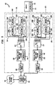
- FIG. 1 is a block diagram of a wireless communication system 102 according to a preferred embodiment of the present invention.
- the wireless communication system 102 covers a geographical area that includes one or more cells 114, each containing one or more sub-cells 116, respectively (the sizes and shapes of the cell 114, and sub-cells 116, are exaggerated in Figure 1 for readability purposes; in practice, each cell 114, generally conforms to the sizes and shapes of the sub-cells 116, respectively, contained therein).
- a cell is an area of radio coverage for a base station over which a predefined system performance level has been established.
- a sub-cell is an area of coverage for a single antenna radiator over which predefined system performance is achieved.
- the wireless communication system 102 provides wireless communication services to mobile units, such as mobile unit 144, which may be located in, or proximate to, one or more of the cells 114.
- each mobile unit 144 represents a receiver/transmitter unit having two antennas (not shown). Dual antennas in each mobile unit 144 provides protection against fading effects that occur over fractions of a wavelength. This is called micro diversity. Each mobile unit 144 determines when to switch among its local antennas based upon previous, short term information about the channel quality.
- This receiver/transmitter unit may also contain adaptive equalization circuitry in order to further help overcome multipath distortion. For example, a weighted sum of the dual antenna outputs can be formed, periodically and made available to the receiver/transmitter. Additional features of the mobile units 144 are discussed below.
- the wireless communication system 102 may be established within a structure, such as a building, or may be established in a combination of structures.
- each cell 114 may correspond to a floor of a building.
- multiple cells, such as cells 114, 126 of Figure 5 may correspond to different areas of the same floor. It should be understood, however, that the wireless communication system 102 of the present invention is equally adapted for use outside of any structure, or for use both inside and outside of one or more structures.
- the wireless communication system 102 includes one or more wireless fixed base (WFB) stations 110, which are also simply called “base stations” herein.
- WFB wireless fixed base
- Each base station 110 is connected to an RF switch 112, respectively.
- Each switch 112 represents any well known RF (radio frequency) multi-position switch, having RF isolation among its positions of 20 dB or better. Additionally, the switch should have a switching speed commensurate with the intra-slot or intra-frame rates in a TDMA/TDD system.
- Each switch 112 is connected to one or more cell antenna units (CAU) 118, respectively.
- the number of cell antenna units 118, respectively connected to each switch 112, may vary from switch to switch, or may be the same for all switches 112, 124, as in Figure 5.
- the switch 112 is connected to four cell antenna units 118.
- Four CAU ⁇ s per base station are considered to be optimum from system performance and cost considerations.
- the cell antenna units 118 serve the dual purpose of extended site coverage from a single base and spatial diversity for avoiding and/or overcoming multipath fading.
- This type of diversity is called macro diversity, to reflect the large relative spacing (compared to a wavelength) between or among the antenna units 118.
- the cell antenna units 118 are placed throughout the region of interest in order to insure complete radio coverage and to overcome multipath fading at certain remote terminal locations. Specifically, one antenna unit 118, is placed in each sub-cell 116, of the cell 114. By having a plurality of cell antenna units 118, it is possible to have less base stations 110, (otherwise, one base station and its associated interface and controller (e.g. 108 and 140) would be required for each sub-cell 116), thereby greatly simplifying system installation and use and minimizing system cost.
- the cell antenna units 118 are connected to their respective base station 110, via preferably coaxial cables that are each less than or equal to approximately 200 feet in length.
- Each antenna unit 118 preferably includes an antenna and a duplexer.
- the duplexer for TDD operation, used to overcome cable losses, preferably includes a pair of RF (radio frequency) switches, a power amplifier for transmission to the various mobiles 144, and a low noise amplifier for reception from the various mobiles 144. DC power for the amplifiers and the control signals for selecting transmit or receive are provided over the coaxial cable.
- Maximum transmitter power from the antennas 118 is preferably limited to 100 mW, peak power. Transmitter power is controlled to minimize adjacent channel interference and to adapt to system coverage needs.
- the switch 112 selectively connects its respective base station 110, to its respective antenna units 118. At any moment of time, each base station 110, is connected to one antenna unit 118, via the switch 112. For example, at any moment of time, base station 110 is connected to one antenna unit 118A via switch 112.
- Each base station 110 is a time division multiple access (TDMA) and/or time division duplex (TDD) radio system.
- TDMA/TDD system makes use of successive time slots to alternately transmit or receive information.
- these transmit and receive time slots are grouped together to define a frame.
- Each base station 110 includes a transceiver (transmitter/receiver combination) that is connected to its respective switch 112.
- Each base station 110 employs well known wireless communication techniques to exchange information with mobile units 144 via the antenna units 118.
- the transmitter and receiver of the base station are alternately connected to the switch and the selected cell antennas synchronously with the downlink and uplink portions of the frame.
- Downlink is a transmission from the base to a mobile.
- Uplink is a transmission from the mobile to the base.
- Digital modulation techniques such as M-ary FSK or M-ary PSK are preferred. All deployed base stations are synchronized with respect to their transmit and receive cycles for lowest intra-system interference.
- a mobile unit 144 communicates with a base station (such as base station 110, for example) via one of the antennas (such as antenna 118A, for example) connected to the base station 110. Prior to communicating with the mobile unit 144 using this antenna 118A, the base station 110 sends an appropriate command to its switch 112 to command the switch 112 to connect it (i.e., the base station 110) to the antenna 118A. The mobile unit 144 listens to transmissions from all of the antennas 118A-118D.
- the mobile unit 144 determines that one of the antennas 118B-118D (that it is not currently using) is “better” than the antenna 118A that it is currently using (for illustrative purposes, assume that antenna 118C is the “better” antenna), then the mobile unit 144 sends a message identifying this "better” antenna 118C to the base station 110. The base station 110 then communicates with the mobile unit 144 using this "better" antenna 118C.
- This operation of the present invention is preferably implemented by a base station controller 140, that is contained in each of the base station 110, in combination with a mobile unit controller 146 that is contained in each mobile unit 144.
- a base station controller 140 that is contained in each of the base station 110
- a mobile unit controller 146 that is contained in each mobile unit 144.
- each mobile unit 114 listens to transmissions from the antennas 118, and determines which is "best". The manner in which this determination is made shall now be discussed.
- the determination of "best” antenna is based on a number of factors which are implementation dependent. For example, the “best” antenna determination can be based on a received signal strength indication(RSSI). Alternatively, the “best” antenna determination can be based on bit error rate (BER) (e.g., by determining the instantaneous error rate from the eye pattern fill-in, referred to as a pseudo-error count.) Or, the "best” antenna determination can be based on any combination of the above. A decision based upon both factors reduces the chances for making a bad antenna selection. Techniques for determining RSSI and BER are well known to persons skilled in the relevant art.
- the determination of "best” antenna may be performed entirely at the mobile units 144, or alternatively performed by both the base station 110, and the mobile units 144. As discussed above, the mobile units 144 communicate their respective selections of "best" antenna to the base station 110.
- the base station 110 is connected to a private branch exchange (PBX) 104 via interface module 108.
- PBX private branch exchange
- the interface module 108 converts the radio signals from the base station 110, into a standard telecommunication interface, such as tip-ring, or any proprietary interface as warranted.
- the structure and operation of the interface module 108 will be apparent to persons skilled in the relevant art.
- the interface module 108 may be integrated with the PBX ⁇ s or the base station 110, or may be distinct from both.
- the interface module 108, base station 110, switch 112, and antennas 118 represent a radio sub-system 101.
- the interface module 120, base station 122, switch 124, and antennas 130 represent another radio sub-system 103.
- the operation of the base station 110 and the mobile units 144 as discussed herein is preferably implemented using a base station controller 140, contained in each base station 110, and a mobile unit controller 146 contained in each mobile unit 144.
- controllers 140, 144 may represent hardware implemented state machines, or may alternatively represent processors operating in accordance with software, or may represent any combination of the above.
- the PBX 104 connects the radio sub-system 101, to a telephone network 106 (which may include local and/or long distance networks). In this manner, mobile units 144 can communicate with fixed and/or mobile units located outside of the cells 114, via the telephone network 106.
- a telephone network 106 which may include local and/or long distance networks.
- mobile units 144 can communicate with fixed and/or mobile units located outside of the cells 114, via the telephone network 106.
- the structure and operation of the PBX 104 and the telephone network 106 will be apparent to persons skilled in the relevant art.
- the first embodiment of the present invention employs the configuration shown in Figure 1 and described above. It also implements both micro and macro diversity to overcome multipath fading effects.
- separate slots in the frame are provided for control and data information. Each control slot is dedicated to a specific antenna.
- the first embodiment of the present invention is best applied to single base station applications.
- data and control signals are transferred between the base station 110, and the mobile units 144 using TDMA (time division multiple access) frames such as that shown in Figure 2A.
- TDMA time division multiple access
- the first embodiment is adapted for use on a per cell basis.
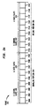
- the frame 202 has a downlink portion 204 and an uplink portion 206.
- the downlink portion 204 includes data and control signals which are transmitted from the base station 110 to the mobile units 144.
- the uplink portion 206 includes data and control signals which are transmitted from the mobile units 144 to the base station 110.
- the downlink portion 204 includes k downlink control slots 208 and n downlink data slots 210.
- the uplink portion 206 includes k uplink control slots 212 and n uplink data slots 214.
- k is equal to the number of antennas 118 connected to the switch 112. Thus, in the example embodiment of Figure 1, k is equal to four.
- n is equal to five in the example frame 202 shown in Figure 2A, although the value of n is implementation dependent.
- control signal refers to a signal that affects system control
- data signal refers to a signal containing user data.
- data slots 210, 214 can carry any type of information, such as voice information, video information, facsimile information, etc.
- data message and “data” and similar phrases are intended herein to refer to all types of user information, such as those just listed.
- Each downlink control slot 208 is associated with one of the antennas 118 connected to the switch 112.
- each uplink control slot 212 is associated with one of the antennas 118 connected to the switch 112.
- the downlink control slot 208 and the uplink control slot 212 associated with a particular antenna occupy the same relative position in the frame 202. For example, if downlink control slot 208C is associated with antenna 118B, then uplink control slot 212C is also associated with antenna 118B.
- no data slots are associated with or pre-assigned to mobiles. These slots are assigned only when calls are set up, and then de-assigned when calls are torn down.
- An active mobile unit is defined herein as being a mobile unit 144 that is currently participating in an established telephone call with the base station 110.
- Any downlink data slot 210 that can be associated with an active mobile unit.
- Any uplink data slot 214 can also be associated with any active mobile unit.
- the downlink data slot 210 and the uplink data slot 214 associated with a particular active mobile unit occupy the same relative position in their respective half frame 204, 206. For example, if downlink data slot 210B is associated with an active mobile unit, then uplink data slot 214B is also associated with the active mobile unit.
- the maximum number of simultaneous telephone calls is a function of the number of downlink data slots 210 (or, equivalently, is a function of the number of uplink data slots 214). In other words, the maximum number of simultaneous telephone calls is equal to n.
- a downlink data slot 210 and an uplink data slot 214 are associated with each active mobile unit.
- any antenna 118A-118D can be associated with (or assigned to) any active mobile unit. These associations may change from one frame to the next frame. However, during any particular frame, an active mobile unit exchanges data with the base station 110 via its assigned antenna and in its assigned downlink and uplink data slots (and, also, at an assigned frequency).
- Flowchart 221 depicts the operational steps that are performed to exchange data and control signals between the base station 110 and an active mobile unit, such as mobile unit 144, during a telephone call that has been previously established (the procedure for establishing telephone calls is discussed below with reference to Figure 2C).
- the operational steps depicted in Flowchart 221 represent the operation of the base station 110 and the active mobile unit 144 during the exchange of a single frame 202, called the "current" frame 202.
- the steps of Flowchart 221 are performed for each frame.
- Flowchart 221 begins with step 220, where control immediately passes to step 222.
- the base station 110 enables the transmission of control messages via the antennas 118A-118D in the downlink control slots 208 of the current frame 202. Specifically, the base station 110 commands the switch 112 to connect the base station 110 to the antenna 118A. Then, the base station 110, transmits a control message via antenna 118A in downlink control slot 208A (it is assumed that downlink control slot 208A is always associated with antenna 118A for illustrative purposes). Then, the base station 110 commands the switch 112 to connect the base station 110 to the antenna 118B.
- the base station 110 transmits a control message via antenna 118B in downlink control slot 208B (it is assumed that downlink control slot 208B is always associated with antenna 118B for illustrative purposes). Similarly, the base station 110 transmits the same control messages via antennas 118C and 118D in downlink control slots 208C and 208D, respectively (it is assumed that downlink control slots 208C and 208D are respectively, always associated with antennas 118C and 118D for illustrative purposes). In this way, the base station, 110, broadcasts the same message through each of its associated antennas, 118.
- a control message is broadcasted in the downlink control slots which contain coded data that identifies the respective antennas.
- the control message transmitted in downlink control slot 208D contains coded data that identifies antenna 118D.
- the control messages may also be longer messages containing, in addition, coded data pertaining to frequency and slot selection, and telephonic terminal state control information, for example.
- mobile units 144 use this information as a handshaking mechanism to establish calls and to adjust to changing communication conditions during the life of previously established active calls.
- slot selection information may be transmitted in response to a new antenna request from an active mobile unit (see step 230, described below).
- the base station 110 enables the transmission of data messages via the appropriate antennas 118A-118D in the appropriate downlink data slots 210 of the current frame 202 (such data messages are received from the telephone network 106 via the PBX 104 and the interface module 108). For example, assume that the base station 110 has a data message that is addressed to the mobile unit 144. Also assume that, for the current frame 202, this mobile unit 144 is assigned to antenna 118C and downlink data slot 210A. Thus, in step 224, the base station 110 commands the switch 112 to connect the base station 110 to antenna 118C. Then, the base station 110 transmits the data message via antenna 118C in downlink data slot 210A. The base station 110 operates in a similar manner to transmit other appropriate data messages in the appropriate downlink data slots 210 via the appropriate antennas 118A-118D for other active mobiles.
- steps 222 and 224 were performed by the base station 110.
- steps 226, 228, 230, and 232 are performed by each active mobile unit. For illustrative purposes, these steps are described with respect to mobile unit 144.
- the mobile unit 144 listens to all of the downlink control slots 208 in the current frame 202 (that is, the mobile unit 144 attempts to receive the control messages contained in all of the control slots 208). The mobile unit 144 determines from these control slots which of the antennas 118A-118D is the "best" antenna. Generally, the "best" antenna represents the antenna 118A-118D with which the mobile unit 144 can communicate with the base station 110 with the highest possible transmission quality. Procedures for determining the "best" antenna are discussed above.
- the mobile unit 114 extracts frequency and/or slot selection information, if any, from the downlink control slot 208 associated with its currently assigned antenna 118. For example, if the mobile unit 114 is assigned to antenna 118A during this portion of the call, then the mobile unit 114 extracts frequency and/or slot selection information, if any, from the downlink control slot 208A. This frequency and/or slot selection information was inserted into the downlink control slot 208A by the base station 110 during step 222 (described above). This frequency and/or slot selection information must be acknowledged and agreed to by the mobile before any changes are made. The changes will take one (or more) frames to complete.
- the mobile unit 144 previously synchronized to, and maintains synchronization with, the timing of the frames transmitted from the base station 110 in any well known manner.
- step 228, the mobile unit 144 receives data in the downlink data slot 210 assigned to it. As discussed above, for the current frame, each active mobile unit is associated with a downlink data slot 210. This association may change from frame to frame (see step 226, described above). During step 228, the mobile unit 144 receives data in the downlink data slot 210 previously assigned to it.
- the mobile unit 144 transmits, if necessary, a request for a new antenna to the base station 110 in the uplink control slot 212 associated with its currently assigned antenna. This is a random process in time. The mobile decides when it needs improved performance as a function of time and its position at that time. For example, suppose that the mobile unit 144 is currently assigned to antenna 118A. Also suppose that in step 226 the mobile unit 144 determined that antenna 118C was the best antenna for its purposes. Accordingly, in step 230, the mobile unit 144 transmits a request for a new antenna (i.e., antenna 118C) to the base station 110 in the uplink control slot associated with the new best antenna 118C.
- a new antenna i.e., antenna 118C
- the mobile unit 144 only transmits such a request if the "best" antenna (determined in step 226) differs from its currently assigned antenna. Note that any request for a new antenna does not affect the operation of the mobile unit 144 during the current frame 202.
- the request for a new antenna may not be clearly transmitted to the base station 110. This may be due to noise or other effects in the communication environment.
- the unsuccessful transmission of a new antenna request does not adversely affect the operation of the system, since the active mobile unit 144 will resend the request (if necessary) in the next frame (or in subsequent frames, until performance is improved.)
- frequency and time slot changes are always negotiated between base and mobile.
- a poling procedure can also be used instead of the random access procedure just described.
- Each mobile is periodically queried to determine its state or need for service. For example, each mobile is asked to respond to the base via the best antenna at a particular time until all mobiles have been poled. During this response, requests for call establishment can be made.
- the delay time for a response (with a 10 ms. frame duration) is less than or equal to 120 ms. Inactive mobiles do not have to be poled continuously, as long as the poling rate is short enough to provide acceptable dial tone delay. Poling insures that a contemplated action is acknowledged before an action is taken.
- step 232 the mobile unit 144 transmits data to the base station 110 in the uplink data slot 214 assigned to the antenna that it is currently monitoring. As discussed above, for the current frame, each active mobile unit is associated with an uplink data slot 214. This association may change from frame to frame and from call to call(reference is made to step 226, described above). During step 232, the mobile unit 144 transmits data in the uplink data slot 212 previously assigned to it. The base station 110 transfers this data to the telephone network 106 via the interface module 108 and the PBX in a well known manner. After performing step 232, performance of flowchart 221 is complete as indicated by step 234.
- Flowchart 240 depicts the operational steps that are performed to establish a new telephone call between a mobile unit, such as mobile unit 144, and a base station, such as base station 110. The steps of Flowchart 240 are performed each time a mobile unit 144 attempts to establish a new telephone call.
- Flowchart 240 begins with step 242, where control immediately passes to step 244.
- a mobile unit such as mobile unit 144, wishing to establish a new telephone call listens to all of the downlink control slots 208 in the current frame 202 (that is, the mobile unit 144 attempts to receive the control messages contained in all of the control slots 208).
- the mobile unit 144 determines which of the antennas 118A-118D is the "best" antenna. Procedures for determining the "best" antenna are discussed above. It is noted that the mobile unit 144 previously synchronized to, and maintains synchronization with, the timing of the frames transmitted from the base station 110 in any well known manner.
- step 246 the mobile unit 144 transmits a request to establish a new telephone call to the base station 110 in the uplink control slot 212A associated with the "best" antenna 118A.
- the request to establish a new telephone call may not be clearly transmitted to the base station 110. This may be due to noise or other effects in the communication environment. This may also be due to conflict between multiple mobile units attempting to transmit during the same uplink control slot 212 (for example, it is possible that two or more mobile units may transmit during the same control slot, having made similar decisions about the best antenna).
- the unsuccessful transmission of a new telephone call request does not adversely affect the operation of the system, since the mobile unit 144 can resend the request (if necessary) in the next frame.
- colloision algorithms that can be employed to mitigate these conflicts.
- the base station 110 Upon receiving the request for a new telephone call from the mobile unit 144, the base station 110 determines whether to accept the request. The base station 110 makes this determination as follows: If the base station 110, has less than n (the # of downlink data slots) active mobiles to which it is transmitting data in active slots, then any one of the unused data slots is assigned to the mobile and the call is accepted.
- n the # of downlink data slots
- the mobile unit can choose an unused uplink control slot to transmit on at a random time (as opposed to when requested to by the base.) Such transmissions are termed random access here. Random access transmissions would be used to initiate communication with the base for the purpose of setting up a voice call, for example.
- the base station 110 accepts the request for a new telephone call, then the base station 110 will communicate that acceptance in the downlink control slot 208 associated with the "best" antenna (determined by the mobile unit 144 in step 244) of the next frame.
- Such acceptance is preferably in the form of a control message containing information that identifies the mobile unit 144 that made the request, and that identifies the frequency, downlink data slot 210, uplink data slot 214, and antenna 118 assigned to the mobile unit 144.
- step 248 the mobile unit 144 reads control information, if any, contained in the downlink control slot 208 associated with the "best" antenna (determined in step 244) of the next frame. As just discussed above, if the base station 110 accepted the request for a new telephone call, then the base station 110 would have communicated that acceptance in this downlink control slot 208. If this downlink control slot contains an acknowledgment of the mobile ⁇ s request (step 249) from base station 110, but does not contain a call acceptance flag (step 250), then the mobile unit 144 determines that the call request was not accepted (step 250), and returns to step 244.
- the mobile unit assumes the request was not received error-free and retransmits in accordance with step 246. To avoid an endless loop condition, the mobile unit can cease the request after m tries.
- step 252 makes any adjustments that are necessary to prepare for the immediately following frame (this "immediately following frame” is the frame which follows the "next frame”; recall that the "next frame” followed the "current frame), such as adjusting for the frequency and the data slots assigned to the mobile unit 144 (see step 248). Operation of the flowchart 240 is complete after the completion of step 252, as indicated by step 254. Once the call is established, operation of the base station 110 and the mobile unit 144 is as shown in Figure 2B, described above.
- data and control signals are transferred between the base station 110, and the mobile units 144 using TDMA (time division multiple access) frames such as that shown in Figure 3A.
- TDMA time division multiple access
- the physical structure of the second embodiment of the present invention is the same as that shown in Figure 1 and described in Section 2. above.
- the second embodiment differs from the first embodiment in that the control and data information are now combined into specific fields of one slot.
- the number of these combined function slots in a frame is implementation dependent, but there is always one slot for each active call or other activity in the system.
- the second embodiment also employs both macro and micro diversity.
- the frame 302 has a downlink portion 304 and an uplink portion 306.
- the downlink portion 304 includes data and control signals which are transmitted from the base station 110 to the mobile units 144.
- the uplink portion 306 includes data and control signals which are transmitted from the mobile units 144 to the base station 110.
- the downlink portion 304 includes x downlink, combined control/data slots 308 and are herein after referred to simply as slots.
- the uplink portion 306 includes x uplink slots 312.
- the quantity x is equal to 8 in the example frame 302 shown in Figure 3A, although the value of x is implementation dependent.
- a downlink slot 308 is associated with each mobile unit that is on an active call.
- Each uplink slot 312 is also associated with an active mobile unit.
- the downlink slot 308 and the uplink slot 312 associated with a particular active mobile unit occupy the same relative position in the frame 302. For example, if downlink slot 308B is associated with an active mobile unit, then uplink slot 312B is also associated with the active mobile unit.
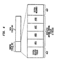
- FIG 4 illustrates the format of the downlink and uplink slots 308, 312.
- Each downlink and uplink slot 308, 312 includes a control field 402 and a single data field 404.
- the control field is broken down further into several sub-fields, as shown in Figure 4.
- the field 402E might contain control information such as guard bits, preamble bits, synchronization bits and check bits.
- subfield 402F might contain system messages associated with usable frequencies, usable uplink slots, terminal status, update control messages and check bits.
- the fields 402A through D are referred to as z fields. Their number is equal to the number of antennas 118 connected to the switch 112 (thus, z is equal to 4, in this example).
- Each z field 402A-D is associated with one of the antennas 118 connected to the switch 112.
- the z fields are pertinent to the present invention. Their specific location is not important as long as they are present and their fixed position is known so that they can be monitored.
- the size of the z fields is at least two bits. Longer bit streams can be used and the patterns of the bits can be chosen to meet performance and cost goals of the system. The longer the pattern, in general, the more robust the detection of it, but the greater the cost for the circuitry/algorithms involved.
- the mobile can make a decision based upon the RSSI in each z field, or the number of errors in each z field, or both.
- control field 402 is meant to illustrate the kinds of information that a knowledgeable system designer might place in such fields.
- the maximum number of allowable telephone calls is a function of the number of downlink slots 308 (or, equivalently, is a function of the number of uplink slots 312). In other words, the maximum number of allowable telephone calls is a function of x. This represents one difference between the first and second embodiments of the present invention.
- the capacity for active telephone calls is greater in the second embodiment, since in the second embodiment, each slot contains both control and data information, while in the first embodiment, only some of the slots carry data information.
- a downlink slot 308 and an uplink slot 312 are associated with each active mobile unit.
- an antenna 118A-118D is associated with (or assigned to) each active mobile unit. These associations may change from one frame to the next frame. However, during any particular frame, an active mobile unit exchanges data with the base station 110 via its assigned antenna and in its assigned downlink and uplink slots 308, 312 (and, also, at an assigned frequency).
- Flowchart 320 depicts the operational steps that are performed to exchange data and control signals between the base station 110 and an active mobile unit, such as mobile unit 144, during a telephone call that has been previously established (the procedure for establishing telephone calls according to the second embodiment is discussed below with reference to Figure 3C).
- the operational steps depicted in Flowchart 320 represent the operation of the base station 110 and the active mobile unit 144 during the exchange of a single frame 302, called the "current" frame 302.
- the steps of Flowchart 320 are performed for each frame.
- Flowchart 320 begins with step 322, where control immediately passes to step 324.
- the base station 110 enables the transmission of the control field 402 of the downlink slot 308A of the current frame 302 via the antennas 118A-118D in the following manner.
- the antenna 118A is assigned to the mobile unit 144 during the current frame 302.
- the base station 110 commands the switch 112 to connect the base station 110 to the antenna 118A.
- the base station 110 commands the switch 112 to connect the base station 110 to the antenna assigned to a z-field during that z-field's portion of the slot. For example, if z-field 402B was assigned to antenna 118B then the base station 110 commands the switch 112 to connect the base station 110 to antenna 118B during z-field 402B.
- the base station 110 enables the transmission of a data message intended for mobile unit 144 via the antenna unit associated with the mobile unit (118A). This data message was received from the telephone network 106 via the PBX 104 and the interface module 108. This data message is transmitted in data field 404 of downlink slot 308A of the current frame 302. In step 326, the base station 110 commands the switch 112 to connect base station 110 to antenna 118A during the transmission of data field 404 of downlink slot 302A of the current frame 302.
- the mobile unit 144 listens to its assigned downlink slot 308A including all contained control and data fields. From the reception of the z-fields, the mobile unit 144 determines which of the antennas 118A-118D is the "best" antenna. Procedures for determining the "best" antenna are discussed above. Also during step 330, the mobile unit extracts system information inserted into the system message field 402F of downlink slot 308A by the base station 110 during step 324 (described above). Such information may affect the operation of the base station and mobile unit 144 during the next frame (that is, the frame that immediately follows the current frame) as described above.
- step 332 the mobile unit 144 receives data from the data slot 404 in its downlink slot 308A of the current frame 302.
- steps 330 and 332 are performed by all of the active mobile units with regard to their respective downlink slots 308. After such performance of steps 330 and 332, step 334 is performed.
- the mobile unit 144 transmits, if necessary, a request for a new antenna to the base station 110.
- This new antenna request is transmitted in the uplink slot 312A associated with the mobile unit 144. More specifically, this new antenna request is transmitted in the z field 402A-D (in the uplink slot 312A) that is associated with the antenna 118 assigned to the mobile unit 144. For example, suppose that the mobile unit 144 is currently assigned to antenna 118B. Also suppose that in step 330 the mobile unit 144 determined that antenna 118C was the "best" antenna for its purposes.
- the mobile unit 144 transmits a request for a new antenna (i.e., antenna 118C) to the base station 110 in the z field 402B (in the uplink slot 312A) that is associated with the antenna 118C.
- a new antenna i.e., antenna 118C
- the mobile unit 144 is always transmitting its "best" antenna assessment in the appropriate z field (determined in step 330.) Note that any request for a new antenna does not affect the operation of the mobile unit 144 during the current frame 302.
- the request for a new antenna may not be clearly transmitted to the base station 110. This may be due to noise or other effects in the communication environment.
- the unsuccessful transmission of a new antenna request does not adversely affect the operation of the system, since the active mobile unit 144 continuously sends its assessment of the best antenna in all succeeding frames.
- the base station 110 Upon noting a change in the z fields from the mobile unit 144, the base station 110 determines which antenna to use for that mobile in the next downlink frame. The manner in which the base station 110 makes this determination is described above.
- step 336 the mobile unit 144 transmits data to the base station 110 in the data field 404 of its uplink slot 312A in the current frame.
- the base station 110 transfers this data to the telephone network 106 via the interface module 108 and the PBX in a well known manner.
- performance of flowchart 320 is complete as indicated by step 338.
- Flowchart 340 depicts the operational steps that are performed to establish a new telephone call between a mobile unit, such as mobile unit 144, and a base station, such as base station 110, according to the second embodiment.
- the steps of Flowchart 340 are performed each time a mobile unit 144 attempts to establish a new telephone call.
- Flowchart 340 begins with step 342, where control immediately passes to step 344.
- the base station 110 is required to transmit system information in at least one downlink slot of every frame.
- this required slot is slot 308E, for example.
- a mobile unit such as mobile unit 144, wishing to establish a new telephone call, synchronizes to a downlink slot (such as downlink slot 308E) in the current frame 302.
- the mobile unit 144 recognizes from its contents, that slot 308E is a general purpose, informational slot transmitted by the system. Slots of this type are called beacon slots.
- a beacon slot contains control information of the type described above in the discussion of the control fields 402.
- a beacon slot does not necessarily have an information field associated with it, but it could have one, if the traffic load demands it.
- any active slot can be considered to be a beacon slot for the system.
- slot 308E could be a beacon slot containing system information such as the base station ⁇ s good frequency list at that moment and the slots available for new calls in the next frame or mobile responses in the uplink of the current frame.
- the base station continuously monitors all uplink slots in every frame.
- the Mobile unit 144 wanting service, syncs to beacon slot 308E and reads the system information.
- the mobile unit 144 listens to all of the control fields 402 in the identified downlink slot 308E.
- the mobile unit 144 determines which of the antennas 118A-118D is the "best" antenna following the procedures for determining the "best” antenna discussed above. It is noted that the mobile unit 144 previously synchronized to, and maintains synchronization with, the timing of the frames transmitted from the base station 110 in any well known manner.
- the Mobile unit 144 compares its own good frequency list to the base station list and selects a mutually acceptable frequency. There may be a delay involved if the chosen frequency is low on a list of sequentially used frequencies acceptable to the base station, since the base station may take several frames per frequency to pass through its entire list. From the available uplink slots, the Mobile 144, also selects its uplink slot. For example, the chosen slot could be slot 312E.
- the mobile unit 144 identifies an uplink slot, such as uplink slot 312E (the procedure for identifying available slots is described above), and transmits a request to establish a new telephone call to the base station 110 in the identified uplink slot 312E. Specifically, this new telephone call request is transmitted in the control slot field (of the uplink slot 312E). The best antenna information is also sent in the appropriate z field of the selected uplink slot. For example, suppose that in step 346 the mobile unit 144 determined that the "best" antenna was antenna 118A. Accordingly, in step 350, the mobile unit 144 transmits a request to establish a new telephone call to the base station 110 in control field 402 in uplink slot 312E.
- uplink slot 312E the procedure for identifying available slots is described above
- the request to establish a new telephone call may not be clearly transmitted to the base station 110. This may be due to noise or other effects in the communication environment. This may also be due to conflict between multiple mobile units attempting to transmit during the same slot 312E, for example.
- the unsuccessful transmission of a new telephone call request does not adversely affect the operation of the system, since the mobile unit 144 can resend the request (if necessary) in the next frame.
- the base station 110 Upon receiving the request for a new telephone call from the mobile unit 144, the base station 110 determines whether to accept the request. The base station 110 makes this determination as described above. If the base station 110 accepts the request for a new telephone call, then the base station 110 will preferably communicate that acceptance in the downlink slot 308E (of the next frame) selected in step 348. Such acceptance is preferably in the form of a control message in field 402F containing information that identifies at least the mobile unit 144 who made the request, and that identifies the frequency, downlink 308, uplink slot 312, and an antenna 118 control message in the appropriate z field.
- step 352 the mobile unit 144 determines whether the new call request was accepted by monitoring the downlink slot 308 (of the next frame) which it selected in step 348. The absence of control data directed to it indicates that the new call request was not accepted. In this case, control returns to step 346.
- step 352 If the new call request was accepted (as determined in step 352), then the mobile unit 144 in step 356 transmits data in its assigned uplink slot 312. Operation of the flowchart 340 is complete after the completion of step 356, as indicated by step 358. Once the call is established, operation of the base station 110 and the mobile unit 144 is as shown in Figure 3B, described above.
- the random access mode of communication requires that the antennas associated with the base be connected simultaneously for the period of time associated with each of the unassigned uplink slots.
- This mode of operation of the CAU switch 112 is termed BIG EAR, since all CAUs connected to the base station via the switch 112, are listening at the same time.
- the WFB 110 will be able to receive the mobile unit ⁇ s uplink transmission without having to know where the mobile unit is.
- the WFB 110 would utilize the assigned antenna for its transmitted response back to the mobile, acknowledging assignment of the chosen slot for communication with the mobile unit, as described above. Until indicated otherwise, the assigned antenna would be used by the WFB 110, for both reception and transmission of the assigned slot, unless one of the z fields changes as described above.
- the frame structure described for the second embodiment of the invention has been used by other wireless systems in the past (e.g., Digital European Cordless Telecommunication (DECT) system) to span many cells.
- DECT Digital European Cordless Telecommunication
- the operation of these and like systems allows for the user data service to be provided on an uninterrupted basis as an active mobile unit is moved from one cell to the next, e.g., from cell 114 to cell 126.
- Such a capability known as hand-off, is made possible through hardware additions and control protocol additions to the single cell system described above. Such additions are well known to system designers and persons skilled in the art of wireless systems.
- PBX 104 For example, a feature of the PBX 104, needs to be added to provide for connectivity changes from one WFB 110, to a second WFB 122, during a voice conversation.
- certain control codes must be added to the control fields in both the stationary end (WFBs 110,122, Interface/controller 108,140 and 120,142, or PBX 104) and mobile unit 144, and its controller 146, to accomplish the tasks and communication necessary for hand-off.
- Hand-off is a process which, because of its high impact on shared hardware and control resource utilization, should be used sparingly. This is allowed for by choosing hand-off criteria that allow for switching between cells only when the general performance of one cell has degraded to the extent that hand-off to another cell (if better) is warranted. In general, this results in two characteristics we wish to discuss further: 1) the number of hand-offs during the time a mobile unit is active (e.g., on a call) is on the order of one or two per minute; and 2), the time over which the transition occurs (from recognition that hand-off is needed to completion of hand-off) occurs over many frames (e.g., 40 to 50).
- the metrics used to determine when hand-off is needed are those that tend not to include the short term variations in signal quality which the present invention is able to combat.
- the invention might use measures of BER variations over two frames to determine best antenna for a subsequent frame and subsequently, antenna switching can occur on every frame.
- hand-off criteria are averaged over many frames (20 to 30) and the interval between hand-offs would occur on the order of seconds to minutes.
- the operation of the present invention serves to provide better service within a cell by combating short term impairment occurrences.
- Hand-off combats long term impairments due to inter-cell movement. In this way, the operation of the present invention does not hinder the operation necessary for inter-cell hand-off, and, in fact, uses it for multi cell operation, as well.
- the control mechanism described in the second embodiment of the present invention provides for a separation of antenna control and other system control functions. Specifically, the location and use of the antenna fields in an active slot in no way impedes the use of the other fields used for system control functions such as for hand-off communication.
- the present invention may be active in such systems that provide for multi-cell operation and provide both increased base station coverage and macro diversity in a form transparent to the multi-cell operation.
Landscapes
- Engineering & Computer Science (AREA)
- Computer Networks & Wireless Communication (AREA)
- Signal Processing (AREA)
- Mobile Radio Communication Systems (AREA)
- Radio Transmission System (AREA)
Claims (14)
- Procédé pour obtenir une couverture augmentée et une macrodiversité accrue à partir d'un poste de base unique dans un système de communication radio ou sans fil ayant un poste de base couplé à N antennes, caractérisé par les étapes qui consistent à :(1) transmettre à partir du poste de base N messages de commande, chacun par l'intermédiaire d'une des antennes ;(2) transmettre un message de données adressé à une unité mobile par l'intermédiaire de l'une particulière des antennes précédemment affectée à l'unité mobile pour la durée d'un appel actif ;(3) recevoir dans ladite unité mobile les messages de commande et le message de données ;(4) analyser dans l'unité mobile les messages de commande pour identifier à partir des antennes une antenne la meilleure ;(5) transmettre à partir de l'unité mobile vers le poste de base une requête de nouvelle antenne identifiant ladite antenne la meilleure dans un créneau de commande en liaison montante d'une trame, le créneau de commande de liaison montante étant associé à ladite une antenne particulière parmi les antennes ; et(6) utiliser en réponse à la requête de nouvelle antenne l'antenne la meilleure pour transmettre à partir du poste de base un ou plusieurs messages de données suivants adressés à l'unité mobile.
- Procédé suivant la revendication 1, dans lequel l'étape (1) comporte les étapes qui consistent à :effectuer les étapes (a) et (b) pour chacune des antennes.(a) connecter le poste de base à l'une des antennes ;(b) transmettre à partir du poste de base un message de commande par l'intermédiaire de ladite une des antennes dans un créneau de commande en liaison descendante de la trame, le créneau de commande en liaison descendante étant associé à ladite une des antennes ;
- Procédé suivant la revendication 1, dans lequel l'étape (2) comporte l'étape qui consiste à :transmettre le message de données par l'intermédiaire de ladite une particulière des antennes dans un créneau de données de liaison descendante précédemment affecté à l'unité mobile.
- Procédé suivant la revendication 1, comportant en outre les étapes suivantes qui sont effectuées après l'étape (4) :déterminer si l'antenne la meilleure est égale à ladite une antenne particulière précédemment affectée à l'unité mobile ; etse passer de l'étape (5) si l'antenne la meilleure est égale à ladite une particulière des antennes précédemment affectée à l'unité mobile.
- Procédé suivant la revendication 1, comportant en outre les étapes qui consistent à :(7) recevoir dans une deuxième unité mobile souhaitant établir un nouvel appel téléphonique lesdits messages de commande ;(8) analyser dans la deuxième unité mobile les messages de commande pour identifier parmi les antennes une antenne la meilleure par rapport à la deuxième unité mobile ; et(9) transmettre à partir de la deuxième unité mobile au poste de base une nouvelle requête d'appel téléphonique identifiant l'antenne la meilleure par rapport à la deuxième unité mobile dans un deuxième créneau de commande de liaison montante de la trame, le deuxième créneau de commande de liaison montante étant associé à ladite meilleure antenne par rapport à la deuxième unité mobile.
- Procédé suivant la revendication 1, comportant les étapes qui consistent à :(1) transmettre à partir du poste de base N messages de commande dans N champs de commande d'un créneau de données/commande de liaison descendante qui est associé à une unité mobile pour la durée d'un appel actif, chacun des messages de commande étant transmis par l'intermédiaire de l'une des antennes ;(2) transmettre un message de données adressé à l'unité mobile dans un champ de données du créneau de données/commande de liaison descendante, le message de données étant transmis par l'intermédiaire d'une particulière des antennes précédemment affectées à l'unité mobile ;(3) recevoir dans l'unité mobile les messages de commande et le message de données ;(4) analyser dans l'unité mobile les messages de commande pour identifier parmi les antennes une antenne la meilleure ;(5) transmettre à partir de l'unité mobile au poste de base une requête de nouvelle antenne identifiant l'antenne la meilleure dans un champ de commande d'un créneau de données/de commande de liaison montante de la trame, le créneau de données/commande de liaison montante étant associé à l'unité mobile pour la durée d'un appel actif, le champ de commande du créneau de données/de commande de liaison montante étant associé à ladite une particulière des antennes ; et(6) utiliser en réponse à la requête de nouvelle antenne l'antenne la meilleure pour transmettre à partir du poste de base un ou plusieurs messages de données suivants adressés à l'unité mobile.
- Procédé suivant la revendication 6, dans lequel l'étape (1) comporte les étapes qui consistent à :effectuer les étapes (a) et (b) pour chacune des antennes.(a) connecter le poste de base à l'une des antennes ;(b) transmettre à partir du poste de base un message de commande par l'intermédiaire de ladite une des antennes dans l'un des champs de commande, du créneau de données/commande de liaison descendante, associé à l'une des antennes ;
- Procédé suivant la revendication 6, comportant en outre les étapes suivantes qui sont effectuées après l'étape (4) :déterminer si l'antenne la meilleure est égale à ladite une particulière des antennes précédemment affectées à l'unité mobile ; etse passer de l'étape (5) si l'antenne la meilleure est égale à ladite une particulière des antennes précédemment affectées à l'unité mobile.
- Procédé suivant la revendication 6, comportant en outre les étapes qui consistent à :(7) transmettre à partir du poste de base des messages de commande dans des champs de commande d'un créneau en liaison descendante, appelé un créneau balise, de la trame, chacun des messages de commande incluant des informations identifiant des créneaux et des fréquences disponibles à l'utilisation dans de nouveaux appels téléphoniques ; et incluant des informations transmises de chaque antenne à leur tour ;(8) recevoir dans une deuxième unité mobile souhaitant établir un nouvel appel téléphonique les messages de commande de balise ;(9) analyser dans la deuxième unité mobile les messages de commande pour identifier parmi les antennes une antenne la meilleure par rapport à la deuxième unité mobile ;(10) sélectionner l'un des créneaux disponibles ;(11) transmettre à partir de la deuxième unité mobile au poste de base une requête de nouvel appel téléphonique identifiant le créneau disponible sélectionné et l'antenne la meilleure par rapport à la deuxième unité mobile dans un champ de commande d'un créneau en liaison montante de la trame.
- Sous-système radio d'un système de communication sans fil ou radio, comportant :le poste de base étant caractérisé par :un poste (110) de base ;N antennes (118) chacune positionnée dans une sous-cellule (116) d'une cellule ;un commutateur (112) connecté au poste (110) de base et aux antennes (118), pour connecter sélectivement le poste (110) de base aux antennes (118) ; etune unité (144) mobile ;des moyens (140) destinés à transmettre N messages de commande, chacun par l'intermédiaire d'une antenne respective des antennes ; etdes moyens (140) destinés à transmettre un message de données adressé à l'unité mobile par l'intermédiaire d'une antenne particulière parmi les antennes précédemment affectées à l'unité mobile, l'unité mobile comportant :des moyens (144, 146) destinés à recevoir les messages de commande et le message de données ;des moyens (144, 146) destinés à analyser les messages de commande pour identifier à partir des antennes une antenne la meilleure ; etdes moyens (144, 146) destinés à transmettre au poste de base une requête de nouvelle antenne identifiant l'antenne la meilleure.
- Sous-système radio suivant la revendication 10, dans lequel le poste de base comporte en outre :des moyens (140) destinés à utiliser en réponse à la requête de nouvelle antenne l'antenne la meilleure pour transmettre un ou plusieurs messages de données suivants adressés à l'unité (144) mobile.
- Sous-système radio suivant la revendication 10, comportant en outre une deuxième unité (144) mobile souhaitant établir un nouvel appel téléphonique, la deuxième unité (144) mobile comportantdes moyens (144, 146) destinés à recevoir les messages de commande ;des moyens (144, 146) destinés à analyser les messages de commande pour identifier à partir des antennes (118) une antenne la meilleure par rapport à la deuxième unité (144) mobile ; etdes moyens destinés à transmettre au poste (110) de base une requête de nouvel appel téléphonique identifiant l'antenne la meilleure par rapport à la deuxième unité (144) mobile.
- Sous-système radio suivant la revendication 10, dans lequel le poste (110) de base comporte en outre :des moyens (140) destinés à transmettre N messages de commande pilotes dans N champs de commande d'un créneau balise en liaison descendante, chacun des messages de commande balise incluant des informations identifiant des créneaux disponibles à l'utilisation dans de nouveaux appels téléphoniques.
- Sous-système radio suivant la revendication 13, comportant en outre une deuxième unité mobile souhaitant établir un nouvel appel téléphonique, la deuxième unité (144) mobile comportant :des moyens (146) destinés à recevoir les messages de commande balise ;des moyens (146) destinés à analyser les messages de commande balise pour identifier parmi les antennes une antenne la meilleure par rapport à la deuxième unité mobile ;des moyens (146) destinés à sélectionner l'un des créneaux temporels disponibles et des canaux de fréquence disponibles ;des moyens (144, 146) destinés à transmettre au poste de base une requête de nouvel appel téléphonique identifiant le créneau disponible sélectionné et l'antenne la meilleure par rapport à la deuxième unité (144) mobile dans un créneau de commande d'un créneau en liaison montante.
Applications Claiming Priority (2)
| Application Number | Priority Date | Filing Date | Title |
|---|---|---|---|
| US08/304,319 US5628052A (en) | 1994-09-12 | 1994-09-12 | Wireless communication system using distributed switched antennas |
| US304319 | 1994-09-12 |
Publications (2)
| Publication Number | Publication Date |
|---|---|
| EP0702462A1 EP0702462A1 (fr) | 1996-03-20 |
| EP0702462B1 true EP0702462B1 (fr) | 2002-10-16 |
Family
ID=23176015
Family Applications (1)
| Application Number | Title | Priority Date | Filing Date |
|---|---|---|---|
| EP95306066A Expired - Lifetime EP0702462B1 (fr) | 1994-09-12 | 1995-08-30 | Système de communication sans fil utilisant des antennes commutées et distribuées |
Country Status (5)
| Country | Link |
|---|---|
| US (1) | US5628052A (fr) |
| EP (1) | EP0702462B1 (fr) |
| JP (1) | JPH0888599A (fr) |
| CA (1) | CA2154303C (fr) |
| DE (1) | DE69528561T2 (fr) |
Cited By (2)
| Publication number | Priority date | Publication date | Assignee | Title |
|---|---|---|---|---|
| US7359971B2 (en) | 1998-07-10 | 2008-04-15 | Van Drebbel Mariner Llc | Use of priority-based scheduling for the optimization of latency and jitter sensitive IP flows in a wireless point to multi-point transmission system |
| US8761834B2 (en) | 2008-12-31 | 2014-06-24 | Motorola Mobility Llc | Method and apparatus for antenna selection and power control in a multiple input multiple output wireless communication system |
Families Citing this family (94)
| Publication number | Priority date | Publication date | Assignee | Title |
|---|---|---|---|---|
| US6895253B1 (en) * | 1995-03-14 | 2005-05-17 | Lucent Technologies Inc. | Wireless indoor communications using antenna arrays |
| JP2751869B2 (ja) * | 1995-04-28 | 1998-05-18 | 日本電気株式会社 | 送信ダイバシティ方式 |
| DE69629633T2 (de) * | 1995-07-19 | 2004-06-17 | Nec Corp. | Vielfaltnachrichtenübertragungssystem mit Kodemultiplexvielfachzugriff |
| US6212387B1 (en) * | 1995-10-18 | 2001-04-03 | Sc-Wireless Inc. | Method and apparatus for collector arrays of directional antennas co-located with zone managers in wireless communications systems |
| US6137784A (en) * | 1995-10-18 | 2000-10-24 | Sc-Wireless Inc. | Method and apparatus for wireless communication employing control for confidence metric bandwidth reduction |
| US6192038B1 (en) * | 1995-10-18 | 2001-02-20 | Mdiversity Inc. | Method and apparatus for wireless communication employing aggregation for digital signals |
| US6131034A (en) * | 1995-10-18 | 2000-10-10 | Sc-Wireless Inc | Method and apparatus for collector arrays in wireless communications systems |
| JP2947157B2 (ja) * | 1996-03-07 | 1999-09-13 | 日本電気株式会社 | 送信空間ダイバーシティ制御方法及び送信空間ダイバーシティ装置 |
| JPH09271070A (ja) * | 1996-03-29 | 1997-10-14 | Matsushita Electric Ind Co Ltd | ディジタル移動体通信装置 |
| EP0807989B1 (fr) * | 1996-05-17 | 2001-06-27 | Motorola Ltd | Procédé et appareil de pondération d'une voie de transmission |
| US5995492A (en) * | 1996-06-28 | 1999-11-30 | Ctp Systems, Ltd. | Method and apparatus for using duality to remotely communicate |
| US5805575A (en) * | 1996-08-19 | 1998-09-08 | Motorola, Inc. | Apparatus and method for providing a beacon signal in a wireless communication system |
| US5959999A (en) * | 1996-09-20 | 1999-09-28 | Linkabit Wireless, Inc. | Providing control-function data in communication-data channel of a full-mesh satellite communication network by dynamic time-slot assignment in TDMA-frame communication channel |
| GB2317786B (en) * | 1996-09-25 | 2001-05-30 | Motorola Ltd | Communication system with a deamformed control channel and method of system control |
| GB2318482B (en) * | 1996-10-16 | 2001-06-13 | Ico Services Ltd | Communication system |
| CA2188845A1 (fr) * | 1996-10-25 | 1998-04-25 | Stephen Ross Todd | Sélection d'une antenne fonctionnant en diversité |
| US5864764A (en) * | 1996-11-25 | 1999-01-26 | Motorola, Inc. | Infrastructure transceiver and method for configuration based on location information |
| US6385464B1 (en) * | 1996-11-26 | 2002-05-07 | Sanyo Electric Co., Ltd. | Base station for mobile communication system |
| US6292516B1 (en) * | 1997-02-13 | 2001-09-18 | Cisco Technology, Inc. | Communication system using packets stuffed with test words for evaluating data reception characteristics while providing increased data throughput |
| FI107506B (fi) * | 1997-02-27 | 2001-08-15 | Nokia Networks Oy | Menetelmä kanavanvaihdon tekemiseksi solukkoradiojärjestelmässä |
| FI107688B (fi) | 1997-02-27 | 2001-09-14 | Nokia Networks Oy | Menetelmä dynaamisen kanavienjaon toteuttamiseksi solukkoradiojärjestelmässä |
| CA2226102C (fr) * | 1997-03-12 | 2002-06-11 | Denso Corporation | Technique de teleappel pour systemes de communications personnelles et dispositif associe |
| US6104930A (en) * | 1997-05-02 | 2000-08-15 | Nortel Networks Corporation | Floating transceiver assignment for cellular radio |
| FI105876B (fi) * | 1997-06-18 | 2000-10-13 | Nokia Networks Oy | Naapurialisolujen määritys tukiasemassa |
| US6349094B1 (en) * | 1997-07-03 | 2002-02-19 | Mdiversity Inc. | Method and apparatus for wireless communications employing control for broadcast transmission |
| DE19733857C1 (de) * | 1997-08-05 | 1999-02-18 | Nokia Mobile Phones Ltd | Zellulares Telekommunikationssystem |
| IL121548A0 (en) * | 1997-08-14 | 1998-02-08 | Telescicom Ltd | Wireless telecommunications system |
| IL121549A (en) * | 1997-08-14 | 2000-09-28 | Telescicom Ltd | Dynamic wireless telecommunications system |
| US6131016A (en) * | 1997-08-27 | 2000-10-10 | At&T Corp | Method and apparatus for enhancing communication reception at a wireless communication terminal |
| US6055230A (en) * | 1997-09-05 | 2000-04-25 | Metawave Communications Corporation | Embedded digital beam switching |
| US6801788B1 (en) * | 1997-09-09 | 2004-10-05 | Samsung Electronics Co., Ltd. | Distributed architecture for a base station transceiver subsystem having a radio unit that is remotely programmable |
| US6771627B1 (en) | 1997-10-15 | 2004-08-03 | Ico Services Limited | Method of operating a mobile station for diversity communication |
| SE511365C2 (sv) * | 1998-01-23 | 1999-09-20 | Ericsson Telefon Ab L M | Antennomkopplingsdiversitet |
| US6728540B1 (en) | 1998-03-09 | 2004-04-27 | Avaya Technology Corp. | Assisted handover in a wireless communication system |
| US6351463B1 (en) | 1998-04-06 | 2002-02-26 | Avaya Technology Corp. | Method and apparatus for transmitting a synchronization beacon in a wireless communication network |
| FI981377A7 (fi) * | 1998-04-24 | 1999-10-25 | Nokia Networks Oy | Lähetysantennidiversiteetti |
| FI981518L (fi) * | 1998-07-01 | 2000-01-02 | Nokia Mobile Phones Ltd | Tiedonsiirtomenetelmä ja radiojärjestelmä |
| US6373832B1 (en) * | 1998-07-02 | 2002-04-16 | Lucent Technologies Inc. | Code division multiple access communication with enhanced multipath diversity |
| US6452915B1 (en) | 1998-07-10 | 2002-09-17 | Malibu Networks, Inc. | IP-flow classification in a wireless point to multi-point (PTMP) transmission system |
| US6609012B1 (en) * | 1998-08-24 | 2003-08-19 | Telefonaktiebolaget Lm Ericsson | Mobile terminal initiated and assisted antenna selection |
| US6405018B1 (en) * | 1999-01-11 | 2002-06-11 | Metawave Communications Corporation | Indoor distributed microcell |
| AU5920000A (en) * | 1999-07-09 | 2001-02-13 | Malibu Networks, Inc. | Method for transmission control protocol (tcp) rate control with link-layer acknowledgements in a wireless point to multi-point (ptmp) transmission system |
| JP2001078261A (ja) * | 1999-09-06 | 2001-03-23 | Tsumura Sogo Kenkyusho:Kk | 電話規制システムおよびこのシステムで用いられる携帯電話端末装置 |
| US6594475B1 (en) | 1999-09-09 | 2003-07-15 | International Business Machines Corporation | Mobile battery discharge minimization in indoor wireless networks by antenna switching |
| FI19991940A7 (fi) * | 1999-09-10 | 2001-03-11 | Nokia Corp | Lähetysdiversiteetti |
| JP2001128215A (ja) * | 1999-10-29 | 2001-05-11 | Matsushita Electric Ind Co Ltd | Tdma−tdd方式送受信装置および送受信方法 |
| AU2756201A (en) | 2000-01-07 | 2001-07-16 | Mdiversity, Inc. | Dynamic channel allocation in multiple-access communication systems |
| US7142520B1 (en) * | 2000-06-16 | 2006-11-28 | Nokia Mobile Phones Ltd. | Method and apparatus for mobile internet protocol regional paging |
| US6898441B1 (en) * | 2000-09-12 | 2005-05-24 | Lucent Technologies Inc. | Communication system having a flexible transmit configuration |
| FI114682B (fi) * | 2000-10-13 | 2004-11-30 | Nokia Corp | Menetelmä ja järjestely nopean signaloinnin toteuttamiseksi asymmetrisessä tietoliikenneyhteydessä |
| US6751480B2 (en) * | 2000-12-01 | 2004-06-15 | Lucent Technologies Inc. | Method for simultaneously conveying information to multiple mobiles with multiple antennas |
| CN1312955C (zh) * | 2000-12-11 | 2007-04-25 | 夏普株式会社 | 无线通信系统 |
| US20020128026A1 (en) * | 2001-01-15 | 2002-09-12 | Derryberry Roy Thomas | System and method for channel prediction for closed loop diversity |
| JP2004529555A (ja) * | 2001-03-30 | 2004-09-24 | 松下電器産業株式会社 | 合成選択時間切り替え送信ダイバーシチ(ststd)方法およびシステム |
| US6662024B2 (en) * | 2001-05-16 | 2003-12-09 | Qualcomm Incorporated | Method and apparatus for allocating downlink resources in a multiple-input multiple-output (MIMO) communication system |
| JP3540782B2 (ja) * | 2001-08-06 | 2004-07-07 | 三洋電機株式会社 | 無線基地装置、無線端末装置、移動体通信システム、および受信動作制御プログラム |
| US7224685B2 (en) * | 2001-09-13 | 2007-05-29 | Ipr Licensing, Inc. | Method of detection of signals using an adaptive antenna in a peer-to-peer network |
| US7327798B2 (en) * | 2001-10-19 | 2008-02-05 | Lg Electronics Inc. | Method and apparatus for transmitting/receiving signals in multiple-input multiple-output communication system provided with plurality of antenna elements |
| US7116944B2 (en) * | 2002-02-07 | 2006-10-03 | Lucent Technologies Inc. | Method and apparatus for feedback error detection in a wireless communications systems |
| US7499709B2 (en) * | 2002-02-07 | 2009-03-03 | Alcatel-Lucent Usa Inc. | Method and apparatus for closed loop transmit diversity in a wireless communications system |
| US7099695B1 (en) * | 2002-05-24 | 2006-08-29 | Sprint Spectrum L.P. | Method and system of selecting antennas and equipment for use within a wireless communication system |
| US20040204105A1 (en) * | 2002-05-24 | 2004-10-14 | Ying-Chang Liang | Method and apparatus for a base station with multiple distributed antennas to communicate with mobile stations |
| US6987952B2 (en) * | 2002-09-30 | 2006-01-17 | Nokia Corporation | Apparatus, and associated method, for effectuating transmit diversity in a communication system |
| US7406295B1 (en) | 2003-09-10 | 2008-07-29 | Sprint Spectrum L.P. | Method for dynamically directing a wireless repeater |
| US7480486B1 (en) | 2003-09-10 | 2009-01-20 | Sprint Spectrum L.P. | Wireless repeater and method for managing air interface communications |
| US7379506B2 (en) * | 2003-09-23 | 2008-05-27 | Nokia Corporation | Apparatus, and associated method, for assigning data to transmit antennas of a multiple transmit antenna transmitter |
| US7457545B2 (en) * | 2004-02-12 | 2008-11-25 | Northrop Grumman Corporation | Process for controlling a Hartmann wavefront sensor (WFS) in an adaptive optic (AO) system |
| US20070184883A1 (en) * | 2004-02-13 | 2007-08-09 | Mitsunori Tanaka | Transmitting device, receiving device, communications device, wireless communications system, data transmission method, data reception method, computer program, and computer-readable storage medium containing computer program |
| JP2005347906A (ja) * | 2004-06-01 | 2005-12-15 | Nec Corp | 無線通信システム、基地局切替制御方法、プログラム、及び記録媒体 |
| EP1908002A4 (fr) * | 2005-06-10 | 2011-06-15 | Mckesson Automation Inc | Systeme de gestion des stocks faisant appel a des etiquettes rfid pour faciliter la distribution et la reconstitution des stocks |
| US7656957B2 (en) * | 2005-06-24 | 2010-02-02 | Cisco Technology, Inc. | Multiplexing system for time division duplex communication systems |
| WO2007087028A2 (fr) * | 2005-12-09 | 2007-08-02 | The Regents Of The University Of California | Moyens d’amortissement d’oscillations pour systemes a levitation magnetique |
| EP1841092B1 (fr) * | 2006-03-28 | 2012-01-25 | Sony Deutschland Gmbh | Procédé et système de communication sans fil |
| CN101064915B (zh) * | 2006-04-29 | 2016-10-05 | 上海贝尔股份有限公司 | 在无线通信网络中用于多中继站联合中继的方法及装置 |
| EP2025072A1 (fr) * | 2006-06-02 | 2009-02-18 | Qualcomm Incorporated | Station a antennes multiples avec des antennes distribuees |
| KR101011604B1 (ko) * | 2006-09-01 | 2011-01-27 | 미쓰비시덴키 가부시키가이샤 | 무선 통신 시스템 및 무선 통신 방법 |
| US20080172322A1 (en) * | 2007-01-17 | 2008-07-17 | Steidlmayer Pete | Method for scheduling future orders on an electronic commodity trading system |
| CN101682918B (zh) * | 2007-02-02 | 2012-12-26 | Lg电子株式会社 | 天线切换方法及其发射和接收信号的方法 |
| KR100856520B1 (ko) * | 2007-02-21 | 2008-09-04 | 삼성전자주식회사 | 와이맥스 이동통신 시스템에서 핸드오버를 수행하기 위한시스템 및 방법 |
| US8055300B2 (en) * | 2007-08-29 | 2011-11-08 | Telefonaktiebolaget Lm Ericsson (Publ) | System and method for indoor coverage of user equipment terminals |
| US20090171832A1 (en) * | 2007-12-28 | 2009-07-02 | Cunningham Trading Systems, Llc | Method for displaying multiple markets |
| FI20085375A0 (fi) * | 2008-04-25 | 2008-04-25 | Nokia Siemens Networks Oy | Hajautettu antennijärjestelmä tietoliikenneverkossa |
| US8335471B2 (en) * | 2008-12-11 | 2012-12-18 | CSR Technology, Inc. | Systems and methods for channel pairing a transmitter and a receiver |
| GB2466708B (en) * | 2008-12-31 | 2012-05-02 | Motorola Mobility Inc | Method and apparatus for antenna selection and power control in a multiple-input multiple-output wireless communication system |
| US20100241588A1 (en) * | 2009-03-17 | 2010-09-23 | Andrew Busby | System and method for determining confidence levels for a market depth in a commodities market |
| MX2012002569A (es) * | 2009-10-12 | 2012-04-10 | Ericsson Telefon Ab L M | Metodo y aparato para la diversidad de transmision de multiportadora de enlace ascendente. |
| KR101710210B1 (ko) * | 2010-03-26 | 2017-03-09 | 엘지전자 주식회사 | 분산 안테나 시스템에서 단말의 신호 전송 방법 및 이러한 방법을 이용하는 단말 |
| KR101659090B1 (ko) * | 2010-04-04 | 2016-09-23 | 엘지전자 주식회사 | 분산 안테나 시스템에서 단말의 데이터 전송 방법 및 장치 |
| US9398539B2 (en) * | 2010-10-21 | 2016-07-19 | Lg Electronics Inc. | Method for transmitting signal in multiple node system |
| CN102244943B (zh) * | 2011-07-25 | 2013-08-28 | 成都芯通科技股份有限公司 | 多载波基站放大器中低噪放旁路系统的控制方法 |
| US9661612B2 (en) * | 2012-06-29 | 2017-05-23 | Samsung Electronics Co., Ltd. | Methods and apparatus for uplink control channel multiplexing in beamformed cellular systems |
| TWI467936B (zh) | 2012-11-22 | 2015-01-01 | Ind Tech Res Inst | 光載無線通訊系統中抑制干擾的方法與裝置 |
| US9232522B2 (en) * | 2013-07-19 | 2016-01-05 | Motorola Solutions, Inc. | Full duplex direct mode individual and group calling using adjacent time slots in a TDMA system |
| FR3056864B1 (fr) * | 2016-09-26 | 2020-03-13 | Safran Electronics & Defense | Procede de selection d'une antenne |
Family Cites Families (11)
| Publication number | Priority date | Publication date | Assignee | Title |
|---|---|---|---|---|
| GB1276790A (en) * | 1970-03-20 | 1972-06-07 | Vaisala Oy | Improvements in devices by which antennae are automatically selected from arrays thereof and connected to radio receivers |
| US4513412A (en) * | 1983-04-25 | 1985-04-23 | At&T Bell Laboratories | Time division adaptive retransmission technique for portable radio telephones |
| GB8629529D0 (en) * | 1986-12-10 | 1987-01-21 | Gen Electric Co Plc | Radio transmitter arrangements |
| US4797947A (en) * | 1987-05-01 | 1989-01-10 | Motorola, Inc. | Microcellular communications system using macrodiversity |
| JPS6477230A (en) * | 1987-06-15 | 1989-03-23 | Sumitomo Electric Industries | Indoor radio communication system |
| FI84537C (fi) * | 1990-01-18 | 1991-12-10 | Nokia Mobile Phones Ltd | Diversitetsantennkoppling foer en digital mobiltelefon. |
| US5203024A (en) * | 1990-04-27 | 1993-04-13 | Nippon Telegraph & Telephone Corp. | Antenna selection diversity reception system |
| JPH0787445B2 (ja) * | 1990-08-01 | 1995-09-20 | 三菱電機株式会社 | アンテナ選択ダイバーシティ受信装置 |
| JPH0494228A (ja) * | 1990-08-09 | 1992-03-26 | Matsushita Electric Ind Co Ltd | ダイナミックチャネル割当方法 |
| GB9019489D0 (en) * | 1990-09-06 | 1990-10-24 | Ncr Co | Antenna control for a wireless local area network station |
| NZ239733A (en) * | 1990-09-21 | 1994-04-27 | Ericsson Ge Mobile Communicat | Mobile telephone diversity reception with predetect signal combination |
-
1994
- 1994-09-12 US US08/304,319 patent/US5628052A/en not_active Expired - Lifetime
-
1995
- 1995-07-20 CA CA002154303A patent/CA2154303C/fr not_active Expired - Fee Related
- 1995-08-30 DE DE69528561T patent/DE69528561T2/de not_active Expired - Lifetime
- 1995-08-30 EP EP95306066A patent/EP0702462B1/fr not_active Expired - Lifetime
- 1995-09-12 JP JP7258216A patent/JPH0888599A/ja active Pending
Cited By (6)
| Publication number | Priority date | Publication date | Assignee | Title |
|---|---|---|---|---|
| US7359971B2 (en) | 1998-07-10 | 2008-04-15 | Van Drebbel Mariner Llc | Use of priority-based scheduling for the optimization of latency and jitter sensitive IP flows in a wireless point to multi-point transmission system |
| US7359972B2 (en) | 1998-07-10 | 2008-04-15 | Van Drebbel Mariner Llc | Time division multiple access/time division duplex (TDMA/TDD) transmission media access control (MAC) air frame |
| US7409450B2 (en) | 1998-07-10 | 2008-08-05 | Van Drebbel Mariner Llc | Transmission control protocol/internet protocol (TCP/IP) packet-centric wireless point to multi-point (PtMP) transmission system architecture |
| US7412517B2 (en) | 1998-07-10 | 2008-08-12 | Van Drebbel Mariner Llc | Method for providing dynamic bandwidth allocation based on IP-flow characteristics in a wireless point to multi-point (PtMP) transmission system |
| US7496674B2 (en) | 1998-07-10 | 2009-02-24 | Van Drebbel Mariner Llc | System, method, and base station using different security protocols on wired and wireless portions of network |
| US8761834B2 (en) | 2008-12-31 | 2014-06-24 | Motorola Mobility Llc | Method and apparatus for antenna selection and power control in a multiple input multiple output wireless communication system |
Also Published As
| Publication number | Publication date |
|---|---|
| CA2154303C (fr) | 1999-12-07 |
| JPH0888599A (ja) | 1996-04-02 |
| EP0702462A1 (fr) | 1996-03-20 |
| DE69528561T2 (de) | 2003-06-26 |
| CA2154303A1 (fr) | 1996-03-13 |
| US5628052A (en) | 1997-05-06 |
| DE69528561D1 (de) | 2002-11-21 |
Similar Documents
| Publication | Publication Date | Title |
|---|---|---|
| EP0702462B1 (fr) | Système de communication sans fil utilisant des antennes commutées et distribuées | |
| US6161013A (en) | Wireless communication system and method | |
| US5787076A (en) | Multi-mode TDMA spread spectrum communication system | |
| JP2626246B2 (ja) | デジタル無線通信システムおよび2方向無線機 | |
| Noerpel et al. | PACS: Personal access communications system-a tutorial | |
| US6947469B2 (en) | Method and Apparatus for wireless spread spectrum communication with preamble processing period | |
| US6504837B1 (en) | Method and system for data transmission with a macrodiversity reception | |
| US6859444B1 (en) | Method and apparatus for handover in TDMA mobile communications system | |
| US5930240A (en) | Radio frequency communication system with a repeater that operates with a time division multiple access protocol | |
| CA2259654A1 (fr) | Ameliorations concernant un procede et un appareil permettant d'utiliser la dualite et systeme de transmission d'informations numeriques | |
| US20050063353A1 (en) | Optical devices, systems and methods for producing a collimated light path | |
| US20040014430A1 (en) | Multiple antenna system for wireless communication | |
| CA2259647A1 (fr) | Ameliorations concernant un procede et un appareil permettant de determiner la synchronisation des symboles dans un systeme de transmission sans fil, utilisant un canal de commande reutilisable et reduisant la puissance | |
| Casademont et al. | Radio local loop based on DECT, Enhancements to increase capacity | |
| Zorzi | 2.4 Mobile and Wireless Telecommunications Networks | |
| Zorzi | Mobile and wireless telecommunication networks | |
| WO2002031999A1 (fr) | Systeme d'antennes multiples pour communications hertziennes | |
| CA2259652A1 (fr) | Systemes de telecommunications sans fil et centre de commutation a antennes a orientations multiples | |
| Chang et al. | PACS for in-building wireless telephony and data | |
| HK1012477B (en) | Pcs pocket phone/microcell communication over-air protocol | |
| HK1055371B (en) | Pcs pocket phone/microcell communication over-air protocol | |
| HK1055371A1 (en) | Pcs pocket phone/microcell communication over-air protocol | |
| HK1055370B (en) | Pcs pocket phone/microcell communication over-air protocol |
Legal Events
| Date | Code | Title | Description |
|---|---|---|---|
| PUAI | Public reference made under article 153(3) epc to a published international application that has entered the european phase |
Free format text: ORIGINAL CODE: 0009012 |
|
| AK | Designated contracting states |
Kind code of ref document: A1 Designated state(s): DE FR GB IT |
|
| 17P | Request for examination filed |
Effective date: 19960906 |
|
| 17Q | First examination report despatched |
Effective date: 20000120 |
|
| GRAG | Despatch of communication of intention to grant |
Free format text: ORIGINAL CODE: EPIDOS AGRA |
|
| GRAG | Despatch of communication of intention to grant |
Free format text: ORIGINAL CODE: EPIDOS AGRA |
|
| GRAH | Despatch of communication of intention to grant a patent |
Free format text: ORIGINAL CODE: EPIDOS IGRA |
|
| GRAH | Despatch of communication of intention to grant a patent |
Free format text: ORIGINAL CODE: EPIDOS IGRA |
|
| GRAA | (expected) grant |
Free format text: ORIGINAL CODE: 0009210 |
|
| AK | Designated contracting states |
Kind code of ref document: B1 Designated state(s): DE FR GB IT |
|
| PG25 | Lapsed in a contracting state [announced via postgrant information from national office to epo] |
Ref country code: IT Free format text: LAPSE BECAUSE OF FAILURE TO SUBMIT A TRANSLATION OF THE DESCRIPTION OR TO PAY THE FEE WITHIN THE PRE;WARNING: LAPSES OF ITALIAN PATENTS WITH EFFECTIVE DATE BEFORE 2007 MAY HAVE OCCURRED AT ANY TIME BEFORE 2007. THE CORRECT EFFECTIVE DATE MAY BE DIFFERENT FROM THE ONE RECORDED.SCRIBED TIME-LIMIT Effective date: 20021016 Ref country code: FR Free format text: LAPSE BECAUSE OF FAILURE TO SUBMIT A TRANSLATION OF THE DESCRIPTION OR TO PAY THE FEE WITHIN THE PRESCRIBED TIME-LIMIT Effective date: 20021016 |
|
| REG | Reference to a national code |
Ref country code: GB Ref legal event code: FG4D |
|
| REF | Corresponds to: |
Ref document number: 69528561 Country of ref document: DE Date of ref document: 20021121 |
|
| EN | Fr: translation not filed | ||
| PLBE | No opposition filed within time limit |
Free format text: ORIGINAL CODE: 0009261 |
|
| STAA | Information on the status of an ep patent application or granted ep patent |
Free format text: STATUS: NO OPPOSITION FILED WITHIN TIME LIMIT |
|
| PG25 | Lapsed in a contracting state [announced via postgrant information from national office to epo] |
Ref country code: GB Free format text: LAPSE BECAUSE OF NON-PAYMENT OF DUE FEES Effective date: 20030830 |
|
| 26N | No opposition filed |
Effective date: 20030717 |
|
| GBPC | Gb: european patent ceased through non-payment of renewal fee | ||
| PGFP | Annual fee paid to national office [announced via postgrant information from national office to epo] |
Ref country code: DE Payment date: 20140821 Year of fee payment: 20 |
|
| REG | Reference to a national code |
Ref country code: DE Ref legal event code: R071 Ref document number: 69528561 Country of ref document: DE |