EP0702488A1 - Verfahren und Vorrichtung zur Umsetzung eines digitalen Fernsehbildes vom Zeilensprungformat in ein progressiv abgetastetes Format und dessen Verwendungen - Google Patents
Verfahren und Vorrichtung zur Umsetzung eines digitalen Fernsehbildes vom Zeilensprungformat in ein progressiv abgetastetes Format und dessen Verwendungen Download PDFInfo
- Publication number
- EP0702488A1 EP0702488A1 EP95402087A EP95402087A EP0702488A1 EP 0702488 A1 EP0702488 A1 EP 0702488A1 EP 95402087 A EP95402087 A EP 95402087A EP 95402087 A EP95402087 A EP 95402087A EP 0702488 A1 EP0702488 A1 EP 0702488A1
- Authority
- EP
- European Patent Office
- Prior art keywords
- image
- frequency
- digital
- source
- frequency spectrum
- Prior art date
- Legal status (The legal status is an assumption and is not a legal conclusion. Google has not performed a legal analysis and makes no representation as to the accuracy of the status listed.)
- Withdrawn
Links
- 230000000750 progressive effect Effects 0.000 title claims abstract description 134
- 238000000034 method Methods 0.000 title claims abstract description 90
- 238000001228 spectrum Methods 0.000 claims abstract description 166
- 238000001914 filtration Methods 0.000 claims abstract description 110
- 230000003595 spectral effect Effects 0.000 claims abstract description 17
- 230000033001 locomotion Effects 0.000 claims description 55
- 230000009977 dual effect Effects 0.000 claims description 33
- 230000003044 adaptive effect Effects 0.000 claims description 25
- 230000008569 process Effects 0.000 claims description 25
- 230000002123 temporal effect Effects 0.000 claims description 22
- 239000013598 vector Substances 0.000 claims description 19
- 238000005520 cutting process Methods 0.000 claims description 10
- 230000001360 synchronised effect Effects 0.000 claims description 8
- 238000009826 distribution Methods 0.000 claims description 7
- 230000009466 transformation Effects 0.000 claims description 5
- 230000002441 reversible effect Effects 0.000 claims description 4
- 230000008859 change Effects 0.000 claims description 3
- 238000001514 detection method Methods 0.000 claims description 3
- 239000000470 constituent Substances 0.000 claims description 2
- 230000001131 transforming effect Effects 0.000 claims 2
- 238000006243 chemical reaction Methods 0.000 description 15
- 238000000354 decomposition reaction Methods 0.000 description 12
- 238000010276 construction Methods 0.000 description 11
- 230000006870 function Effects 0.000 description 11
- 230000005540 biological transmission Effects 0.000 description 9
- 238000003860 storage Methods 0.000 description 7
- FGUUSXIOTUKUDN-IBGZPJMESA-N C1(=CC=CC=C1)N1C2=C(NC([C@H](C1)NC=1OC(=NN=1)C1=CC=CC=C1)=O)C=CC=C2 Chemical compound C1(=CC=CC=C1)N1C2=C(NC([C@H](C1)NC=1OC(=NN=1)C1=CC=CC=C1)=O)C=CC=C2 FGUUSXIOTUKUDN-IBGZPJMESA-N 0.000 description 4
- 238000000926 separation method Methods 0.000 description 4
- GNFTZDOKVXKIBK-UHFFFAOYSA-N 3-(2-methoxyethoxy)benzohydrazide Chemical compound COCCOC1=CC=CC(C(=O)NN)=C1 GNFTZDOKVXKIBK-UHFFFAOYSA-N 0.000 description 3
- 238000006073 displacement reaction Methods 0.000 description 3
- 230000000694 effects Effects 0.000 description 3
- 230000004044 response Effects 0.000 description 3
- 238000010586 diagram Methods 0.000 description 2
- 230000003071 parasitic effect Effects 0.000 description 2
- 230000036961 partial effect Effects 0.000 description 2
- 230000002829 reductive effect Effects 0.000 description 2
- 241000135309 Processus Species 0.000 description 1
- YTAHJIFKAKIKAV-XNMGPUDCSA-N [(1R)-3-morpholin-4-yl-1-phenylpropyl] N-[(3S)-2-oxo-5-phenyl-1,3-dihydro-1,4-benzodiazepin-3-yl]carbamate Chemical compound O=C1[C@H](N=C(C2=C(N1)C=CC=C2)C1=CC=CC=C1)NC(O[C@H](CCN1CCOCC1)C1=CC=CC=C1)=O YTAHJIFKAKIKAV-XNMGPUDCSA-N 0.000 description 1
- 230000006978 adaptation Effects 0.000 description 1
- 230000002238 attenuated effect Effects 0.000 description 1
- 230000015556 catabolic process Effects 0.000 description 1
- 230000001788 irregular Effects 0.000 description 1
- 238000004519 manufacturing process Methods 0.000 description 1
- 239000000463 material Substances 0.000 description 1
- 230000010363 phase shift Effects 0.000 description 1
- 230000000717 retained effect Effects 0.000 description 1
- 238000005070 sampling Methods 0.000 description 1
- 230000003068 static effect Effects 0.000 description 1
- 230000007704 transition Effects 0.000 description 1
Images








Classifications
-
- H—ELECTRICITY
- H04—ELECTRIC COMMUNICATION TECHNIQUE
- H04N—PICTORIAL COMMUNICATION, e.g. TELEVISION
- H04N7/00—Television systems
- H04N7/01—Conversion of standards, e.g. involving analogue television standards or digital television standards processed at pixel level
- H04N7/0117—Conversion of standards, e.g. involving analogue television standards or digital television standards processed at pixel level involving conversion of the spatial resolution of the incoming video signal
- H04N7/012—Conversion between an interlaced and a progressive signal
Definitions
- the present invention relates to a method and a device for converting a digital television image, from interlaced format to progressive format, and their applications.
- the interlaced format the image is formed by the superposition of a first and a second frame shifted by half a step, each frame comprising a certain number of lines of pixels, each frame of an image, formed by pixels, thus being representative of image information relating to instants separated by the frame separation time interval ⁇ t.
- the first and the second frame of a source image in interlaced format carry, not only the same information relating to the structure of the image, that is to say in fact of the static scene represented by this source image, but also of temporal information of the relative evolution of the structure of this image between the instants corresponding to the interval of separation of frame between first and second frame.
- the image is formed by a succession of lines of pixels.
- the image then carries information relating to the sole structure thereof, or to the scene represented by the latter.
- the temporal information of the relative evolution of the structure of the image is then supported by at least two successive images in progressive format.
- the interlaced format is widely used in the technical field of coding and transmission of digital television images, due to the coding and information transmission rates of this type of image, lower than in the case of images in progressive format.
- the images in progressive format have better vertical resolution than the images in interlaced format, and therefore better definition, these images therefore being able to present an increasing interest.
- the methods operating in the image domain use spatial linear filters, in particular filters operating vertical filtering on two or four lines of pixels and realizing the average of two or four consecutive pixels in the vertical direction of a frame, linear filters operating on one or more frames, or non-linear filters such as the Median Standard, Median Weighted or Median Hybrid filters.
- the methods operating in the frequency domain implement a manipulation of frequency sub-bands resulting from a frequency transform operation.
- This manipulation essentially consists in interpolating each frame, while taking into account only the second frame in the same image.
- the subject of the present invention is the implementation of a method and a device for converting a digital television image from the interlaced format to the progressive format, making it possible to remedy the drawbacks of the format conversion methods of the art above mentioned.
- Another object of the present invention is also the implementation of a method and a device for converting a digital television image from the interlaced format to the progressive format by simple operations on frequency sub-bands obtained by a image frequency transform, using filter banks with modulated orthogonal transform, MOT filters.
- Another object of the present invention is in particular the implementation of a method and a device for converting a digital television image from the interlaced format to the progressive format, in which an adaptive filtering process is introduced in order to take into account the predominance of the spatial or temporal nature of the information contained in the image, in particular by discriminating the temporal information contained in the first and second frames of the image in interlaced format, subjected to the format conversion process.
- Another object of the present invention is also the implementation of a filtering device in frequency sub-bands more particularly adapted to the implementation of the operations in sub-bands necessary for the implementation of the method and for the realization of the device for converting the interlaced format to the progressive format of a digital television image, objects of the present invention.
- Another object of the present invention is, taking into account the transition to the progressive format of a source image in interlaced format, to measure the efficiency of a coding scheme with regard to the coding of an image in interlaced format , on the one hand, to the coding of an image in progressive format, on the other hand.
- Another object of the present invention is finally, taking into account the temporal information discriminated and obtained from the first and the second frame of a current image and of a previous image in interlaced format, thanks to the implementation. of the method which is the subject of the invention, the implementation of a motion estimation / compensation process with precision at the fraction of a pixel of particularly efficient hierarchical type.
- the method and the device for converting a digital television source image from an interlaced format to a progressive format find application in the capture, recording or storage, coding, transmission and broadcasting of digital television images.
- the method for converting a digital television source image to interlaced format and comprising two frames T1, T2 consists, for each image of a succession of images, to be carried out in a step noted Has a frequency transform by splitting into at least one group of N frequency bands of the source digital image in the vertical direction of this image. It will of course be understood that the above-mentioned frequency transform is applied to the digital signal representative of the source digital image considered, the digital signal being representative of the pixels constituting the source digital image.
- the frequency transform processing makes it possible to generate a plurality of digital signals representative, in each group of sub-bands in the vertical direction, of the frequency spectrum of the source digital image.
- the method which is the subject of the present invention can advantageously consist of a two-dimensional cutting of the source digital image by creation of M ⁇ N frequency bands of the digital image.
- source, N frequency bands in the vertical direction of the image and M bands in the horizontal direction of this image to constitute in fact M groups of N frequency bands, as will be described later in the description.
- M 1
- the method which is the subject of the present invention then consists in performing, in parallel, for each group of sub-bands in the vertical direction a high-frequency filtering and a low-frequency filtering digital signals representative of the frequency spectrum of the source digital image so as to discriminate a digital signal of spatial information, generated by the low-frequency filtering, and a digital signal of temporal information generated by the high-frequency filtering.
- the spatial information signal is representative of the structure of the source digital image in the first and second frame T1, T2 and that the temporal information signal is representative of the evolution of this structure, in particular of the relative evolution, of the source digital image in the time interval ⁇ t separating the first frame T1 and the second frame T2.
- the process, object of the present invention then consists in performing in a step C by frequency processing in each frequency sub-band of each group of frequency sub-bands in the vertical direction, at least one recomposition of the frequency spectrum of the source digital image by spectral composition of the contribution of the evolution of the structure of the source digital image in the time interval ⁇ t separating the first and the second frame T1, T2 to generate a recomposed frequency spectrum.
- frequency processing in each frequency sub-band of each group of frequency sub-bands in the vertical direction means a global or local, total, partial or zero attenuation of the frequencies contained in one or more sub-bands considered.
- the method which is the subject of the present invention consists of a step D, following step C of the above-mentioned frequency processing, to construct from the reconstructed frequency spectrum, in the image domain or in the frequency domain, an image in progressive format associated with at least each frame T1, T2 of the source digital image.
- an image in progressive format associated with at least each frame T1, T2 either in the image domain or in the frequency domain can be carried out according to the opportunities for implementation of the method which is the subject of the present invention, the construction in one or the other field making it possible to obtain an equivalent result consisting of two images I1, I2 in progressive format each associated with a frame T1, T2 as will be described below in the description .
- step A of frequency transform with a view to splitting into MxN sub-bands makes it possible to obtain M groups of sub-bands, denoted G0 to G M-1 , each group comprising N sub-bands, denoted SB 0.0 to SB 0, N -1 for the group G0 for example.
- the step of frequency transform A and of cutting into MxN sub-bands can advantageously be carried out by means of filtering by modulated orthogonal transform, designated by transformation MOT.
- transformation MOT modulated orthogonal transform
- the sub-bands such as SB 0.0 to SB 0, N-1 may have the same bandwidth.
- the decomposition in sub-bands can be carried out in an irregular way provided that the width or dimension of the sub-bands, according to the vertical direction of the image, presents a symmetry compared to the central frequency of the spectrum f0 of the image digital source in vertical direction.
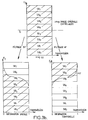
- FIG. 3b a group of frequency bands has been shown in the upper part, such as the group G0 for example, the notation of the sub-bands relative to the group index being deleted in order to facilitate reading.
- each sub-band is represented in increasing frequencies FY, in the vertical direction of the image on the ordinate, and in transmission value along the abscissa axis, the total transmission or absence of attenuation being represented by the value 1 and the total attenuation by the value 0.
- the sub-bands can have a bandwidth, in the vertical direction, different, but that the sub -bands SB3 SB4, SB2 SB5, SB6 SB1 and SB0 SB7 have the same bandwidth.
- step B consists in carrying out a high-frequency HF filtering and a low-frequency LF filtering of each group of sub-bands, so as to discriminate the spatial information and the time information of the source digital image.
- the low-frequency and high-frequency filtering operations can be carried out either by means of fixed filtering, a fixed filtering template being applied to all of the sub-bands of the group of sub-bands to perform the filtering required, as shown in FIG. 3b at low frequency, respectively at high frequency, that is, on the contrary, an adaptive filtering in which the filtering template implemented is adapted as a function of the value of a criterion of decision calculated as will be described later in the description.
- the aforementioned low-frequency, respectively high-frequency filtering has the effect of dissociating the spatial information from the temporal information both contained in the original interlaced source digital image, this image , for the purposes of the description, and the digital signal relating to this image, being noted imay.
- Steps C and D of recomposition of the source digital image spectrum respectively construction of an image in progressive format associated with at least each frame T1, T2, will now be described in a first embodiment consisting in carrying out this construction in the frequency domain, that is to say in the field of sub-bands.
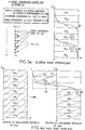
- the operation of recomposing the spectrum of the source digital image by spectral composition consists, as shown on the left side of FIG. 3c, in carrying out the aforementioned spectral composition taking into account the contribution of l evolution of the structure of the source digital image.
- the spectral composition operation consists in assigning the digital spatial information signal generated by the low-frequency filtering to the half-sum of the frequency spectra of the first and of the second image in progressive format, to generate a first spectrum of intermediate frequencies representative of the structure of the first or second image in progressive format.
- the low-frequency signal or LF part of the digital signal of the source image imay is represented, which also constitutes a first intermediate frequency spectrum representative of the structure of the first or of the second image in progressive format. More particularly, this frequency spectrum is equal to half a sum of the frequency spectra of the first and of the second image in progressive format.
- the operation of recomposing the spectrum of the source digital image also consists, as shown in the right part of FIG.
- the operation of redialing in the first embodiment considered, then consists in assigning the digital time information signal which is inverted frequently, that is to say tell the spectrum HF ⁇ , at half the frequency spectra of the first and second image in progressive format, to generate a second intermediate frequency spectrum representative of the evolution of the first image in progressive format associated with the first frame in the second progressive format image associated with the second frame.
- object of the present invention consisting in the construction in the frequency domain of an image in progressive format associated with at least each frame T1, T2 of the original source digital image
- l step D then consists, as shown in FIGS. 3d and 3e, of recomposing a first resulting frequency spectrum representative of the first image in progressive format, as well as represented in figure 3d, by linear combination of the first and second spectrum of intermediate frequencies and simultaneously to recompose a second resulting frequency spectrum, representative of the second image in progressive format, as represented in figure 3e, by linear combination of the first and of the second spectrum of intermediate frequencies.
- the first and second resulting frequency spectrum form the recomposed frequency spectrum.
- the aforementioned difference may be a weighted difference
- the digital values or digital signal representative of the first intermediate frequency spectrum LF, respectively of the second intermediate frequency spectrum HF ⁇ can be assigned arbitrary weighting coefficients depending on the type of scene and therefore progressive digital source image transmitted.
- the first progressive image thus obtained is a progressive image synchronized on the first frame T1 of the source digital image in interlaced format.
- the progressive image framed on the first frame T1 is nothing other than a version interpolated in the vertical direction of the first frame T1 of the current interlaced digital image imay.
- the first progressive image imap1 is therefore formed by the first frame T1 of the digital source image in interlaced format and by the points constructed in an intermediate position at half a frame step, due to the recomposition of the first resulting frequency spectrum represented by right part of figure 3d.
- the points reconstructed in the first frame T1 are symbolized by a rectangle. According to the conventions for representing the first and the second frame T1, T2, it is indicated that the first progressive image synchronized with the first frame T1 corresponds to the most earlier progressive image.
- the linear combination making it possible to carry out this recomposition can, in a nonlimiting manner, be formed by the sum of the first and second spectrum of intermediate frequencies.
- the first intermediate frequency spectrum LF with the sign + has been represented, and the second intermediate frequency spectrum HF ⁇ also assigned the + sign to symbolize the sum of the first and second spectrum of intermediate frequencies to constitute, by recomposition, the second resulting frequency spectrum.
- the second progressive image synchronized on the second has been symbolically represented in the image domain.
- the second progressive image imap2 in fact constitutes an interpolated version in the vertical direction of the second frame T2 of the source digital image imay.
- the second progressive image imap2 is formed by the points of the second frame T2 of the source digital image and by the points reconstructed in an intermediate position at half a step due to the composition, the addition in this case, the first and second spectrum of intermediate frequencies BF, HF.
- the reconstructed points are represented by circles on the frame T2.
- the second progressive image imap2, synchronized on the second frame T2, is designated as the most recent progressive image.
- the first resulting frequency spectrum and the second resulting frequency spectrum forming the recomposed frequency spectrum can then be subjected to an inverse frequency transformation, constitutive of step D of construction, as will be described later in the description .
- FIGS. 4a and 4b A more detailed description of a second embodiment of the method for converting from the interlaced format to the progressive format of a source digital image in interlaced format, object of the present invention, will now be given in conjunction with FIGS. 4a and 4b in the case where the construction, that is to say step D previously described in the description, is carried out in the image domain proper.
- step C consisting in carrying out a recomposition of the source digital image spectrum, consists in composing in the frequency domain, as represented in FIG. 4a, in the right part thereof, for each groups of sub-bands in the vertical direction, a resulting frequency spectrum representative of an interlaced dual image of the interlaced source digital image.
- the resulting frequency spectrum is obtained by difference of the digital spatial information signal, represented by the LF sub-band spectrum, affected by the + sign, generated by the low-frequency filtering and of the digital time information signal, HF spectrum, affected by the - sign, generated by the high-frequency filtering.
- This resulting frequency spectrum is representative of the dual digital image of the interlaced source digital image.
- This second embodiment of the method, object of the present invention is in fact based on the prior construction of the dual image of the source digital image. interleaved in the frequency domain, i.e. in the subband domain, and can be justified in the following manner.
- ima_spat designates the spatial information of the source digital image while ima_temp designates the temporal information contained in this same source image in interlaced format.
- FIG. 4a The operation of obtaining the spectrum of the imay dual image from the spectrum of the imay source digital image is shown in FIG. 4a.
- This figure illustrates exactly the difference of the two spectra in the high-frequency domain corresponding to the time offset of a frame separation interval ⁇ t of these images in the image domain.
- the construction of the progressive images is carried out after returning to the image domain.
- step D of the method which is the subject of the present invention then consists in performing an inverse frequency transform of the resulting frequency spectrum, representative of the dual image, in order to generate the digital dual image in the image domain in format intertwined.
- the method which is the subject of the present invention, in the second embodiment, then consists in reconstructing, as shown in FIG. 4b, from the source digital image and from the dual digital image, by position shift of a half-pixel in the vertical direction, a progressive format image associated with each of the first and second frames T1, T2.
- the elaboration of the two progressive images imap1, imap2 in the image domain is obtained from the preceding considerations by considering, for the progressive image 1, imap1, the points located on the first frame T1, of the source digital image and of the dual image of the source digital image, both in interlaced format, and for the second progressive image, imap2, the points located on the second frame T2 of the two aforementioned images.
- the result, obtaining the first and second progressive image imap1, imap2 is of course equivalent to the result of the first embodiment.
- the low-frequency and high-frequency filtering processes are implemented using filter elements using a single fixed filter template.
- An improved variant of the aforementioned first and second embodiments can however be carried out in order to effectively distinguish the HF time information due to the only movement of the structures or image elements from a high frequency nature information of spatial origin resulting from relatively slow movements or of moderate amplitude of very cut image elements.
- a fixed filtering applied to an image without movement, but rich in contours leads to discriminate the low-frequency spectrum from the spatial high-frequency spectrum when the whole spectrum should have been preserved, the contribution of information temporal to the high-frequency spectrum being absent in this particular case.
- a more elaborate conversion process takes into account the information linked to the sub-bands themselves and allows, according to a decision criterion, for spatial / temporal detection of the content. of the image, in particular of each sub-band, to make a choice between fixed or adaptive filtering according to the diagram represented in FIG. 5.
- the low and high-frequency filtering is an adaptive type filtering carried out according to a decision criterion of spatio-temporal detection of the inter- and / or intra-image content digital interlaced sources.
- the energy of its sub-band spectrum will be mainly concentrated in the low frequencies, which causes a displacement of the cut point in the opposite direction.
- the adaptive filtering mode thus defined therefore makes it possible to considerably improve the technique of converting interlaced / progressive format since this filtering mode takes account of the information present in the sub-bands of the sub-band division, this is that is to say, the specificity of the characteristics of each of the images processed as a function of the complexity of their content and of the energy of movement contained in them.
- object of the present invention in one or other of the embodiments previously described, it is understood of course necessary to implement particularly suitable filtering devices for performing fine filtering in the sub-bands obtained, following the frequency decomposition into sub-bands.
- any operation carried out in the sub-band domain may indeed be accompanied, during the reconstruction phase, by rebound phenomena on the contours or by parasitic frequencies disturbing the signal, these parasitic phenomena being linked to the partial overlapping of sub- neighboring bands.
- Filtering techniques in the sub-bands must then be used in order to limit these annoying faults during the implementation of a filtering operation of a digital signal.
- any high-pass filter becomes low-pass for the inverted version frequently and respectively, any low-pass filter becomes a high-pass filter.
- an object of the present invention is also the implementation of a device for filtering a digital signal having a frequency spectrum S according to a filtering template G as shown in the Figure 6a.
- the frequency spectrum S is that of the signal in the group of sub-bands considered, that is to say one of the groups of the decomposition into MN sub-bands for example.
- the filtering device then comprises a bank of filters for the frequency transformation of the digital signal into a number N of successive adjacent vertical sub-bands, covering the frequency spectrum S of the digital signal.
- This bank of filters is, as previously mentioned in the description, a bank of filters MOT making it possible to carry out the above-mentioned decomposition to obtain the frequency spectrum S formed by the group of sub-bands.
- each elementary filter is formed by a filter with an odd number of coefficients.
- Each elementary filter is formed by the combination of a low-pass filter and a high-pass filter, each weighted by the lower limit value, respectively upper, of global filtering attenuation G in the vicinity of the lower and upper limit. of the corresponding sub-band.
- the respectively lower upper limit value of attenuation is denoted a, b for the sub-band SB4, it is denoted b, c, and for the sub-band SB5, c, d, as shown in Figure 6b.
- the low-pass filter is a filter of the type 1 / p, 1 / q, 1 / p while the high-pass filter is a filter of the type -1 / r, 1 / s, -1 / r, p, q, r and s being integers greater than 1.
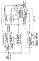
- FIGS. 7a and 7b A more detailed description of a device for converting a digital television image from the interlaced format to the progressive format, object of the present invention, will now be given in conjunction with FIGS. 7a and 7b, in two different embodiments allowing the implementation of the method, object of the present invention, in the first, respectively second embodiments, previously described in the description.
- the two embodiments represented in FIG. 7a notably comprise a module 1 of frequency transform by cutting up into at least one group of N frequency sub-bands of the source digital image in the vertical direction of this image, so as to generate from pixels constituting the source digital image a plurality of digital signals representative in each group of sub-bands, in the vertical direction, of the frequency spectrum of the aforementioned source digital image.
- the source digital image is of course in interlaced format.
- a high-frequency and low-frequency filter module 2 which receives the digital signals representative of the frequency spectrum of the source digital image delivered by the frequency transform module 1.
- the high and low frequency filtering module 2 makes it possible to discriminate between a digital spatial information signal and a digital information signal temporal generated by low filtering, respectively high-frequency.
- These signals are represented by BF, HF respectively. They are representative of the structure of the source digital image in the first and second frames, respectively of the evolution of this structure of the source digital image in the time interval separating the first and the second frame T1, T2 as previously mentioned in the description.
- a spectral recomposition module of the frequency spectrum of the source digital image by frequency processing 3 is provided, which allows, by spectral composition of the contribution of the evolution of the structure of the source image, digital HF signal, and of the spatial information signal, digital signal BF, to generate a recomposed frequency spectrum, as will be described below in the description.
- a module 4 for reconstruction in the image or frequency domain from the recomposed frequency spectrum is provided, to ensure the reconstruction of an image in progressive format associated with at least each frame, an image being reconstructed for the frame T1, respectively for the T2 frame.
- the frequency transform module 1 can comprise a switching circuit 10 receiving on an input the interlaced source image signal representative of the image digital interlaced source of television, and delivering on switching, on criteria of choice of filtering mode, adaptive or non-adaptive, the source image signal on a first, respectively a second output terminal.
- the circuit 10 is represented in the form of a test because it can consist, for example, of a digital switching circuit, which, from a binary type switching variable, makes it possible to route the signal input, source digital image signal, to one or the other of the outputs.
- filter modules by modulated orthogonal transform of MOT type filtering carried out under the conditions previously mentioned in the description, modules referenced 11 and 12 respectively, receive the source image signal delivered by one of the output terminals of the switching module. 10 and each allow the division into frequency sub-bands, for example into a group of N vertical sub-bands with regard to the module 11, these N sub-bands constituting a single group of sub-bands , or for the module 12 in M groups of N sub-bands as described previously in the description.
- the module 11 or the module 12 delivers a digital signal representative of the frequency spectrum of the source digital image.
- the frequency transform module 1 advantageously comprises a module 13 for calculating a decision criterion on the filtering template applied to the high-frequency and low-frequency filtering circuit as a function of the adaptive or non-adaptive mode chosen.
- the module 13 for calculating the decision criterion receives a signal representative of the distribution of the energy of the frequency spectrum into frequency sub-bands, this signal corresponding for example to a signal which is a function of the position of the cut-off point in the two-dimensional frequency space of the sub-bands as represented in FIG. 5.
- the module 13 for calculating the decision criterion makes it possible for example, as a function of the value of the signal representing the energy distribution, to deliver a digital signal of control of the high and low frequency filter module 2, as will be described below.
- the high and low-frequency filter module 2 can comprise, as shown in FIG. 7a or 7b, a low-frequency filter module 20 and a high-frequency filter module 21 receiving in parallel the digital signal representative of the frequency spectrum of the image digital interlaced source delivered by the frequency transform module 1.
- the high-frequency filter module 20 and the low-frequency filter module 21 receive on a control input the digital control signal delivered by the calculation circuit 13 of the criterion of decision on the filtering template.
- the digital control signal of the high-frequency filter module 20 and of the low-frequency filter module 21 makes it possible to switch the one and the other of the aforementioned filter modules 20 and 21 on the template values as defined previously in the description by the filter modes 4, 8 and 5, 6, 7 mentioned above.
- the module 3 of spectral recomposition of the frequency spectrum of the source digital image, by frequency processing comprises a module 30 d inversion receiving the digital HF time information signal delivered by the high-frequency filtering module 20 and delivering a digital signal of inverted time information HF ⁇ brought back into the low-frequency domain.
- a subtractor module 31 and a summing module 32 are provided in order to ensure the above-mentioned spectral recomposition.
- the subtractor module 31 receives the digital spatial information signal BF delivered by the low-frequency filtering module 21, as well as the inverted temporal information signal HF ⁇ delivered by the frequency inversion module 30.
- the summing module 32 receives the digital spatial information signal BF delivered by the low-frequency filtering module 21 as well as the digital reverse temporal information signal HF ⁇ delivered by the inversion module 30. It delivers a digital signal representative of the frequency spectrum of the second image in progressive format.
- the digital signals representative of the frequency spectrum of the first image and of the second image in progressive format, delivered by the subtracting circuit 31 and by the summing circuit 32 constitute the recomposed frequency spectrum, delivered by the redial module 3 .
- the frequency inversion module 30 consists of a filter whose coefficients are calculated, as mentioned previously in the description in conjunction with FIGS. 6a, 6b and 6c for example.
- the subtractor module 31 and the summing module 32 can then be produced either in the form of dedicated digital circuits, or in software form for example.
- the reconstruction module 4 in the frequency domain of an image in progressive format associated with each frame T1 respectively T2 comprises for example, as shown in FIG. 7a, in the case of the first embodiment, a module 41 and a module 42 of inverse frequency transform, that is to say a bank of filters of modulated orthogonal transform of MOT type, making it possible to ensure a perfect reconstruction of the images in progressive format in the image domain.
- a module 41 and a module 42 of inverse frequency transform that is to say a bank of filters of modulated orthogonal transform of MOT type, making it possible to ensure a perfect reconstruction of the images in progressive format in the image domain.
- a module 41 and a module 42 of inverse frequency transform that is to say a bank of filters of modulated orthogonal transform of MOT type
- Each inverse frequency transform module 41, 42 delivers, from the digital signals representative of the recomposed frequency spectrum, that is to say in fact from the digital signal representative of the frequency spectrum of the first respectively of the second image in progressive format, the first and second images in progressive format each associated with the frame T1, T2 respectively.
- the module 3 of spectral recomposition of the frequency spectrum of the source digital image, by frequency processing corresponds to module 3 of the embodiment of FIG. 7a in which the frequency inversion module 30 has been eliminated.
- the subtractor module 31 and the summing module 32 although the latter summing module 32 is not essential, receive respectively the high frequency digital signal HF delivered by the high frequency filtering module 20 directly, as well as the low-frequency digital signal LF delivered by the low-frequency filtering module 21.
- the subtractor module 31 then delivers a digital signal representative of the frequency spectrum of an interlaced dual image of the source digital image in interlaced format.
- the module 4 for reconstruction in the image domain of an image in progressive format associated with at least each frame, in particular with the first T1 and the second frame T2 respectively, comprises a module 41 of inverse frequency transform, controlled as a function of the filtering mode, adaptive or non-adaptive, chosen.
- This module receives the signal representative of the frequency spectrum of the dual image and delivers in the image domain a signal representative of the digital dual image in interlaced format.
- a pixel combination circuit 43 is provided, which receives the digital signal representative of the source digital image in interlaced format as well as, of course, the signal representative of the dual digital image in interlaced format, and allows by combination of pixels of these two images to deliver a first and a second progressive image associated with the first, respectively with the second frame of the source digital image, as described previously in the description in conjunction with FIGS. 5a and 5b.
- the module 43 for combining the pixels of the two above-mentioned interlaced images can advantageously be produced from three memory spaces, or storage units.
- the first storage unit receives the information relating to the pixels of the source digital image in interlaced format
- the second storage unit receives the values of the pixels relating to the dual image in interlaced format.
- the third storage unit receives, by read-write addressing, the pixel values of the first two T1 frames of the source digital image and of the dual image, according to a successive addressing suitable for reading the first and second aforementioned storage units. , respectively the pixel values of the two second T2 frames of these same two images, according to the same read addressing procedure of the same two first and second storage units, to constitute the first respectively the second progressive image, as described above in the description in conjunction with Figures 4a and 4b.
- FIGS. 8a, 8b, 8c and 8d A more detailed description of a hierarchical type motion estimation process of a sequence of television images will now be given in conjunction with FIGS. 8a, 8b, 8c and 8d, this process corresponding to a particularly advantageous application of the process or device for converting a digital television source image from the interlaced format to the progressive format, objects of the invention, that is to say use of the aforementioned process or device.
- FIG 8a there is shown a flowchart general of the aforementioned application, that is to say of the use of the interlaced / progressive format conversion method for carrying out an estimation of movement between images of a sequence of television images.
- this application for estimating and compensating for movement between a current source image and a previous source image of a sequence of television images coded in the form of a digital image signal and each having a full resolution denoted R, consists, in a first phase, in subjecting in a step a) the current and previous source images, to a process of change of resolution to generate a current source image respectively of lower resolution, this resolution being noted Rxq n where q ⁇ ] 0.1 [, n being a positive or zero integer, as will be explained later in the description.
- FIG. 8a it is indicated that the previous source image in interlaced format is referenced im (t) and the current source image in interlaced format is referenced im (t + 1).
- step b) the application to a motion estimation process as shown in FIG. 8a consists in performing a step b), which consists in performing a motion estimation by blocks by comparison of the current images and previous lower resolution, same resolution, to generate a set of intermediate motion vectors representative of the movement between corresponding blocks of the current and previous images of lower resolution.
- step c) consisting in establishing, on the basis of a selection criterion, from the set of intermediate motion vectors denoted vect n a set of estimated vectors, best estimate of the movement between current and previous source image of lower resolution, of the same resolution.
- step c) is itself followed by a test step on the level of resolution.
- step c) previously mentioned is then followed by a step d) consisting in carrying out a plurality of iterations of rank n + 1 of the steps a) to c) previously described, from the current and previous source image and the estimated vectors, to generate a set of candidate motion vectors, noted V cdt , representative of a rough estimate of the movement between current and previous full resolution images.
- the candidate motion vectors are denoted V cdt and correspond to a rough estimate of the motion between current source image im (t + 1) and previous image source im (t).
- the application of the format conversion method, object of the present invention further consists, in order to carry out the motion estimation, in carrying out a second phase starting from the set of candidate vectors representative of the rough estimate of the movement of the current and previous images at full resolution.
- the second phase can consist in carrying out a step e), which consists in generating, from a previous image decoded in interlaced format, a previous image decoded in progressive format, associated with each frame T1, T2 of the previous source image im (t).
- the motion estimation process in the application in question is intended to be used in an image coding device for the transmission of the above-mentioned television images.
- the operations necessary to obtain the previous decoded image are shown in dotted lines in FIG. 8a, these operations being normally implemented at the level of the coder but not strictly speaking part of the motion estimation process, object of the present invention.
- the previous decoded image is obtained from the previous source image by an encoding operation carried out with a view to transmission and a decoding operation, consecutive to the aforementioned encoding operation, this decoding operation having for object to reconstruct an approximation of the previous image, necessary at the level of the decoder, to obtain the decoding of the transmitted image.
- step e) also includes an initialization phase making it possible to initialize a resolution parameter p to a value 2 for example.
- Step e) of the second phase is then followed by a step f) consisting of generating, from the previous image decoded in progressive format obtained at the end of step e), a first and a second grid associated with the first frame T1 respectively with the second frame T2 of the previous decoded interlaced image.
- step f) consists, for example, from the previous interlaced decoded image, the interlaced / progressive format change operation having the effect of causing an offset d half a pixel in the frame in the vertical direction as described previously in the description, to perform a step 4001 of shifting by 1 / p pixel in the horizontal direction of the progressive image, this shift constituting an interpolation in the direction horizontal of the image, followed as a function of the value of the parameter p by a shift of 1 / p pixel in the vertical direction of the progressive image in order to perform an interpolation in the vertical direction Y.
- This shift operation in Y is denoted 4002 in FIG. 8a.
- the two operations 4001 and 4002 thus make it possible to obtain, from the previous image decoded in progressive format under the conditions previously described in the description, the first and second grids synchronized on the frame T1 respectively T2 of the previous decoded image. interleaved above, these two grids being memorized in a step 4003 as described in FIG. 8a, these grids corresponding to progressive images interpolated in step 1 / p, in the vertical Y and horizontal X directions.
- the application to motion estimation, object of the present invention comprises a step g) consisting in carrying out, starting from the first and from the second frame of the current source image and from the first and from the second grid, an estimate of final local movement by prediction of intra-frame and / or inter-frame movement between first frame and first grid, second frame and second grid, respectively first frame and second grid and second frame and first grid.
- step g) is carried out in the progressive interpolated image of step 1 / p.
- step h) is followed by a test operation relative to the effective resolution of each of the grids obtained at the end of step f).
- the candidate motion vectors make it possible to obtain final candidate motion vectors, which can advantageously be discriminated in the following manner.
- Step g) can thus be followed by a test on the realization of the intra or inter-frame motion estimation.
- the intra-frame estimation being carried out first, as long as the inter-frame estimation is not carried out as shown in the test i) represented in FIG. 8a, that is to say in negative response in this test, a memorization of the intra-frame parameters can be carried out with return to the initialization step of the first phase.
- a step j) of comparison between the intra / inter-frame motion vectors can be performed to finally obtain the final vector for each frame block at fractional pixel precision 1 / p.
- step a) of the first phase has been shown, making it possible to carry out the process of changing resolution, by decimation.
- the process of changing resolution can be carried out by subjecting each current and previous source image to a frequency transform by decomposition into MxN frequency sub-bands in the directions horizontal and vertical of each image, to generate a respectively vertical horizontal spectrum signal representative in each group of horizontal respectively vertical sub-bands of the frequency spectrum of the current image and of the previous image.
- This sub-band decomposition step is followed a step of filtering and selective recomposition in the horizontal and vertical directions of the MxN sub-bands of the current source image, respectively of the previous source image by linear combination, to generate for each current and previous source image, a filtered and recomposed frequency spectrum signal comprising for example M'xN 'sub-bands with M' ⁇ M, N ' ⁇ N.
- the filtering and selective recomposition in direction X is of the form 4: 0 and in direction Y of the form 3: 1.
- a quarter of the sub-bands of the MxM decomposition are thus set to zero, the totally attenuated and unused sub-bands being shown in gray.
- the remaining sub-bands those located in the border area with the removed sub-bands which can be subjected to sub-band filtering in order to limit any polluting effect when returning to the image domain, are grouped together to constitute a filtered frequency spectrum. and recomposed M'xN 'and are then subjected to an inverse frequency transform, on M / 2.M / 2 sub-bands, in the particular case of FIG. 8b.
- This inverse frequency transform makes it possible to generate a current and previous low-resolution source image, that is to say of lower resolution, as described previously in the description.
- the previous and current images thus obtained are interlaced images in lower resolution.
- steps 2001 and 2002 allowing the implementation of step b) of estimation of intra or inter-frame type at full pitch, it is indicated that these steps are normally steps of conventional type carried out on the images of successive lower resolution, in interlaced format.
- this step essentially consists in adapting the number of vectors and their size to the successive lower resolution images.
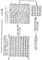
- the processing thus carried out is particularly advantageous insofar as, from an image signal I (m) of the image domain, the frequency transform of odd PRMF type in the domain of the sub-bands generates a signal X k (m) and the even reverse PRMF transform in the sub-band domain re-generates in the image domain the signal S (m) which, by superposition with the signal I (m), makes it possible to constitute the complete grid at the step of a half-pixel, as shown in Figure 8c.
- step 4003 The construction of the grids synchronized on the frames T1 and T2 of the previous image is carried out in step 4003 by storing complete grids in half-pixel steps as shown in Figure 8c, as shown in Figure 8d.
- the method and the device, objects of the present invention are particularly advantageous insofar as, by simple manipulation carried out on the sub-bands following a decomposition into sub-bands of the image signals, very complex processes such as the processes of motion estimation can be implemented with additional reliability and precision of motion estimation compared to those of motion estimates of conventional type commonly used; on the other hand, the method and the device, objects of the present invention, are also particularly advantageous insofar as, for the same reasons, relatively simple interlaced / progressive format conversion processes can be implemented with results comparable with conventional conversion operations used in the production studio, however much more complex, as long as the movement does not have too large a amplitude.
Landscapes
- Engineering & Computer Science (AREA)
- Computer Graphics (AREA)
- Multimedia (AREA)
- Signal Processing (AREA)
- Television Systems (AREA)
Applications Claiming Priority (2)
| Application Number | Priority Date | Filing Date | Title |
|---|---|---|---|
| FR9411131 | 1994-09-19 | ||
| FR9411131A FR2724802B1 (fr) | 1994-09-19 | 1994-09-19 | Procede et dispositif de conversion d'une image numerique de television du format entrelace au format progressif et leurs applications |
Publications (1)
| Publication Number | Publication Date |
|---|---|
| EP0702488A1 true EP0702488A1 (de) | 1996-03-20 |
Family
ID=9467047
Family Applications (1)
| Application Number | Title | Priority Date | Filing Date |
|---|---|---|---|
| EP95402087A Withdrawn EP0702488A1 (de) | 1994-09-19 | 1995-09-15 | Verfahren und Vorrichtung zur Umsetzung eines digitalen Fernsehbildes vom Zeilensprungformat in ein progressiv abgetastetes Format und dessen Verwendungen |
Country Status (2)
| Country | Link |
|---|---|
| EP (1) | EP0702488A1 (de) |
| FR (1) | FR2724802B1 (de) |
Cited By (1)
| Publication number | Priority date | Publication date | Assignee | Title |
|---|---|---|---|---|
| EP1253785A2 (de) | 2001-04-26 | 2002-10-30 | British Broadcasting Corporation | Verbesserung des Standards eines durch Rasterabtastung erzeugten Videosignals und Zeilensprung zur sequentiellen Abtastumsetzung |
Citations (4)
| Publication number | Priority date | Publication date | Assignee | Title |
|---|---|---|---|---|
| GB2251756A (en) * | 1991-01-11 | 1992-07-15 | Sony Broadcast & Communication | Compression of composite colour video signals |
| EP0531242A1 (de) * | 1991-09-03 | 1993-03-10 | France Telecom | Adaptives Filterverfahren eines in Teilbändern transformierten Signals und entsprechende Filteranordnung |
| EP0586262A1 (de) * | 1992-09-04 | 1994-03-09 | Kabushiki Kaisha Toshiba | Fernsehsignalprozessor |
| EP0595710A1 (de) * | 1992-10-29 | 1994-05-04 | France Telecom | Verfahren und Gerät zur Segmentierung in Teilbändern und zur Wiederherstellung eines digitalen Signals und entsprechende Vorrichtung |
-
1994
- 1994-09-19 FR FR9411131A patent/FR2724802B1/fr not_active Expired - Fee Related
-
1995
- 1995-09-15 EP EP95402087A patent/EP0702488A1/de not_active Withdrawn
Patent Citations (4)
| Publication number | Priority date | Publication date | Assignee | Title |
|---|---|---|---|---|
| GB2251756A (en) * | 1991-01-11 | 1992-07-15 | Sony Broadcast & Communication | Compression of composite colour video signals |
| EP0531242A1 (de) * | 1991-09-03 | 1993-03-10 | France Telecom | Adaptives Filterverfahren eines in Teilbändern transformierten Signals und entsprechende Filteranordnung |
| EP0586262A1 (de) * | 1992-09-04 | 1994-03-09 | Kabushiki Kaisha Toshiba | Fernsehsignalprozessor |
| EP0595710A1 (de) * | 1992-10-29 | 1994-05-04 | France Telecom | Verfahren und Gerät zur Segmentierung in Teilbändern und zur Wiederherstellung eines digitalen Signals und entsprechende Vorrichtung |
Cited By (2)
| Publication number | Priority date | Publication date | Assignee | Title |
|---|---|---|---|---|
| EP1253785A2 (de) | 2001-04-26 | 2002-10-30 | British Broadcasting Corporation | Verbesserung des Standards eines durch Rasterabtastung erzeugten Videosignals und Zeilensprung zur sequentiellen Abtastumsetzung |
| EP1253785A3 (de) * | 2001-04-26 | 2004-07-28 | British Broadcasting Corporation | Verbesserung des Standards eines durch Rasterabtastung erzeugten Videosignals und Zeilensprung zur sequentiellen Abtastumsetzung |
Also Published As
| Publication number | Publication date |
|---|---|
| FR2724802B1 (fr) | 1997-01-17 |
| FR2724802A1 (fr) | 1996-03-22 |
Similar Documents
| Publication | Publication Date | Title |
|---|---|---|
| EP0542974B1 (de) | Teilband-Koder und Dekoder für Fernsehsignale mit verschiedenen Auflösungswerten. | |
| US8385665B2 (en) | Image processing apparatus, image processing method, program and semiconductor integrated circuit | |
| EP0271122B1 (de) | Verfahren zur Übertragung von Hochauflösungsfernsehbilder in engen Bandkanälen und Sender und Empfänger dafür | |
| FR2660139A1 (fr) | Procede de codage et de transmission a au moins deux niveaux de qualite d'images numeriques appartenant a une sequence d'images, et dispositifs correspondants. | |
| EP0330279A1 (de) | Einrichtung zur raumzeitlichen Unterabtastung von digitalen Videosignalen, die eine Folge verschachtelter oder sequentieller Bilder darstellen, Übertragungssystem von Fernsehbildern mit hoher Auflösung mit einer solchen Einrichtung und Stufen zum Senden und Empfangen in einem solchen System | |
| EP3318061B1 (de) | Verfahren zur bildcodierung und einrichtung zur durchführung des verfahrens | |
| EP2815281B1 (de) | Verfahren zur codierung eines holographischen musters und zugehörige codierungsvorrichtung und computerprogramm | |
| FR2651402A1 (fr) | Dispositif de conversion de frequence trame et du nombre de lignes pour un recepteur de television haute definition. | |
| EP0412003B1 (de) | Vorrichtung zur Umwandlung einer Bewegungsinformation in ein Bewegungsdetektionssignal mit gewünschter Zeilenanzahl und Halbbildfrequenz für einen Hochauflösungsfernsehempfänger | |
| FR2584553A1 (fr) | Appareil pour reduire le bruit d'un signal video composite et filtre recursif qui y est utilise | |
| EP0347325A1 (de) | Verfahren und Installation zur Sendung von kompatiblen Hochauflösungsfernsehprogrammen | |
| EP0337564B1 (de) | Einrichtung zur Dekodierung von Signalen, die eine Folge von Bildern darstellen und Übertragungssystem von Fernsehbildern mit hoher Auflösung mit einer solchen Einrichtung | |
| FR2670348A1 (fr) | Dispositif de codage d'images appartenant a une sequence d'images, a rearrangement des lignes avant transformation mathematique, systeme de transmission d'images, recepteur et procede de codage correspondants. | |
| EP0316232B1 (de) | Verfahren und System zur Übertragung eines Programms mit hoher Auflösung | |
| EP0702488A1 (de) | Verfahren und Vorrichtung zur Umsetzung eines digitalen Fernsehbildes vom Zeilensprungformat in ein progressiv abgetastetes Format und dessen Verwendungen | |
| EP0691065B1 (de) | Kompatible teilbandkodierung/dekodierung von fernsehbildern | |
| WO1990000846A1 (fr) | Codage et decodage d'images de television a haute definition | |
| FR2638926A1 (fr) | Procede, dispositif de codage numerique d'images de tele a haute definition; dispositif de decodage correspondant, systeme de transmission d'images equipe d'un etage d'emission et d'un de reception incluant un tel dispositif de codage ou de decodage; etages d'emission et de reception comprenant de tels dispositifs | |
| FR2560699A1 (fr) | Appareil de traitement de signaux en pyramide hierarchique en temps reel | |
| FR2886787A1 (fr) | Procede et dispositif de codage et de decodage d'une sequence d'images | |
| FR2654887A1 (fr) | Procede et dispositif de codage et de decodage compatibles d'images de television de resolutions differentes. | |
| WO2019057368A1 (fr) | Procedes de codage et de decodage d'une image | |
| EP1766999B1 (de) | Verfahren und vorrichtung zur kodierung einer videosequenz | |
| FR2832568A1 (fr) | Convertisseur numerique de frequence d'echantillonnage | |
| EP0448450A1 (de) | Verfahren und Vorrichtung zur Kodierung und Dekodierung eines digitalen hoch-auflösenden Breitbandfernsehsignals |
Legal Events
| Date | Code | Title | Description |
|---|---|---|---|
| PUAI | Public reference made under article 153(3) epc to a published international application that has entered the european phase |
Free format text: ORIGINAL CODE: 0009012 |
|
| 17P | Request for examination filed |
Effective date: 19960118 |
|
| AK | Designated contracting states |
Kind code of ref document: A1 Designated state(s): DE GB |
|
| RIN1 | Information on inventor provided before grant (corrected) |
Inventor name: SOYER, PATRICE Inventor name: MAU, JOEL |
|
| GRAG | Despatch of communication of intention to grant |
Free format text: ORIGINAL CODE: EPIDOS AGRA |
|
| 17Q | First examination report despatched |
Effective date: 19980714 |
|
| GRAG | Despatch of communication of intention to grant |
Free format text: ORIGINAL CODE: EPIDOS AGRA |
|
| GRAH | Despatch of communication of intention to grant a patent |
Free format text: ORIGINAL CODE: EPIDOS IGRA |
|
| STAA | Information on the status of an ep patent application or granted ep patent |
Free format text: STATUS: THE APPLICATION IS DEEMED TO BE WITHDRAWN |
|
| 18D | Application deemed to be withdrawn |
Effective date: 19990116 |