EP0702503A2 - Support pour élément de chauffage d'un fourneau électrique - Google Patents
Support pour élément de chauffage d'un fourneau électrique Download PDFInfo
- Publication number
- EP0702503A2 EP0702503A2 EP95305842A EP95305842A EP0702503A2 EP 0702503 A2 EP0702503 A2 EP 0702503A2 EP 95305842 A EP95305842 A EP 95305842A EP 95305842 A EP95305842 A EP 95305842A EP 0702503 A2 EP0702503 A2 EP 0702503A2
- Authority
- EP
- European Patent Office
- Prior art keywords
- post
- furnace
- support
- heater element
- ceramic
- Prior art date
- Legal status (The legal status is an assumption and is not a legal conclusion. Google has not performed a legal analysis and makes no representation as to the accuracy of the status listed.)
- Granted
Links
Images

Classifications
-
- H—ELECTRICITY
- H05—ELECTRIC TECHNIQUES NOT OTHERWISE PROVIDED FOR
- H05B—ELECTRIC HEATING; ELECTRIC LIGHT SOURCES NOT OTHERWISE PROVIDED FOR; CIRCUIT ARRANGEMENTS FOR ELECTRIC LIGHT SOURCES, IN GENERAL
- H05B3/00—Ohmic-resistance heating
- H05B3/62—Heating elements specially adapted for furnaces
- H05B3/66—Supports or mountings for heaters on or in the wall or roof
Definitions
- This invention relates to mounting of electric strip heating elements in high temperature vacuum or protective atmosphere furnaces.
- Electric heating elements in high temperature vacuum furnaces are often made of strips of sheet molybdenum or the like. Electrical contact may be made to the ends of a long metal strip which wraps around the hearth of the furnace. Such a long heating element requires mechanical support intermittently along its length to hold it in proper position in the furnace and for preventing shorting to other parts of the furnace or the load being heated in the furnace.
- Some heater supports have relied on an insulated post, or the like, extending through a hole in the strip heater. Although good mechanical support can be provided with such an arrangement, the hole is quite undesirable. The hole necessarily results in the heater having a narrower effective width at the location of the hole. Since there is less metal cross-section to carry the heating current, there is excess heating around the hole. This excess heating can be severe enough to burn out a heater under some circumstances and, if nothing else, it shortens the heater lifetime in that region. Heater elements most commonly fail at the end electrical contacts or in proximity to such holes.
- a type of heater support that does not require holes through the heater element is in a general form of a T.
- a sheet metal "post" forms the leg of the T, and the heater element lies on top of the top crossbar of the T.
- the heater element is secured to the crossbar by a rod lying on top of the heater element with twisted wires securing the bar to the crossbar of the T.
- Ceramic sleeves insulate the crossbar from the leg of the T to provide a compliant connection. Supports shown in the Kreider and Cyrway patents are of this general type.
- Such heater supports have been plagued with deformation problems. There is insufficient rigidity in the T-shaped mounting to support the heater element as it tries to move under the forces of thermal expansion, cooling gas flow, mechanical vibrations, and the like. The crossbar of the T tends to tilt relative to the leg, which may result in shorting of the heater element to other parts of the furnace structure or the load in the furnace. Breakage is also a problem when attempting to remove or replace the heater element supports. In high-temperature furnaces, heater elements, heat-shields and supports for the heater elements are often made of molybdenum. This material becomes quite brittle after heating to elevated temperatures.
- the heater support must also accommodate dimensional changes in the heater and the furnace. Typically, one part of the support is at relatively low temperature, while another part is at relatively high temperature. The heater element itself undergoes thermal expansion as it is heated. The consequent dimensional changes must be accommodated by the support without applying large mechanical loads on the brittle heating element, which could result in breakage.
- U.S. Patent No. 4,771,166 has provided an excellent support for an electric heating element in a vacuum furnace.
- the heater support has two similar support assemblies spaced apart with a rigid bridge compliantly mounted therebetween.
- the heater strip is compliantly connected to the bridge.
- Each of the mounting assemblies has a metal post connected to the heating chamber of the furnace and surrounded by a ceramic sleeve.
- the ceramic sleeve is surrounded by two ceramic tubes which hold the end of the bridge.
- a mechanical support for an electric heating element in a vacuum furnace or the like which comprises a ceramic post having an internal thread in its outer end, A threaded rod secured to a portion of the furnace engages the internal thread of the post for mounting the support.
- a transverse member at the inner end of the post includes a straight surface normal to the length of the post for engaging a flat heater element. The heater element is secured to the straight surface by, for example, a rod over the heater element which is secured to the transverse member by twisted wires.
- the post and transverse member are integral and form a T-shaped ceramic support.
- the post has a transverse slot in its inner end of the post and an L-shaped metal sheet has one leg of the L in the slot and the other leg of the L forming the flat surface.
- a second ceramic post identical to the first post is spaced apart from the first post.
- a transverse metal member extends between the first and second posts to form the flat surface, forming a U-shaped support for the heater element.
- An exemplary vacuum furnace comprises a horizontal cylindrical shell 10 having a sealing flange 11 at the end, against which a door (not shown) is sealed to close the furnace.
- the furnace illustrated in FIG. 1 is schematic and does not include a variety of conventional features such as support legs, doors, vacuum pumps, water cooling jackets, gauges, power supplies, etc., which are not required for an understanding of this invention. The drawing simply shows the general location of the heater elements and their supports employed in practice of this invention.
- the hot zone 12 comprises a double walled sheet metal plenum 16 into which cooling gas can be circulated for rapid cooling of the hot zone and its contents.
- thermal insulation 17 Inwardly from the plenum is a layer (or layers) of thermal insulation 17 which may be in the form of a plurality of parallel metal radiation shields, fibrous ceramic insulating "wool”, graphite "wool”, or ceramic or graphite insulating sheets. Regardless of the insulation employed in the hot zone, the innermost face is typically formed of sheet metal or flexible graphite sheet (Grafoil) which may be bonded to other materials. Such thermal insulation is conventional and need not be further described for an understanding of this invention.
- a plurality of electrical heating elements 18 extend circumferentially around the interior of the hot zone.
- Similar upper heating elements 18b extend around the upper half of the hot zone.
- Each heating element has conventional bolted electrical contacts 15 at each end for passing electric current through the heating element.
- Each heating element is mechanically supported between its ends by a plurality of supporting assemblies 19 illustrated in greater detail in the other drawings.
- a plurality of furnace load supporting structures 20 extend from the furnace shell between the heater elements into the hot zone. Baskets of parts (not shown) or other objects to be heated are placed on such supporting structures when the furnace is in use.
- a furnace such as illustrated in FIG. 1 may have a hot zone with a 1.5 meter diameter. Supports for the heating elements are spaced in the order of 30 cm. apart around the hot zone. Typical molybdenum heating elements are from 6 to 15 cm. wide. Four or more such heating elements are spaced along the length of the hot zone, depending on its total length. Such heating elements are generally not a continuous semi-circle, but instead are formed as a plurality of straight sections between adjacent support assemblies, with a small straight section adjacent to each support assembly. Small angle bends are sufficient to form such a heating element for an exemplary 1.5 meter diameter furnace. Such bends are readily made on a break and avoid the need for rolls for rolling a continuously curved heating element.
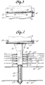
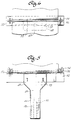
- FIGs. 2 to 4 An exemplary T-shaped heater support is illustrated in FIGs. 2 to 4.
- the side elevation view of FIG. 2 looks at such a support assembly circumferentially around the hot zone, that is, along the length of the heating element 18.
- the portion of the heater support that connects to the heating chamber of the furnace is referred to as the outer portion since it is radially outward in a circular furnace as illustrated herein.
- the opposite end that extends toward the center of the heating chamber is referred to as the inner portion.
- the plenum 16 around the heating chamber is formed by an outer sheet metal wall 23 and an inner sheet metal wall 24. Typically, these walls are steel rolled into a cylinder.
- a steel tube 26 extends through the plenum and is welded to the inner and outer plenum walls at the location of each mounting assembly. Additional spacers between the sheets may be employed, but other details of the plenum are not required for an understanding of this invention.
- a stainless steel nut 27 is welded into the outer end of the tube 26.
- a molybdenum rod 28 with roll formed threads is threaded into the nut and extends inwardly toward the center of the furnace. Molybdenum is used for this and other structural elements which may be exposed to elevated temperatures because of its ability to withstand the temperatures encountered in the vacuum furnace. Depending on the temperature requirements for the furnace, the various metal and ceramic parts may be fabricated of lower cost materials than the molybdenum, stainless steel and alumina mentioned herein.
- One type of thermal insulation commonly employed in vacuum furnaces comprises a plurality of sheet metal radiation shields 29.
- a vacuum radiation is the principal mechanism of heat transfer.
- a plurality of reflective radiation shields can be quite effective in providing a temperature gradient between the inner hot zone of the furnace and the surrounding shell.
- five such radiation shields are employed inwardly of the plenum walls, which themselves act as radiation shields.
- U-shaped sheet metal spacers 31 keep the radiation shields spaced apart from each other.
- Three or four innermost radiation shields and spacers may be fabricated of molybdenum while the outer ones are safely fabricated of less expensive stainless steel.
- the radiation shields and spacers each have a hole for providing ample clearance around a ceramic post 32 of the heater element support to permit shifting of the shields due to thermal expansion without applying loads on the heater support.
- a high-temperature ceramic such as alumina or alumina-based composition is preferred for the heater support.
- An exemplary ceramic composition which is commercially available from Coors Ceramics Co. of Golden, Colorado, is 97.3% alumina. It is a feature of the ceramic used for the heater support that it can be molded and/or machined to complex shapes, including threads.
- Lower alumina ceramics may be used for lower cost, it being recognized that 100 or more heater supports may be used in an exemplary furnace. Cost, however, is not a great concern since the improved heater element supports provide a prolong lifetime for the heater elements in the furnace and the time before it is necessary to rebuild the heater system of the furnace can be significantly prolonged.
- the post 32 of the heater support has an axial passage 33 through the full length of the post.
- the outer end of the passage includes an internal thread 34 so that the ceramic post can be threaded onto the molybdenum rod 28.
- the passage has a large diameter counterbore 36 near its inner end, thereby reducing the wall thickness of the ceramic for minimizing heat transfer.
- a flat transverse member 37 is integral with the post so that the heater support is T-shaped.
- the transverse member is further connected to the post by integral diagonal wings 38.
- the top surface of the T is flat.
- the transverse member could have a shallow V-shape in traverse cross-section (viewed as in FIG. 4) as long as there is a straight central line for supporting a heater element.
- the heater element 18 which is, for example, a sheet of molybdenum, is bent in a shallow V-shape adjacent the heater support so that the heater element extends straight from support to support around the inside of the furnace.
- the heating element rests on top of the crossbar of the T-shaped heater support. It is compliantly secured to the crossbar by a molybdenum retaining rod 39 which has a length greater than the width of the heating element.
- Each end of the retaining rod has an L-shaped bend, and the rod is tied to the bridge by twisted loops of molybdenum wire 42 extending through holes 41 near each end of the crossbar. There are no holes in the heating element.
- the heating element may not be completely flat but may have stiffening ridges bent into the sheet metal extending along its length.
- the retaining rod in such an embodiment lies atop the stiffening ridges.
- the ceramic post is threaded onto the molybdenum rod about 2.5 cm.
- the connection is stopped before the outer end of the post engages the inner wall 24 of the plenum or the end of the tube 26 through the plenum.
- the support can tilt or rotate slightly as required to accommodate thermal expansion variations that would otherwise apply undue loads on the heating elements.
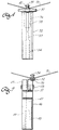
- FIGS. 5 to 7 illustrate another embodiment of T-shaped heating element support having a ceramic post connected to the cooling gas plenum by a threaded connection.
- a round ceramic post has an axial passage 47 through the full length of the post for reducing heat transfer and aiding in forming an internal thread 48 at the outer end of the post.
- the connection of the post to the furnace by a threaded rod is not illustrated in these drawings since the connection is essentially identical to the connection hereinabove described and illustrated in FIG. 2.
- the thread on the outside of the post serves to receive one or more ceramic or graphite nuts used to hold radiation shields or other thermal insulation in place. This minimizes the need for separate mounting pins for the insulation.
- Such an external thread may be used on other embodiments of post as well.
- the inner end of the post has an enlarged somewhat T-shaped head 49 which is generally rectangular in transverse cross-section (FIG. 6).
- a transverse slot 51 extends the full length of the rectangular head.
- An L-shaped sheet 52 of molybdenum has one leg of the L in the slot, the sheet of molybdenum is loosely held in place by a pair of molybdenum wires 53 passed through aligned holes in the head of the post and sheet respectively. The ends of the wire are bent over to keep them in place.
- the other leg of the L-shaped sheet of molybdenum forms the flat surface of the crossbar of the T to which the heater element is attached.
- the heater element 18 is compliantly secured to the molybdenum sheet by a retaining rod 54 compliantly tied to the sheet by retaining wires 56.
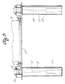
- FIG. 8 Similar principles are employed for constructing a U-shaped heater element support which can be used for retrofitting furnaces originally constructed with heater element supports as described and illustrated in U.S. Patent No. 4,771,166.
- a pair of substantially identical ceramic posts 61 Each of the posts includes an axial passage 62, the outer end of which includes an internal thread 63.
- the ceramic posts are each mounted to the gas plenum of the furnace by a threaded rod (not illustrated in FIG. 8) passing through a nut welded to the gas plenum as hereinabove described and also as employed in Patent No. 4,771,166.
- each of the ceramic posts has an external thread 64.
- a ceramic nut 66 on this external thread holds a sheet molybdenum bridge 67 between the two posts.
- the heater element 18 is compliantly secured to the bridge by a molybdenum retaining rod 68 tied to the bridge by twisted loops of molybdenum wire 69.
- the nut is not threaded tightly against the molybdenum bridge so as to accommodate thermal expansion.
- a molybdenum key wire passed through a hole transverse to the post may be used for retaining the nut on the external thread of the post.
- a ceramic post threaded onto a rod attached to the gas plenum provides good electrical insulation between the heating element and adjacent metallic parts of the furnace.
- Metallizing of the ceramic during operation of the furnace is not a problem.
- the outer end of the ceramic rod passes through holes in the radiation shields or other thermal insulation employed in the furnace. The insulation shadows the outer end of the rod and thereby, prevents any appreciable deposition of metal.
- the outer end of the ceramic post is not in contact with the gas plenum. The only contact with electrically conductive structure is to the threaded rod in the outer end of the post and the face of the post surrounding the rod is amply protected from metallizing.
- the exemplary furnace is just one of many possible embodiments.
- Such a furnace may have a vertical cylindrical shell or be rectangular or have any desired shape or size. It may be a bottom loading or top loading furnace instead of the end loading furnace as illustrated.
- the electrical heating elements may extend substantially completely around the circumference of the hot zone. On larger furnaces, heating elements may extend less than half way around the hot zone. Continuous strip heating elements may be used which make repeated paths around the furnace or which are connected for three phase power.
- Such heater supports may also be used for supporting intermediate portions of sinusoidal heating elements which traverse longitudinally through the furnace shell. They may also be used for supporting parts of flat heating elements in rectangular furnaces.
Landscapes
- Resistance Heating (AREA)
- Furnace Details (AREA)
Applications Claiming Priority (2)
| Application Number | Priority Date | Filing Date | Title |
|---|---|---|---|
| US308758 | 1994-09-19 | ||
| US08/308,758 US5497394A (en) | 1994-09-19 | 1994-09-19 | Electric heater element support |
Publications (3)
| Publication Number | Publication Date |
|---|---|
| EP0702503A2 true EP0702503A2 (fr) | 1996-03-20 |
| EP0702503A3 EP0702503A3 (fr) | 1996-07-10 |
| EP0702503B1 EP0702503B1 (fr) | 2000-04-05 |
Family
ID=23195277
Family Applications (1)
| Application Number | Title | Priority Date | Filing Date |
|---|---|---|---|
| EP95305842A Expired - Lifetime EP0702503B1 (fr) | 1994-09-19 | 1995-08-22 | Support pour élément de chauffage d'un fourneau électrique |
Country Status (3)
| Country | Link |
|---|---|
| US (1) | US5497394A (fr) |
| EP (1) | EP0702503B1 (fr) |
| DE (1) | DE69516064T2 (fr) |
Cited By (1)
| Publication number | Priority date | Publication date | Assignee | Title |
|---|---|---|---|---|
| EP3477235A1 (fr) * | 2017-10-31 | 2019-05-01 | Dowa Thermotech Co., Ltd. | Installation de traitement thermique |
Families Citing this family (13)
| Publication number | Priority date | Publication date | Assignee | Title |
|---|---|---|---|---|
| SE9603965D0 (sv) * | 1996-10-30 | 1996-10-30 | Kanthal Ab | Electric furnace assembly |
| US6023487A (en) * | 1998-02-23 | 2000-02-08 | Jones; William R. | Process for repairing heat treating furnaces and heating elements therefor |
| US6021155A (en) * | 1998-02-23 | 2000-02-01 | Jones; William R. | Heat treating furnace having improved hot zone |
| US6307874B1 (en) * | 2000-08-25 | 2001-10-23 | Ipsen International, Inc. | Expansion loops for heating elements in vacuum furnaces |
| US6349108B1 (en) * | 2001-03-08 | 2002-02-19 | Pv/T, Inc. | High temperature vacuum furnace |
| US6695095B1 (en) * | 2002-07-09 | 2004-02-24 | Gary J. Franke | Fall protection restraint apparatus |
| SE528949C2 (sv) * | 2005-06-09 | 2007-03-20 | Sandvik Intellectual Property | Elektriskt värmeelement för vertikal installation |
| WO2007030838A1 (fr) * | 2005-09-06 | 2007-03-15 | Ratko Isidorovic | Radiateur electrique |
| CA2594248A1 (fr) * | 2007-07-20 | 2009-01-20 | Mabe Canada Inc. | Bloc chauffant |
| ITRM20080516A1 (it) * | 2008-09-30 | 2010-04-01 | Irca S P A Ind Resistenze Co Razzate E Affi | Riscaldatore elettrico per asciugabiancheria |
| IT1394328B1 (it) * | 2009-05-06 | 2012-06-06 | Irca Spa | Riscaldatore elettrico per asciugabiancheria |
| CN101841939B (zh) * | 2009-12-25 | 2012-10-17 | 温州赵氟隆有限公司 | 多层立体装配型聚四氟乙烯加热器及其制作方法 |
| US9386634B2 (en) * | 2011-04-15 | 2016-07-05 | Tutco, Inc. | Electrical resistance heater assembly and method of use |
Citations (4)
| Publication number | Priority date | Publication date | Assignee | Title |
|---|---|---|---|---|
| US3737553A (en) | 1971-12-09 | 1973-06-05 | Abar Corp | Vacuum electric furnace |
| US3812276A (en) | 1973-07-05 | 1974-05-21 | Abar Corp | Resistance heating element for vacuum furnaces |
| US4056678A (en) | 1976-02-20 | 1977-11-01 | Sola Basic Industries, Inc. | Electric heating furnace |
| US4771166A (en) | 1987-08-05 | 1988-09-13 | Grier-Mcguire, Inc. | Electric furnace heater mounting |
Family Cites Families (9)
| Publication number | Priority date | Publication date | Assignee | Title |
|---|---|---|---|---|
| US3798417A (en) * | 1973-07-12 | 1974-03-19 | Gould Inc | Heating element assembly |
| US3943333A (en) * | 1974-08-23 | 1976-03-09 | Kokjohn Leonard D | Open coil electric heating elements |
| US3967094A (en) * | 1975-10-28 | 1976-06-29 | Westinghouse Electric Corporation | Electric heating unit support assembly |
| US3963859A (en) * | 1975-10-28 | 1976-06-15 | Westinghouse Electric Corporation | Support assembly for electric heating unit |
| US4088825A (en) * | 1976-08-04 | 1978-05-09 | General Electric Company | Electric furnace wall construction |
| US4289955A (en) * | 1979-11-05 | 1981-09-15 | Emerson Electric Co. | Electric heating assemblies with a mounted thermostatic switch |
| SU995387A1 (ru) * | 1981-07-10 | 1983-02-07 | Предприятие П/Я А-7840 | Электронагреватель дл печей |
| SE8202145L (sv) * | 1982-04-02 | 1983-10-03 | Bulten Kanthal Ab | Upphengningsanordning for motstandselement i ugnar |
| CA1293762C (fr) * | 1988-12-01 | 1991-12-31 | Robert Maurice St. Louis | Support de serpentin de chauffage, pour appareil a secher |
-
1994
- 1994-09-19 US US08/308,758 patent/US5497394A/en not_active Expired - Lifetime
-
1995
- 1995-08-22 DE DE69516064T patent/DE69516064T2/de not_active Expired - Lifetime
- 1995-08-22 EP EP95305842A patent/EP0702503B1/fr not_active Expired - Lifetime
Patent Citations (4)
| Publication number | Priority date | Publication date | Assignee | Title |
|---|---|---|---|---|
| US3737553A (en) | 1971-12-09 | 1973-06-05 | Abar Corp | Vacuum electric furnace |
| US3812276A (en) | 1973-07-05 | 1974-05-21 | Abar Corp | Resistance heating element for vacuum furnaces |
| US4056678A (en) | 1976-02-20 | 1977-11-01 | Sola Basic Industries, Inc. | Electric heating furnace |
| US4771166A (en) | 1987-08-05 | 1988-09-13 | Grier-Mcguire, Inc. | Electric furnace heater mounting |
Cited By (4)
| Publication number | Priority date | Publication date | Assignee | Title |
|---|---|---|---|---|
| EP3477235A1 (fr) * | 2017-10-31 | 2019-05-01 | Dowa Thermotech Co., Ltd. | Installation de traitement thermique |
| CN109722620A (zh) * | 2017-10-31 | 2019-05-07 | 同和热处理技术株式会社 | 热处理设备 |
| US10870909B2 (en) | 2017-10-31 | 2020-12-22 | Dowa Thermotech Co., Ltd. | Heat treatment facility |
| CN109722620B (zh) * | 2017-10-31 | 2021-03-09 | 同和热处理技术株式会社 | 热处理设备 |
Also Published As
| Publication number | Publication date |
|---|---|
| DE69516064D1 (de) | 2000-05-11 |
| EP0702503B1 (fr) | 2000-04-05 |
| DE69516064T2 (de) | 2000-12-21 |
| EP0702503A3 (fr) | 1996-07-10 |
| US5497394A (en) | 1996-03-05 |
Similar Documents
| Publication | Publication Date | Title |
|---|---|---|
| EP0702503B1 (fr) | Support pour élément de chauffage d'un fourneau électrique | |
| KR0147046B1 (ko) | 열처리 장치 | |
| US4088825A (en) | Electric furnace wall construction | |
| KR101142686B1 (ko) | 열처리로 | |
| US8023806B2 (en) | Heat processing furnace and vertical-type heat processing apparatus | |
| US20050069014A1 (en) | Electric heater for thermal treatment furnace | |
| EP1632110B1 (fr) | Mecanisme de retenue pour une bobine de chauffage de dispositif de chauffage par diffusion a haute temperature | |
| EP1647163B1 (fr) | Element de chauffage electrique comprenant un tube radiant | |
| EP0303420B1 (fr) | Support pour l'élément de chauffage d'un fourneau électrique | |
| JP4233781B2 (ja) | 耐熱つり下げレンガ | |
| JPS6340879Y2 (fr) | ||
| EP0873044A2 (fr) | Appareil de chauffage | |
| US3155758A (en) | Heating elements for vacuum furnaces | |
| EP2119315A1 (fr) | Insert et élément chauffant pour des fours électriques | |
| US6021155A (en) | Heat treating furnace having improved hot zone | |
| US4238667A (en) | Heating unit for HIP furnace | |
| US4272639A (en) | Helically wound heater | |
| US3285593A (en) | Furnace heat shield | |
| US4870256A (en) | Graphite holding elements for heating bars in industrial furnaces | |
| US4007325A (en) | Furnace assembly | |
| JPS6341753Y2 (fr) | ||
| US11184956B2 (en) | Dental furnace and process for operating a dental furnace | |
| US6307874B1 (en) | Expansion loops for heating elements in vacuum furnaces | |
| CA1211664A (fr) | Supports refroidis pour tubulure de chaudiere | |
| US3476862A (en) | Electric resistance heating elements |
Legal Events
| Date | Code | Title | Description |
|---|---|---|---|
| PUAI | Public reference made under article 153(3) epc to a published international application that has entered the european phase |
Free format text: ORIGINAL CODE: 0009012 |
|
| AK | Designated contracting states |
Kind code of ref document: A2 Designated state(s): DE FR GB NL |
|
| RAP1 | Party data changed (applicant data changed or rights of an application transferred) |
Owner name: GRIER-JHAWAR, INC. |
|
| PUAL | Search report despatched |
Free format text: ORIGINAL CODE: 0009013 |
|
| AK | Designated contracting states |
Kind code of ref document: A3 Designated state(s): DE FR GB NL |
|
| 17P | Request for examination filed |
Effective date: 19970107 |
|
| GRAG | Despatch of communication of intention to grant |
Free format text: ORIGINAL CODE: EPIDOS AGRA |
|
| GRAG | Despatch of communication of intention to grant |
Free format text: ORIGINAL CODE: EPIDOS AGRA |
|
| GRAH | Despatch of communication of intention to grant a patent |
Free format text: ORIGINAL CODE: EPIDOS IGRA |
|
| 17Q | First examination report despatched |
Effective date: 19990830 |
|
| GRAH | Despatch of communication of intention to grant a patent |
Free format text: ORIGINAL CODE: EPIDOS IGRA |
|
| GRAA | (expected) grant |
Free format text: ORIGINAL CODE: 0009210 |
|
| AK | Designated contracting states |
Kind code of ref document: B1 Designated state(s): DE FR GB NL |
|
| REF | Corresponds to: |
Ref document number: 69516064 Country of ref document: DE Date of ref document: 20000511 |
|
| ET | Fr: translation filed | ||
| PLBE | No opposition filed within time limit |
Free format text: ORIGINAL CODE: 0009261 |
|
| STAA | Information on the status of an ep patent application or granted ep patent |
Free format text: STATUS: NO OPPOSITION FILED WITHIN TIME LIMIT |
|
| 26N | No opposition filed | ||
| REG | Reference to a national code |
Ref country code: GB Ref legal event code: IF02 |
|
| PGFP | Annual fee paid to national office [announced via postgrant information from national office to epo] |
Ref country code: DE Payment date: 20140827 Year of fee payment: 20 Ref country code: NL Payment date: 20140826 Year of fee payment: 20 |
|
| PGFP | Annual fee paid to national office [announced via postgrant information from national office to epo] |
Ref country code: FR Payment date: 20140829 Year of fee payment: 20 Ref country code: GB Payment date: 20140827 Year of fee payment: 20 |
|
| REG | Reference to a national code |
Ref country code: DE Ref legal event code: R071 Ref document number: 69516064 Country of ref document: DE |
|
| REG | Reference to a national code |
Ref country code: NL Ref legal event code: V4 Effective date: 20150822 |
|
| REG | Reference to a national code |
Ref country code: GB Ref legal event code: PE20 Expiry date: 20150821 |
|
| PG25 | Lapsed in a contracting state [announced via postgrant information from national office to epo] |
Ref country code: GB Free format text: LAPSE BECAUSE OF EXPIRATION OF PROTECTION Effective date: 20150821 |