EP0702609B2 - Plaquette a jeter - Google Patents
Plaquette a jeter Download PDFInfo
- Publication number
- EP0702609B2 EP0702609B2 EP94916876A EP94916876A EP0702609B2 EP 0702609 B2 EP0702609 B2 EP 0702609B2 EP 94916876 A EP94916876 A EP 94916876A EP 94916876 A EP94916876 A EP 94916876A EP 0702609 B2 EP0702609 B2 EP 0702609B2
- Authority
- EP
- European Patent Office
- Prior art keywords
- cutting edge
- indexable insert
- flank
- side wall
- strip
- Prior art date
- Legal status (The legal status is an assumption and is not a legal conclusion. Google has not performed a legal analysis and makes no representation as to the accuracy of the status listed.)
- Expired - Lifetime
Links
Images


Classifications
-
- B—PERFORMING OPERATIONS; TRANSPORTING
- B23—MACHINE TOOLS; METAL-WORKING NOT OTHERWISE PROVIDED FOR
- B23B—TURNING; BORING
- B23B27/00—Tools for turning or boring machines; Tools of a similar kind in general; Accessories therefor
- B23B27/14—Cutting tools of which the bits or tips or cutting inserts are of special material
- B23B27/141—Specially shaped plate-like cutting inserts, i.e. length greater or equal to width, width greater than or equal to thickness
- B23B27/145—Specially shaped plate-like cutting inserts, i.e. length greater or equal to width, width greater than or equal to thickness characterised by having a special shape
-
- B—PERFORMING OPERATIONS; TRANSPORTING
- B23—MACHINE TOOLS; METAL-WORKING NOT OTHERWISE PROVIDED FOR
- B23B—TURNING; BORING
- B23B2200/00—Details of cutting inserts
- B23B2200/12—Side or flank surfaces
- B23B2200/123—Side or flank surfaces curved
-
- B—PERFORMING OPERATIONS; TRANSPORTING
- B23—MACHINE TOOLS; METAL-WORKING NOT OTHERWISE PROVIDED FOR
- B23B—TURNING; BORING
- B23B2200/00—Details of cutting inserts
- B23B2200/20—Top or side views of the cutting edge
- B23B2200/202—Top or side views of the cutting edge with curved cutting edge
-
- B—PERFORMING OPERATIONS; TRANSPORTING
- B23—MACHINE TOOLS; METAL-WORKING NOT OTHERWISE PROVIDED FOR
- B23B—TURNING; BORING
- B23B2265/00—Details of general geometric configurations
- B23B2265/34—Round
-
- Y—GENERAL TAGGING OF NEW TECHNOLOGICAL DEVELOPMENTS; GENERAL TAGGING OF CROSS-SECTIONAL TECHNOLOGIES SPANNING OVER SEVERAL SECTIONS OF THE IPC; TECHNICAL SUBJECTS COVERED BY FORMER USPC CROSS-REFERENCE ART COLLECTIONS [XRACs] AND DIGESTS
- Y10—TECHNICAL SUBJECTS COVERED BY FORMER USPC
- Y10T—TECHNICAL SUBJECTS COVERED BY FORMER US CLASSIFICATION
- Y10T407/00—Cutters, for shaping
- Y10T407/16—Rectilinear broach
- Y10T407/1614—Hollow tool for surrounding workpiece
-
- Y—GENERAL TAGGING OF NEW TECHNOLOGICAL DEVELOPMENTS; GENERAL TAGGING OF CROSS-SECTIONAL TECHNOLOGIES SPANNING OVER SEVERAL SECTIONS OF THE IPC; TECHNICAL SUBJECTS COVERED BY FORMER USPC CROSS-REFERENCE ART COLLECTIONS [XRACs] AND DIGESTS
- Y10—TECHNICAL SUBJECTS COVERED BY FORMER USPC
- Y10T—TECHNICAL SUBJECTS COVERED BY FORMER US CLASSIFICATION
- Y10T407/00—Cutters, for shaping
- Y10T407/23—Cutters, for shaping including tool having plural alternatively usable cutting edges
Definitions
- the cutting edge on indexable inserts that are in Turning tools or milling tools are used is subject to a variety of different types of wear.
- One type of wear is that gradually Material of the open space is removed, namely starting at the cutting edge, progressing over time the time this wear mark becomes visible continues to move across the open space. in the The area of the open area wear is the clearance angle negative, which is why with increasing free space wear the required cutting and feed force increases.
- the wear mark a certain Dimension has reached that measured at around 0.3 to 0.5 mm is from the cutting edge, the indexable insert regarded as worn out and by a new one replaced.
- the distance to the end of life of the Cutting edge of the tool in engagement with one Workpiece is usually covered as Service life designated.
- the standing distance could be basically with the same material conditions improve by increasing the wedge angle because this increases the edge of the cutting edge Contains material and it takes longer accordingly the wear limit has been reached. However, it does enlarged wedge angle at the expense of the clearance angle and / or the rake angle, whereby the Cutting force and / or the feed force increases. Both is undesirable, which is why the cutting edge geometry always a compromise between cutting and feed forces on the one hand and standing distance on the other.
- EP-A-0 416 901 is an indexable insert known that a flat base, one of the Base spaced flat top and one between the base and the top itself extending sidewall order.
- the sidewall trim is by a crease that is under is at an acute angle to the cutting edge, in divided two flat sections, the different Have an angle to the top.
- the crease edge opens into the cutting edge, so that when in a cutter body built-in indexable insert of the Clearance angle at the leading end of that above the Kink edge lying section is formed.
- the clearance angle at the lagging end arises from the second Section. This way, even with positive Axial angle of the clearance angle along the cutting edge in be kept essentially the same. An extended service life should not be achieved by this geometry become.
- transition area between the open space and the area adjacent to the recess The area of the side wall arrangement, which leads to the rear, is chamfered executed, whereby sharp-edged transitions that tend to break out largely are avoided.
- the Return run approximately parallel to the cutting edge or it can be the width defined by the return Change the bar along the cutting edge.
- the side wall arrangement with recess all at Cutting plates usual clearance angle, based on the Plate geometry possible, i.e. the clearance angle can relative to the insert O °, with which one Neutral plate is created or the clearance angle can be positive, i.e. be larger than 0 °.
- the new insert an open area to provide negative clearance angle, with which at Cutting plate the feed forces over the entire Service life are almost constant and not in one section at the beginning of the operation clearly are smaller than in later operation.
- the indexable insert 1 and 2 show a square indexable insert 1 with an approximately truncated pyramid Shape.
- the indexable insert 1 has a flat Base 2 and a spaced top 3 on. Between the base 2 and the top 3 extends a side wall assembly 4, which extends from a total of four in parallel to each other Side surfaces 5, 6 composed. Because of the pairs There is an arrangement for the long side surface 5 a correspondingly point-symmetrical, the viewer Side surface facing away from Fig. 1, as well as a Counterpart to page 6 is available.
- the side faces 5, 6 abut each other at rounded corners 7.
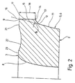
- the side surface 5 or 6 consists of a straight line starting at base area 2 Section 11, which at a kink 12 in a transition surface 13 passes.
- the transition surface 13 ends a bend 14, from where a further surface 15 to leads to the cutting edge 9.
- the area 15 represents the Cutting edge 9 represents the free area.
- the free area is 15 compared to an imaginary extension of the side surface section 11 sublime, in other words the side surfaces 5, 6 contain one of the kinks 12, 14 and the transition surface 13 formed recess, so that above the kink 12 on the imaginary Extension of the side surface portion 11, the illustrated by dashed line 16, one Bar 17 is created.
- the return corresponding to the transition area 13 runs approximately parallel to the cutting edge 9 and the width of the free area 15 by a double arrow 18 is marked and from the cutting edge 9 up to the kink 14 at which the return begins, extends, corresponds approximately to the width of the wear mark in the open space one according to the state of the Technology, i.e. without the indexable insert produced, each based on the desired Machining quality, cutting and feed forces and the material used. Expressed in millimeters, this means a width between O, O 5 mm and 1 mm.
- the depth of the recess measured as that Distance of the kink 14 from the straight line or surface 16, the side surface section 11 at the bend 12 continues steadily, and which is denoted by 19 in FIG is the result of the desired improvement in tool life and the strength to be maintained.
- the depth 19 the return can be between 0.02 and 0.9 mm be.
- an indexable insert 1 is illustrated, at which the clearance angle is O °, i.e. the Indexable insert 1 must be used to achieve a positive Clearance angle are correspondingly negatively embedded.
- the open area 15 is the same width everywhere; it but is also possible, deviating from the form of presentation, the width of the free area 15 along the Varying cutting edge 9 and for example in To provide a different width in the area of the side surface 6 than in the area of the side surface 5.
- the free area 15 is not necessarily flat, it can be the clearance angle of the free area 15 also change along the cutting edge 9, which in particular an advantage when used in end mills is.
- the top 3 of the insert 1 is in designed in a known manner and it is in the figures a common embodiment by way of example only shown. After that starts at the cutting edge 9 a flat chamfer surface 21 which is at a distance of approx. 0.1 mm to 0.2 mm passes into a depression 22. The Trough 22 abuts toward the inside of the top 3 on a flat plateau surface 23 in which the Through hole 8 is located. The chamfer surface 21 together with the trough 22 forms in a known manner the rake face to form the chip.
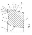
- the indexable insert 1 continue to wear and the contact surface shifts between the insert 1 and the Work up to a dashed line 27 that the transition surface is still at its lower end 13 cuts.
- the slope facing the transition surface 13 has a perpendicular to the base 2, should selected as close as possible to 90 ° in the sense of the invention become.
- the runs Transition surface 13 not parallel to base surface 2, but inclined at an acute angle to breakouts at break points at risk of breakout 12 and 14 to avoid.
- the depth of the recess 19 is directed against it exclusively according to the breaking strength that is necessary is.
- the breaking strength in the Area of the cutting edge 9 is reduced, which is why Cantilever and thus the depth 19 of the bar 17 accordingly must be withdrawn.
- the side surface geometry according to the invention is 4 shows, also on frustoconical round indexable inserts 1 applicable.
- the recess corresponding to the transition area 13 limited open space 15 parallel to the Cutting edge 9 extending around the entire circumference of the Indexable insert 1 around.
- the sidewall structure is otherwise in accordance with the side wall structure 1 to 3 executed.
Landscapes
- Engineering & Computer Science (AREA)
- Mechanical Engineering (AREA)
- Milling Processes (AREA)
- Cutting Tools, Boring Holders, And Turrets (AREA)
- Specific Sealing Or Ventilating Devices For Doors And Windows (AREA)
- Polishing Bodies And Polishing Tools (AREA)
- Auxiliary Devices For Machine Tools (AREA)
- Processing Of Terminals (AREA)
- Turbine Rotor Nozzle Sealing (AREA)
- Magnetically Actuated Valves (AREA)
Claims (7)
- Plaquette de coupe (1) fabriquée par un procédé de frittage, présentant une forme essentiellement de tronc de cône ou de tronc de pyramide,
avec une surface de base (2) essentiellement plane,
avec une face supérieure (3) plane ou structurée distante de la surface de base,
avec un ensemble de parois latérales (4) et au moins une arête de coupe (9),
avec un épaulement (13) faisant partie de l'ensemble de parois latérales (4), qui suit au moins approximativement le contour de l'arête de coupe (9) et forme, à partir de l'arête de coupe (9), un rebord (17) saillant qui porte la face de dépouille (15),
le rebord (17) comprenant une surface de raccordement (13) qui est inclinée suivant un angle aigu aux fins d'éviter des raccordements favorisant les ruptures au niveau des angles,
la largeur (18) de la face de dépouille (15) y compris de la surface de raccordement (13), mesurée dans la direction perpendiculaire à l'arête de coupe (9), correspond sensiblement au repère d'usure admissible de la face de dépouille (15), mesurée dans la même direction,
l'épaulement présente une profondeur (19) qui est comprise entre 0,02 mm et 0,5 mm, des profondeurs supérieures ou égales à 0,4 mm étant exclues,
et l'angle de dépouille est inférieur en valeur à l'angle entre la perpendiculaire à la surface de base et l'ensemble de parois latérales (4). - Plaquette de coupe selon la revendication 1, caractérisée par le fait que la largeur de la face de dépouille (15) est comprise entre 0,05 mm et 1,0 mm.
- Plaquette de coupe selon la revendication 1, caractérisée par le fait que le rebord (17) est présent pratiquement sur tout le pourtour de la plaquette de coupe, le long de l'ensemble de parois latérales (4).
- Plaquette de coupe selon la revendication 1, caractérisée par le fait qu'il s'agit d'une plaquette triangulaire ou polygonale avec des angles au niveau de ses arêtes secondaires et par le fait que le rebord (17) qui forme l'épaulement (13) fait partie d'au moins une arête secondaire.
- Plaquette de coupe selon la revendication 1, caractérisée par le fait que l'angle de dépouille du rebord (17) est égal à 0° ou est supérieur à 0° ou est négatif.
- Plaquette de coupe selon la revendication 1, caractérisée par le fait que l'angle mesuré entre la surface de base (2) et l'ensemble de parois latérales (4) croít ou décroít le long de l'arête de coupe.
- Plaquette de coupe selon la revendication 1, caractérisée par le fait que l'angle de dépouille de la surface de dépouille varie de manière progressive ou par paliers le long de l'arête de coupe.
Applications Claiming Priority (3)
| Application Number | Priority Date | Filing Date | Title |
|---|---|---|---|
| DE4319505A DE4319505C2 (de) | 1993-06-12 | 1993-06-12 | Wendeschneidplatte |
| DE4319505 | 1993-06-12 | ||
| PCT/DE1994/000624 WO1994029055A1 (fr) | 1993-06-12 | 1994-06-04 | Plaquette a jeter |
Publications (3)
| Publication Number | Publication Date |
|---|---|
| EP0702609A1 EP0702609A1 (fr) | 1996-03-27 |
| EP0702609B1 EP0702609B1 (fr) | 1996-12-27 |
| EP0702609B2 true EP0702609B2 (fr) | 2003-03-12 |
Family
ID=6490203
Family Applications (1)
| Application Number | Title | Priority Date | Filing Date |
|---|---|---|---|
| EP94916876A Expired - Lifetime EP0702609B2 (fr) | 1993-06-12 | 1994-06-04 | Plaquette a jeter |
Country Status (7)
| Country | Link |
|---|---|
| US (1) | US5755536A (fr) |
| EP (1) | EP0702609B2 (fr) |
| JP (1) | JP3638603B2 (fr) |
| AT (1) | ATE146710T1 (fr) |
| DE (2) | DE4319505C2 (fr) |
| ES (1) | ES2095768T5 (fr) |
| WO (1) | WO1994029055A1 (fr) |
Families Citing this family (19)
| Publication number | Priority date | Publication date | Assignee | Title |
|---|---|---|---|---|
| DE19528851A1 (de) * | 1995-08-05 | 1997-02-06 | Widia Gmbh | Polygonaler Schneideinsatz |
| DE19742765A1 (de) * | 1997-09-27 | 1999-04-01 | Heller Geb Gmbh Maschf | Schneidplatte, insbesondere Wendeplatte, Verfahren zur Herstellung einer solchen Schneidplatte, mit solchen Schneidplatten ausgestattetes Werkzeug und Verfahren zum Zerspanen eines Werkstückes unter Verwendung einer solchen Schneidplatte oder unter Einsatz eines solchen Werkzeuges |
| DE10040612A1 (de) * | 2000-08-16 | 2002-02-28 | Komet Stahlhalter Werkzeuge | Schneidplatte für drehende Werkzeuge |
| US6508612B1 (en) * | 2000-09-05 | 2003-01-21 | Kennametal Inc. | Milling cutter capable of using inserts of various geometrical shapes |
| DE10207768A1 (de) * | 2001-07-26 | 2003-03-06 | Ceramtec Ag | Schneideinsatz mit Spannmulde und Schneidwerkzeug |
| DE10162132B4 (de) * | 2001-12-18 | 2006-02-23 | Kennametal Inc. | Schneidplatte |
| FR2847838B1 (fr) * | 2002-12-02 | 2006-01-06 | Safety | Plaquette de coupe etagee |
| SE529107C2 (sv) * | 2005-09-28 | 2007-05-02 | Seco Tools Ab | Fräs, fräskropp och vändskär där skäret har formen av en stympad pyramid |
| DE102006020613B4 (de) * | 2006-05-02 | 2009-11-26 | Gottfried Wilhelm Leibniz Universität Hannover | Hartbearbeitungswerkzeug für die spanende Bearbeitung gehärteter Werkzeuge |
| JP5589244B2 (ja) * | 2010-10-06 | 2014-09-17 | 大昭和精機株式会社 | インサート |
| CN107073604B (zh) * | 2014-11-27 | 2019-07-30 | 株式会社泰珂洛 | 切削刀片及刀头更换式旋转切削工具 |
| EP3050655B1 (fr) | 2015-01-30 | 2017-03-22 | Sandvik Intellectual Property AB | Insert de fraisage et outil de fraisage |
| DE102016113348B4 (de) | 2015-11-25 | 2025-06-18 | Gühring KG | Spanabhebendes Werkzeug mit Freiflächenstruktur zur KSS-Lenkung |
| USD832319S1 (en) | 2017-02-15 | 2018-10-30 | Kennametal Inc. | Cutting insert with four-lobed seating area |
| US10406609B2 (en) * | 2017-11-30 | 2019-09-10 | Iscar, Ltd. | Single-sided four-way indexable positive cutting insert and insert mill therefor |
| US10906107B2 (en) | 2018-06-11 | 2021-02-02 | Iscar, Ltd. | Single-sided four-way indexable positive cutting insert and insert mill therefor |
| US11229957B2 (en) * | 2018-10-02 | 2022-01-25 | Jakob Lach Gmbh & Co. Kg | Method for producing a cutting tool for the machining of workpieces and cutting tool |
| DE102020115987A1 (de) | 2019-07-05 | 2021-01-07 | Kennametal India Limited | Beidseitige, polygonale wendeschneidplatte mit abwechselnd konkaven und konvexen schneidkanten |
| DE102019123912A1 (de) | 2019-09-05 | 2021-03-11 | Kennametal Inc. | Schneideinsatz sowie Schneidwerkzeug |
Family Cites Families (9)
| Publication number | Priority date | Publication date | Assignee | Title |
|---|---|---|---|---|
| DE877531C (de) * | 1951-05-03 | 1953-05-26 | Eisen & Stahlind Ag | Schneidwerkzeug, insbesondere Walzenfraeser mit eingesetzter Hartmetallschneide |
| US4449864A (en) * | 1981-12-07 | 1984-05-22 | Sazzadul Haque | Consumable self-regenerative ledge cutting insert |
| US4588332A (en) * | 1982-11-03 | 1986-05-13 | General Electric Company | Self-sharpening tool constructions having chip-grooves |
| JPS60175516U (ja) * | 1984-04-28 | 1985-11-20 | 三菱マテリアル株式会社 | 転削工具用スロ−アウエイチツプ |
| US4627317A (en) * | 1984-06-25 | 1986-12-09 | General Electric Company | Consumable ceramic ledge tool |
| SE456564B (sv) * | 1986-06-04 | 1988-10-17 | Ola Svanstrom | Anordning for avkenning av fasforslitning vid skerverktyg |
| GB8920227D0 (en) * | 1989-09-07 | 1989-10-18 | Iscar Hartmetall | A cutting insert |
| EP0458003B1 (fr) * | 1990-05-22 | 1995-02-15 | Seco Tools Ab | Plaquette de coupe |
| SE500703C2 (sv) * | 1993-01-27 | 1994-08-15 | Sandvik Ab | Skär med ett urtag i anslutning till en vriden släppningsyta |
-
1993
- 1993-06-12 DE DE4319505A patent/DE4319505C2/de not_active Expired - Lifetime
-
1994
- 1994-06-04 WO PCT/DE1994/000624 patent/WO1994029055A1/fr not_active Ceased
- 1994-06-04 JP JP50118295A patent/JP3638603B2/ja not_active Expired - Fee Related
- 1994-06-04 ES ES94916876T patent/ES2095768T5/es not_active Expired - Lifetime
- 1994-06-04 US US08/564,329 patent/US5755536A/en not_active Expired - Lifetime
- 1994-06-04 EP EP94916876A patent/EP0702609B2/fr not_active Expired - Lifetime
- 1994-06-04 AT AT94916876T patent/ATE146710T1/de not_active IP Right Cessation
- 1994-06-04 DE DE59401415T patent/DE59401415D1/de not_active Expired - Lifetime
Also Published As
| Publication number | Publication date |
|---|---|
| US5755536A (en) | 1998-05-26 |
| JP3638603B2 (ja) | 2005-04-13 |
| DE59401415D1 (de) | 1997-02-06 |
| WO1994029055A1 (fr) | 1994-12-22 |
| DE4319505A1 (de) | 1994-12-15 |
| ES2095768T5 (es) | 2003-11-01 |
| ATE146710T1 (de) | 1997-01-15 |
| EP0702609A1 (fr) | 1996-03-27 |
| EP0702609B1 (fr) | 1996-12-27 |
| DE4319505C2 (de) | 1996-02-15 |
| JPH09502395A (ja) | 1997-03-11 |
| ES2095768T3 (es) | 1997-02-16 |
Similar Documents
| Publication | Publication Date | Title |
|---|---|---|
| EP0702609B2 (fr) | Plaquette a jeter | |
| DE69604484T2 (de) | Schraubenförmiger schneideinsatz mit versetzten schneidkanten | |
| DE60113369T2 (de) | Schneidwerkzeug | |
| EP2403673B2 (fr) | Fraise à queue | |
| DE69409365T2 (de) | Schneideinsatz mit spiralförmiger spanfläche | |
| EP0781182B1 (fr) | Plaquette de coupe | |
| DE10317760B4 (de) | Fräswerkzeug und Schneidplatte für ein solches | |
| DE69921917T2 (de) | Indexierbarer Schneideinsatz für drehende Fräsen | |
| DE112008001089B4 (de) | Schneideinsatz und Schneidwerkzeug sowie Schneidverfahren, das diese verwendet | |
| EP1184116B1 (fr) | Outil de fraisage et de perçage | |
| EP3107676B1 (fr) | Plaquette de coupe indexable et fraise | |
| DE60204559T2 (de) | Bohreinsatzgeometrie mit spanspaltender kerbe | |
| EP1486279A1 (fr) | Plaquette de coupe pour tourner et fraiser | |
| EP2155425A1 (fr) | Plaquette de coupe à facette double paroi stabilisatrice | |
| EP0073926A1 (fr) | Outil de coupe, en particulier plaquette amovible | |
| DE10342060B4 (de) | Einwegspitze | |
| DE60021529T2 (de) | Schneideinsatz für drehbearbeitung | |
| DE29810969U1 (de) | Schneideinsatz, Schneidwerkzeug zur spanenden Bearbeitung, insbesondere von rotationssymmetrischen Werkstückflächen | |
| AT14072U1 (de) | Doppelseitiger Frässchneideinsatz und Fräswerkzeug | |
| WO1996035538A1 (fr) | Plaquette et outil de fraisage | |
| EP0083357A1 (fr) | Plaquette de coupe outil d'usinage par enlevement de copeaux. | |
| EP3996861B1 (fr) | Plaquette de coupe double face pour fraisage | |
| EP0631834B1 (fr) | Plaquette de coupe pour alésoir | |
| DE10338784A1 (de) | Schneidplatte für einen Fingerfräser | |
| EP1283083B1 (fr) | Plaquette de fraisage |
Legal Events
| Date | Code | Title | Description |
|---|---|---|---|
| PUAI | Public reference made under article 153(3) epc to a published international application that has entered the european phase |
Free format text: ORIGINAL CODE: 0009012 |
|
| 17P | Request for examination filed |
Effective date: 19950217 |
|
| AK | Designated contracting states |
Kind code of ref document: A1 Designated state(s): AT BE CH DE ES FR GB IT LI LU NL SE |
|
| 17Q | First examination report despatched |
Effective date: 19960322 |
|
| GRAG | Despatch of communication of intention to grant |
Free format text: ORIGINAL CODE: EPIDOS AGRA |
|
| GRAH | Despatch of communication of intention to grant a patent |
Free format text: ORIGINAL CODE: EPIDOS IGRA |
|
| GRAH | Despatch of communication of intention to grant a patent |
Free format text: ORIGINAL CODE: EPIDOS IGRA |
|
| GRAA | (expected) grant |
Free format text: ORIGINAL CODE: 0009210 |
|
| AK | Designated contracting states |
Kind code of ref document: B1 Designated state(s): AT BE CH DE ES FR GB IT LI LU NL SE |
|
| PG25 | Lapsed in a contracting state [announced via postgrant information from national office to epo] |
Ref country code: NL Free format text: LAPSE BECAUSE OF FAILURE TO SUBMIT A TRANSLATION OF THE DESCRIPTION OR TO PAY THE FEE WITHIN THE PRESCRIBED TIME-LIMIT Effective date: 19961227 |
|
| REF | Corresponds to: |
Ref document number: 146710 Country of ref document: AT Date of ref document: 19970115 Kind code of ref document: T |
|
| REG | Reference to a national code |
Ref country code: CH Ref legal event code: NV Representative=s name: KIRKER & CIE SA |
|
| ET | Fr: translation filed | ||
| ITF | It: translation for a ep patent filed | ||
| REF | Corresponds to: |
Ref document number: 59401415 Country of ref document: DE Date of ref document: 19970206 |
|
| REG | Reference to a national code |
Ref country code: ES Ref legal event code: FG2A Ref document number: 2095768 Country of ref document: ES Kind code of ref document: T3 |
|
| GBT | Gb: translation of ep patent filed (gb section 77(6)(a)/1977) |
Effective date: 19970130 |
|
| PLBI | Opposition filed |
Free format text: ORIGINAL CODE: 0009260 |
|
| PLBQ | Unpublished change to opponent data |
Free format text: ORIGINAL CODE: EPIDOS OPPO |
|
| PLBI | Opposition filed |
Free format text: ORIGINAL CODE: 0009260 |
|
| PLBF | Reply of patent proprietor to notice(s) of opposition |
Free format text: ORIGINAL CODE: EPIDOS OBSO |
|
| 26 | Opposition filed |
Opponent name: WIDIA GMBH Effective date: 19970918 |
|
| 26 | Opposition filed |
Opponent name: PLANSEE TIZIT GMBH Effective date: 19970927 Opponent name: WIDIA GMBH Effective date: 19970918 |
|
| NLR1 | Nl: opposition has been filed with the epo |
Opponent name: WIDIA GMBH |
|
| NLR1 | Nl: opposition has been filed with the epo |
Opponent name: PLANSEE TIZIT GMBH Opponent name: WIDIA GMBH |
|
| PLBF | Reply of patent proprietor to notice(s) of opposition |
Free format text: ORIGINAL CODE: EPIDOS OBSO |
|
| PLBF | Reply of patent proprietor to notice(s) of opposition |
Free format text: ORIGINAL CODE: EPIDOS OBSO |
|
| PLAB | Opposition data, opponent's data or that of the opponent's representative modified |
Free format text: ORIGINAL CODE: 0009299OPPO |
|
| R26 | Opposition filed (corrected) |
Opponent name: WIDIA GMBH * 19970927 PLANSEE TIZIT AG Effective date: 19970918 |
|
| RDAH | Patent revoked |
Free format text: ORIGINAL CODE: EPIDOS REVO |
|
| APAC | Appeal dossier modified |
Free format text: ORIGINAL CODE: EPIDOS NOAPO |
|
| APAE | Appeal reference modified |
Free format text: ORIGINAL CODE: EPIDOS REFNO |
|
| APAC | Appeal dossier modified |
Free format text: ORIGINAL CODE: EPIDOS NOAPO |
|
| REG | Reference to a national code |
Ref country code: GB Ref legal event code: IF02 |
|
| PGFP | Annual fee paid to national office [announced via postgrant information from national office to epo] |
Ref country code: CH Payment date: 20020517 Year of fee payment: 9 |
|
| PGFP | Annual fee paid to national office [announced via postgrant information from national office to epo] |
Ref country code: NL Payment date: 20020531 Year of fee payment: 9 |
|
| PGFP | Annual fee paid to national office [announced via postgrant information from national office to epo] |
Ref country code: LU Payment date: 20020606 Year of fee payment: 9 |
|
| PGFP | Annual fee paid to national office [announced via postgrant information from national office to epo] |
Ref country code: BE Payment date: 20020612 Year of fee payment: 9 |
|
| APAC | Appeal dossier modified |
Free format text: ORIGINAL CODE: EPIDOS NOAPO |
|
| PLAW | Interlocutory decision in opposition |
Free format text: ORIGINAL CODE: EPIDOS IDOP |
|
| PUAH | Patent maintained in amended form |
Free format text: ORIGINAL CODE: 0009272 |
|
| STAA | Information on the status of an ep patent application or granted ep patent |
Free format text: STATUS: PATENT MAINTAINED AS AMENDED |
|
| 27A | Patent maintained in amended form |
Effective date: 20030312 |
|
| AK | Designated contracting states |
Designated state(s): AT BE CH DE ES FR GB IT LI LU NL SE |
|
| REG | Reference to a national code |
Ref country code: CH Ref legal event code: AEN Free format text: AUFRECHTERHALTUNG DES PATENTES IN GEAENDERTER FORM |
|
| NLR2 | Nl: decision of opposition |
Effective date: 20030312 |
|
| PG25 | Lapsed in a contracting state [announced via postgrant information from national office to epo] |
Ref country code: LU Free format text: LAPSE BECAUSE OF NON-PAYMENT OF DUE FEES Effective date: 20030604 |
|
| REG | Reference to a national code |
Ref country code: SE Ref legal event code: RPEO |
|
| PG25 | Lapsed in a contracting state [announced via postgrant information from national office to epo] |
Ref country code: LI Free format text: LAPSE BECAUSE OF NON-PAYMENT OF DUE FEES Effective date: 20030630 Ref country code: CH Free format text: LAPSE BECAUSE OF NON-PAYMENT OF DUE FEES Effective date: 20030630 Ref country code: BE Free format text: LAPSE BECAUSE OF NON-PAYMENT OF DUE FEES Effective date: 20030630 |
|
| GBTA | Gb: translation of amended ep patent filed (gb section 77(6)(b)/1977) | ||
| NLV1 | Nl: lapsed or annulled due to failure to fulfill the requirements of art. 29p and 29m of the patents act | ||
| REG | Reference to a national code |
Ref country code: ES Ref legal event code: DC2A Date of ref document: 20030519 Kind code of ref document: T5 |
|
| ET3 | Fr: translation filed ** decision concerning opposition | ||
| BERE | Be: lapsed |
Owner name: *WALTER A.G. Effective date: 20030630 |
|
| REG | Reference to a national code |
Ref country code: CH Ref legal event code: PL |
|
| APAH | Appeal reference modified |
Free format text: ORIGINAL CODE: EPIDOSCREFNO |
|
| PGFP | Annual fee paid to national office [announced via postgrant information from national office to epo] |
Ref country code: ES Payment date: 20090623 Year of fee payment: 16 |
|
| PGFP | Annual fee paid to national office [announced via postgrant information from national office to epo] |
Ref country code: SE Payment date: 20090612 Year of fee payment: 16 Ref country code: IT Payment date: 20090623 Year of fee payment: 16 Ref country code: FR Payment date: 20090615 Year of fee payment: 16 Ref country code: AT Payment date: 20090615 Year of fee payment: 16 |
|
| PGFP | Annual fee paid to national office [announced via postgrant information from national office to epo] |
Ref country code: GB Payment date: 20090618 Year of fee payment: 16 |
|
| EUG | Se: european patent has lapsed | ||
| GBPC | Gb: european patent ceased through non-payment of renewal fee |
Effective date: 20100604 |
|
| REG | Reference to a national code |
Ref country code: FR Ref legal event code: ST Effective date: 20110228 |
|
| PG25 | Lapsed in a contracting state [announced via postgrant information from national office to epo] |
Ref country code: IT Free format text: LAPSE BECAUSE OF NON-PAYMENT OF DUE FEES Effective date: 20100604 |
|
| PG25 | Lapsed in a contracting state [announced via postgrant information from national office to epo] |
Ref country code: AT Free format text: LAPSE BECAUSE OF NON-PAYMENT OF DUE FEES Effective date: 20100604 Ref country code: FR Free format text: LAPSE BECAUSE OF NON-PAYMENT OF DUE FEES Effective date: 20100630 |
|
| REG | Reference to a national code |
Ref country code: ES Ref legal event code: FD2A Effective date: 20110715 |
|
| PG25 | Lapsed in a contracting state [announced via postgrant information from national office to epo] |
Ref country code: GB Free format text: LAPSE BECAUSE OF NON-PAYMENT OF DUE FEES Effective date: 20100604 Ref country code: ES Free format text: LAPSE BECAUSE OF NON-PAYMENT OF DUE FEES Effective date: 20110705 |
|
| PG25 | Lapsed in a contracting state [announced via postgrant information from national office to epo] |
Ref country code: ES Free format text: LAPSE BECAUSE OF NON-PAYMENT OF DUE FEES Effective date: 20100605 |
|
| PG25 | Lapsed in a contracting state [announced via postgrant information from national office to epo] |
Ref country code: SE Free format text: LAPSE BECAUSE OF NON-PAYMENT OF DUE FEES Effective date: 20100605 |
|
| PGFP | Annual fee paid to national office [announced via postgrant information from national office to epo] |
Ref country code: DE Payment date: 20130630 Year of fee payment: 20 |
|
| REG | Reference to a national code |
Ref country code: DE Ref legal event code: R071 Ref document number: 59401415 Country of ref document: DE |
|
| PG25 | Lapsed in a contracting state [announced via postgrant information from national office to epo] |
Ref country code: DE Free format text: LAPSE BECAUSE OF EXPIRATION OF PROTECTION Effective date: 20140605 |