EP0702746B1 - Systeme de remplacement in situ de moyens coupants pour un trepan de sondage - Google Patents
Systeme de remplacement in situ de moyens coupants pour un trepan de sondage Download PDFInfo
- Publication number
- EP0702746B1 EP0702746B1 EP94918244A EP94918244A EP0702746B1 EP 0702746 B1 EP0702746 B1 EP 0702746B1 EP 94918244 A EP94918244 A EP 94918244A EP 94918244 A EP94918244 A EP 94918244A EP 0702746 B1 EP0702746 B1 EP 0702746B1
- Authority
- EP
- European Patent Office
- Prior art keywords
- segments
- tool
- insert
- installation
- drill
- Prior art date
- Legal status (The legal status is an assumption and is not a legal conclusion. Google has not performed a legal analysis and makes no representation as to the accuracy of the status listed.)
- Expired - Lifetime
Links
Images







Classifications
-
- E—FIXED CONSTRUCTIONS
- E21—EARTH OR ROCK DRILLING; MINING
- E21B—EARTH OR ROCK DRILLING; OBTAINING OIL, GAS, WATER, SOLUBLE OR MELTABLE MATERIALS OR A SLURRY OF MINERALS FROM WELLS
- E21B23/00—Apparatus for displacing, setting, locking, releasing or removing tools, packers or the like in boreholes or wells
- E21B23/03—Apparatus for displacing, setting, locking, releasing or removing tools, packers or the like in boreholes or wells for setting the tools into, or removing the tools from, laterally offset landing nipples or pockets
-
- E—FIXED CONSTRUCTIONS
- E21—EARTH OR ROCK DRILLING; MINING
- E21B—EARTH OR ROCK DRILLING; OBTAINING OIL, GAS, WATER, SOLUBLE OR MELTABLE MATERIALS OR A SLURRY OF MINERALS FROM WELLS
- E21B10/00—Drill bits
- E21B10/64—Drill bits characterised by the whole or part thereof being insertable into or removable from the borehole without withdrawing the drilling pipe
- E21B10/66—Drill bits characterised by the whole or part thereof being insertable into or removable from the borehole without withdrawing the drilling pipe the cutting element movable through the drilling pipe and laterally shiftable
-
- E—FIXED CONSTRUCTIONS
- E21—EARTH OR ROCK DRILLING; MINING
- E21B—EARTH OR ROCK DRILLING; OBTAINING OIL, GAS, WATER, SOLUBLE OR MELTABLE MATERIALS OR A SLURRY OF MINERALS FROM WELLS
- E21B10/00—Drill bits
- E21B10/02—Core bits
-
- E—FIXED CONSTRUCTIONS
- E21—EARTH OR ROCK DRILLING; MINING
- E21B—EARTH OR ROCK DRILLING; OBTAINING OIL, GAS, WATER, SOLUBLE OR MELTABLE MATERIALS OR A SLURRY OF MINERALS FROM WELLS
- E21B25/00—Apparatus for obtaining or removing undisturbed cores, e.g. core barrels or core extractors
- E21B25/02—Apparatus for obtaining or removing undisturbed cores, e.g. core barrels or core extractors the core receiver being insertable into, or removable from, the borehole without withdrawing the drilling pipe
Definitions
- This invention relates to a system for in situ replacement of cutting means for a ground drill, and in particular, though not exclusively, to a system for the in situ replacement of drill bits and/or reamers of core sampling drills.
- drill bit In ground drilling it is customary to detachably fix a drill bit to a lower end of a drill string of a ground drill and rotate the drill string to effect drilling of a hole in the ground by the drill bit.
- a reamer is usually connected between the lower end of the drill string and the drill bit to ream the circumferential wall of a hole being drilled.
- the drill string is formed by screwing individual drill rods together. Drill rods usually come in fixed lengths of 1.5, 3 or 6 metres. As the drill progresses into the ground additional drill rods are screwed into the upper end drill string.
- EP-A-208532, EP-A-429649, and US-A-2982366 all disclose retractable drill bit systems.
- a system for in situ replacement of cutting means of a ground drill where the cutting means is composed of a plurality of segments said system including:
- said tool comprises installation latching means and retrieval latching means for engaging said insert, said installation means being operable and said retrieval latching means being inoperable when said tool is in said installation mode and both said installation and said retrieval latching means being operable when said tool is in said retrieval mode, wherein, said installation means can engage said insert when said tool is lowered into said drill and said retrieval latching means can engage said sleeve when said tool is pulled upwardly a first distance so as to pull said insert upwardly said first distance, said retrieval latching means being disengaged automatically from said insert upon pulling said tool upwardly beyond said first distance.
- said tool includes mode selecting means for switching said tool between said installation and retrieval modes, said mode switching means comprising a selector sleeve slidably and rotatably mounted on a body portion of said tool, and provided with installation apertures and retrieval apertures through which said installation latching means and said retrieval latching means can protrude respectively, wherein said selector sleeve can be rotated from a first position corresponding to the installation mode in which said installation apertures over-lie said installation latching means and said retrieval apertures are radially offset relative to said retrieval latching means and, a second position corresponding to said retrieval mode in which said installation apertures and said retrieval apertures over-lie said installation latching means and said retrieval latching mean respectively.
- said installation latching means engages said insert by way of abutment with one or more abutment surfaces formed near an upper end of said insert.
- said upper end of said insert is profiled in a manner so that when said installation latching means contacts said upper end, said tool can be rotated about its longitudinal axis to align said tool, insert and segments so that said segments can be installed in or retrieved from between said insert and said member.
- said insert is provided with a first detent for engaging said retrieval latching means and said system further includes means for disengaging said retrieval latching means from said first detent when said tool is pulled upwardly beyond said first distance.
- said disengaging means comprises a tapered surface for compressing said retrieval latching means.
- said tool comprises carrier means onto which said segments can be loaded for carrying said segments to and from said member, and wherein said tool is operable to cause said segments to slide relative to said tool body when said tool engages said insert whereby an upper end of said segments can extend laterally of said tool to engage said seating means and said insert.
- said carrier means comprises a cradle about which said segments are radially spaced, said cradle being slidable relative to a portion of said tool when said tool is in said installation mode and said tool engages said insert, whereby upon relative sliding movement of said cradle and said portion of said tool, said upper end of the segments extend laterally of said tool for engagement by said seating means and said insert.
- said system further comprises an elastic band surrounding said segments for retaining said segments on said tool, said elastic band acting to bias said segments toward a central longitudinal axis of said member when said segments are retained in said cutting position whereby, during retrieval of said segments, said elastic band assists in collapsing said segments onto said tool.
- said cradle comprises an elongate shank extending from a lower tapered end of said body portion of said tool and being slidably housed within a bore in said body portion, and biasing means acting to retract said shank into said bore, wherein, in said installation mode and prior to engagement of said tool with said insert, said biasing means is held in compression and said shank extends from said bore so that the upper ends of said segments rest on said tapered end and upon engagement of said tool with said insert, said biasing means is released from compression thereby retracting said shank into said bore so that the upper ends of said segments slide along said tapered end to extend laterally of said tool.
- said selector sleeve operates a second detent means for holding said biasing means in compression and wherein said selector sleeve is coupled to said installation latching means so that when said installation latching means engages said insert said selector sleeve slides relative to said tool body to release said second detent means thereby allowing expansion of said biasing means and retraction of said shank into said bore.
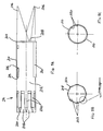
- Figure 1 illustrates a first embodiment of a system 10 for the in situ replacement of cutting means in the form of a drill bit of a ground drill 12.
- the drill 12 is composed of a plurality of interconnected drill rods 14 which together form a drill string.
- a standard reamer 16 for reaming the circumferential wall of a hole being drilled is screwed to the free end of the lowest rod 14.
- the system 10 comprises a number of separate but interactive components these including a tubular member taking the form of a drive sub 18 which is adapted for connection to a lower end of the drill 12, an installation and retrieval tool 20 dimensioned to travel through the drill 12 for carrying drill bit segments 22 (refer Figs. 7a, 7b, and 9) to and from the drive sub 18 and, a substantially cylindrical insert 24 which is slidably retained within the member 18 between an installation position in which the insert retains the bit segments 22 in the drive sub 18 and a retrieval position in which the insert 24 is retracted to allow the bit segments 22 to collapse onto the tool 20 for withdrawal from the drill 12.
- a tubular member taking the form of a drive sub 18 which is adapted for connection to a lower end of the drill 12, an installation and retrieval tool 20 dimensioned to travel through the drill 12 for carrying drill bit segments 22 (refer Figs. 7a, 7b, and 9) to and from the drive sub 18 and, a substantially cylindrical insert 24 which is slidably retained within the member 18
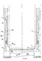
- the inner circumferential wall 26 at a lower end 28 of the drive sub 18 is provided with seating means 30 for seating the bit segments 22.
- the seating means 30 includes a land 32 extending circumferentially about the inner surface 26 followed, in the downstream direction, with a series of tapered and flat surfaces and recess 58 formed on the lowermost one of those surfaces.
- the land 32 is followed by the following sequence of surfaces in the down stream direction: surface 34 tapering away from a central longitudinal axis 36 of the drive sub 18; surface 38 extending parallel with axis 36; surface 40 tapering toward axis 36; surface 42 tapering away from axis 36; surface 44 extending parallel to axis 36; surface 46 tapering toward axis 36; and surface 48 tapering away from axis 36 and extending to the longitudinal extremity 50 of the drive sub 18.
- Contiguous with surface 48 is a surface 52 tapering away from both axis 36 and extremity 50 and which leads to outer circumferential surface 54 of the drive sub 18.
- a plurality of drive lugs 56 are provided on surface 46. Adjacent drive lugs 56 define the recesses 58 in which a lower end of the bit segments 22 are held during drilling. As is most evident from Figure 6b, the width of the drive lugs 56 reduces in the radial direction toward axis 36.
- a pair of opposed slots 60 extending parallel to axis 36 are machined in wall 26 inboard of the ends of the drive sub 18.
- a locking clip 62 (refer Figures 8a and 8b) is inserted into an upper end 64 of each slot 60.
- a lower end of each locking clip is formed with a surface 65 tapering toward the inner wall 26 and a spring clip 66 attached near an upper end of the clip on a surface opposite the inner wall 26.
- bit segments 22 are configured for mating with the seating means 30 of the drive sub 18.
- the bit segments comprise a shank 68 and a crown 70 formed at a lower end of the shank 68 for engaging and cutting the ground.
- the crown 70 typically comprises a matrix of diamonds and metal. In use, as ground engaging face 72 of the crown wears away fresh diamonds are exposed to facilitate cutting.
- Side 74 (shown uppermost in Figure 7b) of the bit segments 22 faces the inner surface 26 of the drive sub 18.
- the side 74 of shank 68 comprises the following sequence of surfaces starting from crown 70 (the axis 36 is shown in phantom for convenient reference in Figure 7a); surface 76 tapering toward axis 36; surface 77 extending parallel to axis 36; surface 78 tapering away from axis 36; surface 80 tapering toward axis 36; level surface 82 extending parallel to axis 36; surface 84 tapering away from axis 36; surface 86 tapering toward axis 36; surface 88 extending parallel to axis 36.
- Surface 88 is followed by an abrupt step 90 which leads to surface 92 tapering toward axis 36 and extending to extremity 94 of the shank 68.
- Opposite side 96 of shank 68 comprises the following sequence of surfaces in the direction from extremity 94 to crown 70: surface 98 tapering toward axis 36; level surface 100 extending parallel to axis 36; surface 102 tapering toward axis 36; and level surface 104 extending parallel to axis 36.
- the crown 70 is in the shape of a sector of an annulus and formed with inner and outer arcuate faces 106 and 108 respectively, with the length of face 108 being greater than that of face 106.
- the face of the crown 70 opposite cutting face 72 is provided with the following sequence of surfaces in the direction from outer face 108 to inner face 106: surface 110 extending parallel to cutting face 72; surface 112 inclined toward cutting face 72 and terminating adjacent surface 76 of shank 68; and surface 114 tapering away from cutting face 72 and terminating at arcuate face 106.
- Surfaces 112 and 76 form a V-shaped recess 116 which can engage the surfaces 48 and 52 of the drive sub 18 (as seen in Figure 10).
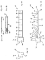
- a tool 20 comprises a main body portion 118 upon which a selector sleeve 120 is slidably and rotatably retained.
- An upper end 122 of body 118 is provided with a screw thread for attaching a standard wire line adaptor 124.
- a pair of opposing longitudinal grooves (not shown) are machined in body 118 at end 122 for slidably retaining a ring 126.
- the ring is provided on its inner circumferential surface with a pair of protrusions (not shown) which ride in the grooves to allow the ring 126 to slide longitudinally of the body 118.
- a spring 128 retained between the wire line adaptor 124 and ring 126 acts to bias the ring 126 and sleeve 120 away from end 122.
- a protrusion 130 is formed on an end of ring 126 adjacent the sleeve 120 for engagement in one of the two mode selector recesses 132, 134 cut in an adjacent end of the sleeve 120.
- Body 118 is provided with an internal cavity 136 which houses a pair of installation latch dogs 138.
- Pin 140 extends through one end of both latch dogs 138 and couples the body 118 to the sleeve 120.
- the pin 140 resides in a longitudinal slot (not shown) formed in the body 118 and a transversely extending slot 142 formed in the sleeve 120.
- Each end of pin 140 sits on a lip 143 formed about the periphery of slots 142. This provides a connection between body 118 and sleeve 120 where the sleeve can slide longitudinally and rotate relative to the body 118.
- a second pin 144 extends parallel to pin 140 and resides in a longitudinal slot 148 formed in the body 118.
- Spring 150 connects opposite ends of latch dogs 138 to the pin 144. The spring 150 biases the latch dogs 138 so as to extend laterally of body 118 and through apertures or slots 139 (refer Figs. 4A, 4D) cut in sleeve 120.
- Each latch dog 138 is provided with a bearing face 152 for abutment with the insert 24.
- a pair of retrieval latch dogs 154 similar to the insertion latch dogs 138 is also provided in the tool 20 on a side of the latch dogs 138 opposite end 122.
- the retrieval latch dogs 154 are located in a plane disposed perpendicular to that containing the insertion latch dogs 138.
- the retrieval latch dogs are orientated in an opposite sense to the insertion latch dogs 138. That is, ends 156 of retrieval latch dogs 154 are biased by a spring (not shown) to extend laterally of the body 118 and through apertures or slots 155 (refer Figures 4a, 4e) cut in sleeve 120 with opposite ends 158 being held by a pin 160 extending through the body 118.
- Bearing faces 162 are formed at ends 156 of the retrieval latch dogs 154 for engaging the insert 24.
- the installation latch dog slots 139 are wider than the retrieval latch dog slots 155.
- a rectangular cavity 164 is formed in the body 118 adjacent the retrieval latch dogs 154. Extending longitudinally of one end 166 of the cavity 164 is a hole 168 which communicates with cylindrical recess 170. Recess 170 extends through a frusto-conical shaped end 172 of the body 118. The cavity 164, hole 168 and recess 170 collectively form a slideway 174 for a cradle 176 upon which the bit segments 22 are attained.
- the cradle 176 comprises a central bar 178 from which coaxially extends at one end a threaded stem 180 and terminates at an opposite end in a stop 182.
- the stem 180 extends through recess 170 and hole 168 into cavity 164.
- the end of the bar 178 adjacent the stem 180 is slidably received in recess 170.
- a spring 184 is retained on the stem 180 between a tension adjustment nut 186 screwed onto the stem 180 and end 166 of the cavity 164.
- Opposite ends 188 and 190 of the nut 186, are tapered or bevelled so as to reduce in thickness radially away from the centre of the nut 168.
- a pair of locking pins reside in respective recesses 192 formed in the body 118.
- the pins are retained within their respective recesses 192 by the sleeve 120 and have an end which can be selectively extended into and retracted from the recess 164 by virtue of relative movement of the sleeve 120.
- an inner circumferential wall 194 of the sleeve 120 is provided with a circumferential groove 196.
- the ends of the pins are held to extend into the cavity 164 by abutment of the pins with wall 194 when the sleeve 120 is positioned so that the groove 196 does not overlie the recesses 192. Under this condition, the pins abut against nut 186 maintaining the spring 184 in compression.
- each bit segment 22 When loading the tool 20 to install the bit segments 22, the segments are disposed radially about the bar 178 with crowns 70 abuting the stop 182. Surface 98 of each bit segment 22 rests on the large diameter end of frusto-conical end 172 for the body 118. An elastic band 198 encircles the bit segments 22 about respective surfaces 82 to hold the bit segments onto the cradle 176.
- a plurality of ridges 200 are provided on the outside surface of sleeve 120 extending parallel to the length of the sleeve 120.
- the ridges 200 are evenly spaced, with adjacent ridges defining shallow channels 202 through which a fluid can flow when the tool 20 is lowered through the drill 12.
- Insert 24 (refer Figs. 5a-5c) is provided in the system 10 for expanding the bit segments 22 against the bias of elastic band 198 and locating the bit segments 22 into a cutting or drilling position against the inner surface of drive sub 18.
- the insert 24 is in the form of a cylindrical tube having a pair of opposing peaks 206 extending from an upstream end 204. The sides of each peak slope sharply in the downstream direction and lead to flats 208 which separate the peaks 206.
- a pair of longitudinally extending rails 210 protrude from the outer circumferential surface 212 of insert 24. The rails 210 ride in the slots 60 in the drive sub 18.
- a pair of opposed detents in the form of longitudinally extending slots 214 (only one shown) are cut into the insert 24 for engaging the retrieval latch dogs 154.
- An upstream end of each slot 214 is bevelled so as to slope toward an inner surface of the insert 214 in the upstream direction.
- the end of the sleeve 24 opposite peaks 206 is provided with a plurality of longitudinally extending keyways 218. Adjacent keyways 218 are spaced apart by lugs 220. Waterways 222 are machined along the length of the inner surface of insert 24. The waterways provide a flow path for water used in bit cooling, lubrication and flushing.
- a tool 20' for replacing reamer segments (refer Figs. 13 and 14) is structurally and functionally equivalent to the tool 20 used for replacement of drill bit segments 22. Accordingly, the reference numbers used in relation to the description of the tool 20 are also employed to denote similar features in the tool 20'.
- a wireline adaptor 124' is screwed onto upper end 122 of the tool 20'.
- Spring 128' interposes the wireline adaptor 124' and ring 126'.
- the ring 126' is able to slide longitudinally of the tool 20' as provided with a protrusion 130 for engaging recesses (not shown) cut in an upper end of sleeve 120'.
- Installation and retrieval latch dogs 138' and 154' are identical to those of tool 20.
- the essential differences between tool 20' and tool 20 are that the cradle 176' comprises a plurality of cut-outs 227 formed radially about a lower end of body 118'. An upper end of each cut-out is provided with a ramp 228 which leads to the outer surface of body 118'.
- sleeve 120' is provided with a plurality of apertures 230 which overlie the cut-outs 227.
- a radially inwardly directed lip 232 is provided at the lower end of each aperture 230.
- a further difference between tools 20 and 20' is the length of the slots in which the pins of the installation and retrieval latch dogs are retained. Specifically, the slots in tool 20' (see for example slot 148') are much longer than those of the corresponding slots in tool 20.
- a standard overshot attachment 234 is connected to the lower end of tool 20' for connection with the wireline adaptor 124 of tool 20. This connection allows the tools 20 and 20' to rotate relative to each other.
- Reamer segments 226 are retained in cut-outs 227 when being installed in or retrieved from the drill 12.
- Reamer segments 226 are in the shape of a rectangular prism having inclined sides.
- Each segment 226 is mounted on a rectangular plate 236.
- Upstanding lips 238 and 240 extend across the upstream and downstream ends of the plate 326 respectively. Both lip 240 and the upstream end of the plate 236 are bevelled so as to converge toward each other in the upstream direction.
- the segments 226 are retained in cut-outs 227 by rubber bands 242 and 244 which encircle plates 236 adjacent the ends of the corresponding segments 226.
- Auxiliary drive sub 18' is provided with seating means comprising a land 32' protruding inwardly from an inner circumferential wall of drive sub 18' and cut-outs 246 (only one shown) having bevelled edges 248 for seating the bit segments 226.
- a recess 250 is cut into the inner surface of the drive sub 18 adjacent the downstream end of each cut-out 246 for accommodating the lips 238.
- Auxiliary insert 24' is retained with auxiliary drive sub 18 for selectively holding the segments 226 in a cutting position and releasing the segments 226 for replacement.
- Insert 24' is essentially the same as insert 24 with the exception that it does not include the keyways 218 and lugs 220 of insert 24.
- Tool 20' is used to slide the insert 24' between an installation position in which the insert 24' locates and retains the segments 226 in the cutting position and, a retrieval position in which the insert 24' is retracted to release the segments so that they can collapse back onto the tool 20' by action of the elastic bands 242 and 244.
- the ground drill 12 is in this embodiment a core sampling drill such as for example, of the type manufactured by LONGYEAR.
- Core sampling drills typically include a landing ring 252 retained in a lower end of the drill 12.
- the landing ring 252 is used to halt the passage of a conventional core sample barrel 254 (refer Figures 10 and 11).
- the top of the core sample barrel 254 rests on the landing ring 252 preventing the core sample barrel 254 from falling out of the drill 12.
- the core sample barrel 254 is used to collect and retain a core sample of the ground being drilled. Once the core sample barrel is filled, drilling is stopped, the drill lifted from the bottom of the hole being drilled to break the core sample, then the core sample barrel lifted up through the drill 12 by a wire line 256.
- the drive sub 18 is screwed onto the reamer 16 of a standard core sampling drill.
- Tool 20 is set to the installation mode by turning sleeve 120 relative to ring 126 so that the protrusion 130 engages installation mode selector recess 132.
- Cradle 176 is extended from body 118 compressing the spring 184 which is held in compression by locking pins (not shown) having ends extending into the cavity 164.
- the installation latch dogs 138 extend laterally from slots 139 in the sleeve 120.
- the retrieval latch dogs 154 are not aligned with slots 155 and are therefore held in a compressed state within the confines of sleeve 120.
- Bit segments 22 are loaded onto the cradle 176 and held in place by elastic band 198 which contacts the surface 82 of each bit segment 22. Crown 70 of each bit segment abuts stop 182.
- the insert 24 is disposed within the drive sub 18 and held above the seating means 30 by clip 62. The insert 24 is orientated so that peaks 206 point in the upstream direction. Rails 210 of the insert 24 ride in slots 60 to allow the insert 24 to slide along the inside of the drive sub 18.
- Tool 20 is connected to a standard wire line overshot via the wireline adaptor 124 and inserted into transport sleeve 260 (shown in Figure 15) which compresses the installation latch dogs 138.
- Transport sleeve 260 together with tool 20 is then lowered through the centre of the drill 12.
- Transport sleeve dead weight 262 (refer Figure 16) can be attached to an upper end of sleeve 260 to increase the rate of decent of tool 20.
- the descent of the transport sleeve 260 is halted by abutment with the landing ring 252.
- the tool 20 which has an outer diameter smaller than the inner diameter of the ring 252 continues its decent.
- the installation latch dogs 138 are biased by spring 150 to extend from slots 139 formed in sleeve 120.
- Bearing faces 152 of latch dogs 138 contact peaks 206 causing the tool 20 to rotate until a position is reached where the bearing faces 152 reside on flats 208 separating the peaks 206.
- the rotation of the tool 20 ensures correct alignment of bit segments 22 with recesses 56 of the drive sub 18 and keyways 218 of the insert 24.
- the latch dogs 138 are driven backward a short distance upon impacting with peaks 206 causing a corresponding movement in the sleeve 120. This action results in the groove 196 being located over recesses 192 so that the pins (not shown) residing therein are retracted from cavity 164 allowing spring 184 to expand. This in turn causes the cradle 176 to retract into the body 118. Surface 98 of each bit segment slides along the frusto-conical end 172 to extend laterally of the body 118 and contact inner wall 26 (refer Figure 9). As tool 120 continues its descent the step 90 of shanks 68 engage the land 32 on the drive sub 18.
- the continued downward movement of the tool 120 also draws insert 24 downwards by virtue of the installation latch dogs 138 bearing on flats 208.
- step 90 of each bit engages land 32 further downward movement of the bit segments 22 is prevented.
- the insert 24 collects the backside 96 of the bit segments and acts to expand the bit segments 22 outwardly in the radial direction against the bias of elastic band 198 locating the bit segments into separate recesses 58.
- the insert 24 continues to move downwardly until it reaches the installation position in which its keyways 218 slide over the bit segments 22 to retain the bit segments between the drive sub 18.
- Elastic band 198 resides in a cavity formed between surface 44 of the drive sub 18 and surface 82 of the bit segments 22.
- Tool 20 can then be withdrawn via the wireline 256 to the landing ring 252 upon which, installation latch dogs 138 are compressed by being drawn backwards through ring 252. Tool 20 then re-enters the transport sleeve 260 and both are completely withdrawn from the drill 12.
- Standard core sample barrel 254 can then be lowered into the drill 12 via wire line 256 for holding a core sample of the ground being drilled.
- Insert 24 is dimensioned to allow the core sample barrel 254 (refer Figs. 10 and 11) to pass therethrough.
- bit segments 22 With the bit segments 22 retained between drive sub 18 and insert 24 so as to form a drill bit, the drill 12 is lowered to the bottom of the bore hole being drilled and rotated to recommence drilling.
- bit segments 22 are forced to slide backward with surfaces 34, 48 and 52 of the drive sub bearing against surfaces 86, 76 and 112 of the bit segments respectively.
- steps 90 are spaced above the land 32. The sliding motion of the bit segments is facilitated by surfaces 77 and 88 of the bit segments, and surface 38 of the drive sub, all of which extend parallel to axis 36.
- the arrangement of surfaces on the bit segments 22 and drive sub 18 transfers the bit weight and internal/external rotational forces created during drilling to the drive sub 18. Furthermore, this action locks the insert 24 in place by means of a clamping action as the uppermost inside edge of each bit segment is forced slightly inwardly, against the outer circumferential wall 212 of the insert 24.
- Arrow A shows the direction of transference of a portion of the string weight from the bit crown 70 to the drive sub 18 during drilling. This force is directed in the longitudinal direction of drive sub 18 and is applied to surfaces 48 and 52. The remainder of string weight is transmitted through surface 86 of each bit segment to surface 34 of drive sub 18 as shown by Arrow F in Figure 10. This force also causes the bit segments 22 to move radially inwards so as to provide the clamping action against insert 24 required during drilling. External radial forces acting on face 108 of crowns 70 transferred to the drive sub by surface 52 as shown by arrow B.
- bit segments slide relative to the drive sub 18 until steps 90 abut land 32, with surfaces 40 and 46 of the drive sub bearing against surfaces 84 and 78 of the bit segments respectively.
- the core sample barrel 254 also exerts a force against surface 102 of the bit segments 22. This force is transmitted in a diagonal direction inclined toward the bottom of the bore hole from the bit segments 22 to the drive sub 18 between respective surface pairs 77 and 46; and, 84 and 40 as shown by arrows D, E and G.
- a space or gap between surfaces 78 and 46 on the bit segments 22 and drive sub 18 respectively allows the bit segments 22 to flex radially outwardly when the core sample barrel 254 exerts a force on the bit segments 22 during core breaking. This spreads the bit segments radially away from axis 36 during core breaking and allows the core sample to be broken from the rock formation being drilled in the conventional manner via a core sample barrel lifter (not shown).
- the insert 24 locks the bit segments 22 in place by a clamping action as the upper most inside edge of each bit segment is forced slightly inwardly against the outer circumferential wall 212 of insert 24.
- Rotational drive is rotated from the drive sub 18 to the bit segments 22 via drive lugs 56.
- Bit lubrication and cooling is provided in the conventional manner with fluid being pumped into the drill 12 and channelled via internal waterways 222 of insert 24 which allows the fluid to reach the bit crown 70.
- cooling at the bit crown 70 is substantially different to that achieved with standard drill bits.
- Extremely wide waterways are automatically provided in the present system 10 by the gaps formed between adjacent bit segments 22.
- the drill 12 is initially lifted a short distance off the bottom of the hole so as to break a core sample from rock formation 264.
- the core sample barrel 254 is then removed from the drill by use of wireline 256 in the conventional manner.
- Tool 20 is placed into the retrieval mode by means of a counter-twist of sleeve 120 so that the retrieval recess 134 engages protrusion 130. This results in slots 155 being aligned with the retrieval latch dogs 154 which become fully expanded and extend beyond the surface of sleeve 120.
- the tool 20 is inserted into transport sleeve 260 and lowered through the drill 12. Upon reaching the landing ring 252, the decent of sleeve 260 is halted but the tool 20 continues through the landing ring 252 exposing the retrieval and installation latch dogs 138, 154 which contact inner circumferential wall of the drill 12.
- Tool 20 then enters the insert 24 and in doing so results in the retrieval latch dogs being compressed by contact with the inner circumferential wall of the insert 24.
- the installation latch dogs 138 contact peaks 206, rotating the tool into correct alignment in the drive sub 18.
- the retrieval latch dogs 154 expand into slots 214 provided in the insert 24.
- Cradle 176 is in an extended position with spring 184 compressed and nut 186 locked against linear movement by the locking pins (not shown) residing in recesses 192.
- Cradle 176 is disposed centrally of the bit segments 22 with stop 182 extending beyond the bit crowns 70.
- the retrieval latch dogs 154 draw back the insert 24 which slides along slots 60 in drive sub 18. Simultaneously, the bit segments 22 are released and collapse onto cradle 176 by contraction of the elastic bands 198. Upon further upward pulling of the tool 20 the retrieval latch dogs 154 are disengaged automatically from insert 24 by being compressed by tapered surfaces 65 on the clip 62.
- both the retrieval latch dogs and installation latch dogs contact the inner circumferential wall of the drill 12.
- the installation latch dogs are compressed against the bias of spring 150 so as to pass through ring 252.
- the faces 162 together with the lower end face of landing ring 252 are provided with bevelled or tapers so that an abutment of the retrieval latch dogs with the landing ring, the application of an upward force will result in the retrieval latch dogs being compressed so as to pass through the landing ring 252.
- the tool 20 then re-enters the transport sleeve 260 and together therewith is pulled to the surface.
- the bit segments 22 can then be removed from the cradle 176 and new drill bits can be attached hereto for installation on the drive sub 18.
- the standard reamer 16 is replaced with drive sub 18'.
- the reamer segments 226 typically would be changed simultaneously with drill bit segments 22 by connecting the wireline overshot 234 of tool 20' with the wireline adaptor 124 of tool 20. This allows relative rotation of tools 20 and 20'. While reamer segment and bit segment replacement would occur simultaneously, the reamer segments would not be replaced as often as the bit segments.
- tool 20' is left in the installation mode and no reamer segments 226 are loaded onto the cradle 176'.
- the present invention enjoys numerous advantages and benefits over the prior art. Most importantly, it allows easy and very quick replacement of the drill bit and reamer without the need to withdraw the string from the hole, thereby reducing downtime, increasing productivity, and reducing drilling costs.
- the ease and simplicity of changing the drill bit also encourages the changing of drill bits in conjunction with variations in sub-strata in order to optimise bit hardness and characteristics with the sub-strata encountered.
- the unique shape and configuration of the drill bits in conjunction with the keyways of the drive sub and configuration of the insert performs the following major functions:
Landscapes
- Engineering & Computer Science (AREA)
- Geology (AREA)
- Life Sciences & Earth Sciences (AREA)
- Mining & Mineral Resources (AREA)
- Physics & Mathematics (AREA)
- Environmental & Geological Engineering (AREA)
- Fluid Mechanics (AREA)
- General Life Sciences & Earth Sciences (AREA)
- Geochemistry & Mineralogy (AREA)
- Mechanical Engineering (AREA)
- Earth Drilling (AREA)
- Processing Of Stones Or Stones Resemblance Materials (AREA)
- Perforating, Stamping-Out Or Severing By Means Other Than Cutting (AREA)
Claims (24)
- Système (10) permettant le remplacement in situ du moyen de découpe d'une foreuse (12) lorsque le moyen de découpe comprend une pluralité de segments (22, 226), ledit système (10) incluant :un élément tubulaire (18) connecté à une extrémité inférieure de ladite foreuse (12), ledit élément tubulaire (18) comprenant un moyen d'assise (30) formé de façon circonférentielle autour d'une paroi intérieure (26) dudit élément tubulaire (18) pour asseoir lesdits segments (22, 226) en une position de découpe permettant auxdits segments (22, 226) d'entrer en contact avec la terre et caractérisé en ce queun insert substantiellement cylindrique (24) retenu dans ledit élément (18) est prévu, ledit insert (24) étant mobile, sans retrait de l'insert de l'intérieur dudit élément, entre une position d'installation, dans laquelle ledit insert (24) place lesdits segments (22, 226) dans ledit moyen d'assise (30) et retient lesdits segments dans ladite position de découpe entre ledit insert (24) et ledit élément (18) et une position de récupération dans laquelle ledit insert (24) est rétracté pour libérer lesdits segments (22, 226) entre ledit insert (24) et ledit élément (18) etun outil (20) est prévu pour se déplacer à travers la foreuse (12) et dans l'élément tubulaire (18), ledit outil (20) étant commutable entre un mode installation dans lequel les segments (22, 226) sont chargés sur l'outil (20) pour être installés dans l'élément (18) et un mode récupération dans lequel l'outil (20) est dépourvu des segments (22, 226) précédemment installés dans l'élément (18), l'outil (20) ayant des loquets (138, 154) pour embrayer l'insert (24) en faisant descendre la foreuse pour déplacer l'insert (24) en position d'installation et faisant monter la foreuse (12) pour déplacer l'insert (24) en position de récupération.
- Système (10) selon la revendication 1, caractérisé en ce que ledit moyen d'assise (30) comprend une série de surfaces coniques et horizontales (34, 36, 38, 40, 42, 44, 46, 48) formée sur ladite paroi circonférentielle intérieure (26) dudit élément.
- Système (10) selon la revendication 2, caractérisé en ce que ledit moyen de découpe (18) est un trépan et lesdits segments (22, 226) sont des segments de trépan (22), lesdits segments de trépan (22) comprenant une série de surfaces coniques et horizontales (88, 86, 84, 82, 80, 78, 77, 76) faisant face à ladite série de surfaces(34, 36, 38, 40, 42, 44, 46, 48) formée sur ledit élément (18) lorsque lesdits segments de trépan (22) sont retenus entre ledit insert (24) et ledit élément (18), chacune desdites séries de surfaces étant configurée et juxtaposée de telle sorte que lesdits segments de trépan (22) puissent glisser par rapport à ladite foreuse (12) en étant levés et abaissés au fond d'un trou percé par ladite foreuse (12).
- Système (10) selon la revendication 3, caractérisé en ce que lesdites séries de surfaces(34, 36, 38, 40, 42, 44, 46, 48, 88, 86, 84, 82, 80, 78, 77, 76) sont également configurées et juxtaposées de telle sorte qu'une extrémité inférieure desdits segments de trépan (22) puisse fléchir dans une direction radiale opposée à un axe longitudinal central (36) dudit élément (18) jusqu'à être contigué à ladite paroi circonférentielle intérieure (26) dudit élément lorsque ladite foreuse (12) est utilisée comme foreuse permettant de prélever des échantillons de carottes et levée du fond dudit trou pour briser un échantillon de carotte.
- Système (10) selon la revendication 4, caractérisé en ce que chaque segment (22) comprend une couronne (70) disposant d'une face de découpe (72) pour appuyer contre et découper ladite terre et d'une face opposée sur laquelle une pluralité de ladite série de surfaces (76, 112) de chaque segment de trépan (22) est formée ; et en ce qu'une extrémité inférieure dudit élément (18) dispose de surfaces (48, 52) configurées pour correspondre à ladite face opposée lorsque ladite foreuse (12) est utilisée pour percer un trou et supportée sur lesdits segments (22), par quoi, dans la pratique, les forces agissant de façon radiale vers l'intérieur sur lesdites couronnes de trépan (70) sont transférées audit élément (18) via les surfaces correspondantes (48, 76, 52, 112) de ladite face opposée et extrémité inférieure dudit élément.
- Système (10) selon la revendication 5, caractérisé en ce que ladite surface (34) de l'élément (18) agit sur une surface (86) des segments (22) pour incliner une extrémité supérieure desdits segments de trépan (22) de façon radiale vers l'intérieur lorsque ladite foreuse (12) est utilisée pour percer un trou, agissant en conséquence pour serrer ledit insert (24).
- Système (10) selon la revendication 6, caractérisé en ce que ledit moyen d'assise (30) comprend également une saillie (32) s'étendant de façon circonférentielle autour de ladite paroi circonférentielle intérieure (26) dudit élément (18) pour embrayer une extrémité supérieure de chaque segment (22) pour empêcher le mouvement descendant desdits segments (22), ladite saillie (32) étant disposée à côté et au-dessus de la plus élevée desdites surfaces coniques et horizontales (34) formées sur ledit élément (18).
- Système (10) selon la revendication 1, caractérisé en ce que ledit outil (20) est également dimensionné de telle sorte qu'une partie dudit outil (20) s'étende sur et au-delà d'une extrémité inférieure dudit insert (24) lorsque ledit moyen d'embrayage (138, 154) embraye ledit insert (24), par lequel, dans la pratique, les segments (22) installés dans ladite position de découpe et retenus dans ledit élément (18) par ledit insert (24) peuvent être récupérés en commutant ledit outil (20) dans ladite foreuse (12) sur une position où ladite partie dudit outil (20) s'étend au-delà d'une extrémité inférieure dudit insert (24), lorsque ledit moyen d'embrayage embraye ledit insert et ensuite en tirant ledit outil (20) vers le haut pour déplacer ledit insert (24) vers ladite position de récupération dans laquelle lesdits segments (22) peuvent tomber sur ladite partie dudit outil (20) et être récupérés en retirant ledit outil (20) de ladite foreuse (12) ; et caractérisé en ce que de nouveaux segments (22) peuvent être installés en commutant ledit outil (20) en mode installation et en abaissant ledit outil (20) dans ladite foreuse dans une position où ladite partie dudit outil (20) s'étend au-delà de l'extrémité inférieure dudit insert (24) et ledit moyen d'embrayage (138, 154) embraye ledit insert (24), place lesdits segments (22) dans ledit moyen d'assise (30) et retient lesdits segments (22) dans ladite position de découpe entre ledit insert (24) et ledit élément (18), après quoi ledit outil (20) peut être retiré pour permettre la suite du perçage.
- Système (10) selon la revendication 8, caractérisé en ce que ledit moyen d'embrayage (138, 154) comprend le moyen de verrouillage d'installation (138) et le moyen de verrouillage de récupération (154) pour embrayer ledit insert (24), ledit moyen de verrouillage d'installation (138) étant activé et ledit moyen de verrouillage de récupération (154) étant inactivé lorsque ledit outil (20) est en mode installation et lesdits deux moyens de verrouillage d'installation et de récupération (138, 154) étant activés lorsque ledit outil (20) est en mode récupération, par quoi, ledit moyen de verrouillage d'installation (138) peut embrayer ledit insert (24) lorsque ledit outil (20) est abaissé dans ladite foreuse (12) et ledit moyen de verrouillage de récupération (154) peut embrayer ledit insert (24) lorsque ledit outil (20) est tiré vers le haut sur une première distance de sorte à tirer ledit insert (24) vers le haut, ledit moyen de verrouillage de récupération (154) étant désembrayé automatiquement dudit insert (24) en tirant ledit outil (20) vers le haut au-delà de ladite première distance.
- Système (10) selon la revendication 9, caractérisé en ce que ledit outil (20) comprend un moyen de sélection du mode pour commuter ledit outil (20) entre les modes installation et récupération, ledit moyen de sélection du mode comprenant un manchon de sélection (120) fixé de façon coulissante et rotative sur une partie du corps (118) dudit outil (20) et disposant d'ouvertures d'installation (139) et d'ouvertures de récupération (155) à travers lesquelles ledit moyen de verrouillage d'installation (138) et ledit moyen de verrouillage de récupération (154) peuvent, respectivement, sortir, caractérisé en ce que ledit manchon de sélection (120) peut pivoter depuis une première position correspondant au mode installation où lesdites ouvertures d'installation (139) recouvrent ledit moyen de verrouillage d'installation (138) et lesdites ouvertures de récupération (155) sont décalées de façon radiale par rapport audit moyen de verrouillage de récupération (154) ; et une seconde position correspondant audit mode de récupération où lesdites ouvertures d'installation (139) et lesdites ouvertures de récupération (155) recouvrent, respectivement, ledit moyen de verrouillage d'installation (138) et ledit moyen de verrouillage de récupération (154).
- Système (10) selon la revendication 10, caractérisé en ce que ledit moyen de verrouillage d'installation (138) embraye ledit insert (24) au moyen d'une butée avec une ou plusieurs surfaces de butée (208) formées à proximité d'une extrémité supérieure dudit insert (24).
- Système (10) selon la revendication 11, caractérisé en ce que ladite extrémité supérieure dudit insert (24) est profilée de telle sorte que lorsque ledit moyen de verrouillage d'installation (138) entre en contact avec ladite extrémité supérieure, ledit outil (20) peut pivoter autour de son axe longitudinal pour aligner ledit outil (20), l'insert (24) et les segments (22) de telle sorte que lesdits segments (22) puissent être installés dans ou récupérés de l'espace entre ledit insert (24) et ledit élément (18).
- Système (10) selon la revendication 12, caractérisé en ce que ladite extrémité supérieure dudit insert (24) dispose de deux pics opposés (206) qui, lorsqu'ils entrent en contact avec ledit moyen de verrouillage d'installation (138), provoquent ladite rotation dudit outil (20) et caractérisé en ce que lesdites surfaces de butée (208) sont situées entre les extrémités inférieures adjacentes desdits pics (206).
- Système (10) selon la revendication 13, caractérisé en ce que ledit insert (24) comprend un premier goujon d'arrêt (214) pour embrayer ledit moyen de verrouillage de récupération (154) et en ce que ledit système comprend également un moyen (216) pour désembrayer ledit moyen de verrouillage de récupération (154) dudit premier goujon d'arrêt (214) lorsque ledit outil (20) est tiré vers le haut au-delà de ladite première distance.
- Système (10) selon la revendication 14, caractérisé en ce que ledit moyen de désembrayage (214) comprend une surface conique (216) pour comprimer ledit moyen de verrouillage de récupération (154).
- Système (10) selon la revendication 15, caractérisé en ce que ledit outil (20) comprend un moyen porteur (176, 176') sur lequel lesdits segments (22, 226) peuvent être chargés pour porter lesdits segments (22, 226) depuis et vers ledit élément (18) et caractérisé en ce que ledit outil (20) est activé pour provoquer le coulissement desdits segments (22, 226) par rapport audit corps de l'outil (118) lorsque ledit outil (20) embraye ledit insert (24), par quoi une extrémité supérieure desdits segments (22, 226) peut s'étendre latéralement dudit outil (20) pour embrayer ledit moyen d'assise (30, 246) et ledit insert (22, 226).
- Système (10) selon la revendication 16, caractérisé en ce que ledit moyen porteur comprend un berceau (176, 176') autour duquel lesdits segments (22, 226) sont espacés de façon radiale, ledit berceau (176, 176') pouvant coulisser par rapport à la partie du corps (118, 118') dudit outil (20, 20') lorsque ledit outil (20, 20') est en mode installation et ledit outil (20, 20') embraye ledit insert (24, 24') par quoi, en fonction du mouvement coulissant relatif dudit berceau (176, 176') et de ladite partie du corps (118, 118'), ladite extrémité supérieure des segments (22, 226) s'étend latéralement dudit outil (20, 20') pour embrayer ledit moyen d'assise (30, 246) et ledit insert (24, 24').
- Système (10) selon la revendication 17, caractérisé en ce qu'une bande élastique (198, 242, 244) entoure lesdits segments (22) pour retenir lesdits segments (22, 266) sur ledit outil (20), ladite bande élastique (198, 242, 244) agissant pour incliner lesdits segments (22, 266) vers l'axe longitudinal central (36) dudit élément (18, 18') lorsque lesdits segments (22, 226) sont retenus en position de découpe, par quoi, pendant la récupération desdits segments (22, 226), ladite bande élastique (198, 242, 244) aide à faire tomber lesdits segments (22, 226) sur ledit outil (20, 20').
- Système (10) selon la revendication 17, caractérisé en ce que ledit berceau (176) comprend une tige allongée (178) s'étendant depuis une extrémité conique inférieure (172) de ladite partie du corps (118) dudit outil (20) et est logé de manière coulissante à l'intérieur d'une glissière (174) dans ladite partie du corps (118) et un moyen d'inclinaison (184) agissant pour rétracter ladite tige (128) dans ladite glissière (174) ; et caractérisé en ce que, en mode installation et avant l'embrayage dudit outil (20) avec ledit insert (24), ledit élément d'inclinaison (184) agit pour rétracter ladite tige (178) dans ladite glissière (174) ; et caractérisé en ce que, en mode installation et avant l'embrayage dudit outil (20) avec ledit insert (24), ledit élément d'inclinaison (184) est maintenu comprimé et ladite tige (178) s'étend depuis ladite glissière (174) de telle sorte que les extrémités supérieures desdits segments (22) reposent sur ladite extrémité conique (172) et lors de l'embrayage dudit outil (20) avec ledit insert (24), ledit moyen d'inclinaison (184) est libéré de la compression, rétractant ainsi ladite tige (178) dans ladite glissière de telle sorte que les extrémités supérieures desdits segments (22) coulissent le long de ladite extrémité conique (172) pour s'étendre latéralement depuis ledit outil (20).
- Système (10) selon la revendication 19, caractérisé en ce que ledit manchon de sélection (120) active un deuxième goujon d'arrêt pour maintenir ledit moyen d'inclinaison (184) comprimé et caractérisé en ce que ledit manchon de sélection (120) est couplé audit moyen de verrouillage d'installation (138) de telle sorte que lorsque ledit moyen de verrouillage d'installation (138) embraye ledit insert (24), ledit manchon de sélection (120) coulisse par rapport audit corps de l'outil (118) pour libérer ledit deuxième goujon d'arrêt, permettant ainsi l'expansion dudit moyen d'inclinaison (184) et la rétractation de ladite tige (178) dans ladite glissière (174).
- Système (10) selon la revendication 17, caractérisé en ce que ledit berceau (176') comprend une pluralité d'encoches (227) formée dans ledit corps de l'outil (118'), une extrémité supérieure de chaque encoche (227) disposant d'une rampe (228) menant à une surface extérieure du corps et, le manchon de sélection (120') disposant d'une pluralité d'ouvertures (230) qui recouvre lesdits segments (226) en mode installation et récupération avec une lèvre dirigée de façon radiale vers l'intérieur (232) prévue à une extrémité inférieure de ladite ouverture (230) pour buter contre une extrémité intérieure de chaque segment (226), par quoi, lorsque ledit moyen de verrouillage d'installation (138') embraye ledit insert (24') avec l'outil (20') en mode installation, le manchon de sélection (120') peut coulisser par rapport au corps de l'outil (188') de telle sorte que lesdites lèvres poussent lesdits segments (226) et que les extrémités supérieures des éléments (226) glissent le long de ladite rampe (228) pour s'étendre latéralement au-delà de l'outil (20') pour embrayer le moyen d'assise (246) et l'insert (24').
- Système (10) selon la revendication 21, caractérisé en ce que ledit moyen d'assise (246) comprend une pluralité de découpes formées de façon radiale autour dudit élément (18') à travers lesquelles une face de découpe des segments (226) peut sortir pour découper la terre.
- Système (10) selon la revendication 22, caractérisé en ce que lesdits segments de découpe (226) forment un alésoir comprenant une pluralité desdits segments.
- Système (10) permettant le remplacement combiné in situ du trépan et de l'alésoir d'une foreuse dans lequel le trépan comprend une pluralité de segments de trépan (22) et l'alésoir comprend une pluralité de segments d'alésoir (226), le système combiné comprenant un premier sous-système pour remplacer les segments de trépan (22) et un second sous-système comprenant un élément tubulaire (18, 18') et un insert (24, 24') selon la revendication 1, caractérisé en ce que l'élément (18') du second sous-système est connecté à une extrémité inférieure de ladite foreuse (12) et l'élément (18) du premier sous-système est connecté à l'élément (18') du second sous-système et caractérisé en ce que, dans la pratique, le trépan et l'alésoir peuvent être remplacés simultanément.
Priority Applications (4)
| Application Number | Priority Date | Filing Date | Title |
|---|---|---|---|
| EP95108813A EP0678651A3 (fr) | 1993-06-16 | 1994-06-15 | Elément de propulsion pour connexion avec un trépan. |
| EP95108815A EP0678653B1 (fr) | 1993-06-16 | 1994-06-15 | Outil pour remplacer dans le puits les moyens de taille pour un trépan |
| EP95108814A EP0678652A3 (fr) | 1993-06-16 | 1994-06-15 | Cartouche pour retenir des moyens de taille dans un trépan. |
| EP95108816A EP0678654B1 (fr) | 1993-06-16 | 1994-06-15 | Moyens de tailles remplaçables pour un trépan |
Applications Claiming Priority (10)
| Application Number | Priority Date | Filing Date | Title |
|---|---|---|---|
| AUPL940793 | 1993-06-16 | ||
| AUPL9407/93 | 1993-06-16 | ||
| AUPL940793 | 1993-06-16 | ||
| AUPL4158/94 | 1994-03-02 | ||
| AUPL4159/94 | 1994-03-02 | ||
| AUPL415894 | 1994-03-02 | ||
| AUPM4159A AUPM415994A0 (en) | 1994-03-02 | 1994-03-02 | Retractable drill bit |
| AUPL415994 | 1994-03-02 | ||
| AUPM4158A AUPM415894A0 (en) | 1994-03-02 | 1994-03-02 | Retractable drill bit segments |
| PCT/AU1994/000322 WO1994029567A1 (fr) | 1993-06-16 | 1994-06-15 | Systeme de remplacement in situ de moyens coupants pour un trepan de sondage |
Related Child Applications (3)
| Application Number | Title | Priority Date | Filing Date |
|---|---|---|---|
| EP95108815A Division EP0678653B1 (fr) | 1993-06-16 | 1994-06-15 | Outil pour remplacer dans le puits les moyens de taille pour un trépan |
| EP95108813A Division EP0678651A3 (fr) | 1993-06-16 | 1994-06-15 | Elément de propulsion pour connexion avec un trépan. |
| EP95108816A Division EP0678654B1 (fr) | 1993-06-16 | 1994-06-15 | Moyens de tailles remplaçables pour un trépan |
Publications (3)
| Publication Number | Publication Date |
|---|---|
| EP0702746A1 EP0702746A1 (fr) | 1996-03-27 |
| EP0702746A4 EP0702746A4 (fr) | 1996-09-11 |
| EP0702746B1 true EP0702746B1 (fr) | 2000-02-23 |
Family
ID=27157725
Family Applications (5)
| Application Number | Title | Priority Date | Filing Date |
|---|---|---|---|
| EP95108815A Expired - Lifetime EP0678653B1 (fr) | 1993-06-16 | 1994-06-15 | Outil pour remplacer dans le puits les moyens de taille pour un trépan |
| EP94918244A Expired - Lifetime EP0702746B1 (fr) | 1993-06-16 | 1994-06-15 | Systeme de remplacement in situ de moyens coupants pour un trepan de sondage |
| EP95108814A Withdrawn EP0678652A3 (fr) | 1993-06-16 | 1994-06-15 | Cartouche pour retenir des moyens de taille dans un trépan. |
| EP95108813A Withdrawn EP0678651A3 (fr) | 1993-06-16 | 1994-06-15 | Elément de propulsion pour connexion avec un trépan. |
| EP95108816A Expired - Lifetime EP0678654B1 (fr) | 1993-06-16 | 1994-06-15 | Moyens de tailles remplaçables pour un trépan |
Family Applications Before (1)
| Application Number | Title | Priority Date | Filing Date |
|---|---|---|---|
| EP95108815A Expired - Lifetime EP0678653B1 (fr) | 1993-06-16 | 1994-06-15 | Outil pour remplacer dans le puits les moyens de taille pour un trépan |
Family Applications After (3)
| Application Number | Title | Priority Date | Filing Date |
|---|---|---|---|
| EP95108814A Withdrawn EP0678652A3 (fr) | 1993-06-16 | 1994-06-15 | Cartouche pour retenir des moyens de taille dans un trépan. |
| EP95108813A Withdrawn EP0678651A3 (fr) | 1993-06-16 | 1994-06-15 | Elément de propulsion pour connexion avec un trépan. |
| EP95108816A Expired - Lifetime EP0678654B1 (fr) | 1993-06-16 | 1994-06-15 | Moyens de tailles remplaçables pour un trépan |
Country Status (17)
| Country | Link |
|---|---|
| US (4) | US5662182A (fr) |
| EP (5) | EP0678653B1 (fr) |
| JP (5) | JP2695991B2 (fr) |
| KR (1) | KR960703190A (fr) |
| CN (2) | CN1046783C (fr) |
| BG (1) | BG99722A (fr) |
| BR (1) | BR9406309A (fr) |
| CA (1) | CA2151272C (fr) |
| DE (1) | DE702746T1 (fr) |
| ES (1) | ES2089987T1 (fr) |
| FI (1) | FI953103A7 (fr) |
| NO (1) | NO954846L (fr) |
| NZ (1) | NZ267371A (fr) |
| OA (1) | OA10249A (fr) |
| PL (1) | PL173620B1 (fr) |
| RO (1) | RO112529B1 (fr) |
| RU (4) | RU2109907C1 (fr) |
Families Citing this family (89)
| Publication number | Priority date | Publication date | Assignee | Title |
|---|---|---|---|---|
| US7036610B1 (en) | 1994-10-14 | 2006-05-02 | Weatherford / Lamb, Inc. | Apparatus and method for completing oil and gas wells |
| US7228901B2 (en) | 1994-10-14 | 2007-06-12 | Weatherford/Lamb, Inc. | Method and apparatus for cementing drill strings in place for one pass drilling and completion of oil and gas wells |
| US7108084B2 (en) | 1994-10-14 | 2006-09-19 | Weatherford/Lamb, Inc. | Methods and apparatus for cementing drill strings in place for one pass drilling and completion of oil and gas wells |
| US7013997B2 (en) | 1994-10-14 | 2006-03-21 | Weatherford/Lamb, Inc. | Methods and apparatus for cementing drill strings in place for one pass drilling and completion of oil and gas wells |
| US6868906B1 (en) | 1994-10-14 | 2005-03-22 | Weatherford/Lamb, Inc. | Closed-loop conveyance systems for well servicing |
| US7100710B2 (en) | 1994-10-14 | 2006-09-05 | Weatherford/Lamb, Inc. | Methods and apparatus for cementing drill strings in place for one pass drilling and completion of oil and gas wells |
| US7147068B2 (en) | 1994-10-14 | 2006-12-12 | Weatherford / Lamb, Inc. | Methods and apparatus for cementing drill strings in place for one pass drilling and completion of oil and gas wells |
| US7040420B2 (en) | 1994-10-14 | 2006-05-09 | Weatherford/Lamb, Inc. | Methods and apparatus for cementing drill strings in place for one pass drilling and completion of oil and gas wells |
| AUPN504995A0 (en) * | 1995-08-28 | 1995-09-21 | Down Hole Technologies Pty Ltd | Locking system |
| AUPN505395A0 (en) | 1995-08-28 | 1995-09-21 | Down Hole Technologies Pty Ltd | Tool for transporting cutting means to and from a ground drill |
| AUPN505295A0 (en) * | 1995-08-28 | 1995-09-21 | Down Hole Technologies Pty Ltd | Retraction system for a latching mechanism of the tool |
| AUPN673995A0 (en) | 1995-11-22 | 1995-12-14 | Down Hole Technologies Pty Ltd | A sleeve for orientating a tool |
| AUPO724797A0 (en) | 1997-06-06 | 1997-07-03 | Down Hole Technologies Pty Ltd | Retrieval head for a drill bit composed of a plurality of bit segments |
| US7509722B2 (en) | 1997-09-02 | 2009-03-31 | Weatherford/Lamb, Inc. | Positioning and spinning device |
| US6742596B2 (en) | 2001-05-17 | 2004-06-01 | Weatherford/Lamb, Inc. | Apparatus and methods for tubular makeup interlock |
| US6536520B1 (en) | 2000-04-17 | 2003-03-25 | Weatherford/Lamb, Inc. | Top drive casing system |
| GB2364728B (en) | 1998-05-16 | 2002-12-04 | Duncan Cuthill | Method of and apparatus for installing a pile underwater to create a mooring anchorage |
| AUPP426398A0 (en) * | 1998-06-22 | 1998-07-16 | Azuko Pty Ltd | A component mounting method and apparatus for a percussion tool |
| GB9815809D0 (en) | 1998-07-22 | 1998-09-16 | Appleton Robert P | Casing running tool |
| GB2340857A (en) | 1998-08-24 | 2000-03-01 | Weatherford Lamb | An apparatus for facilitating the connection of tubulars and alignment with a top drive |
| GB2340859A (en) | 1998-08-24 | 2000-03-01 | Weatherford Lamb | Method and apparatus for facilitating the connection of tubulars using a top drive |
| GB2340858A (en) | 1998-08-24 | 2000-03-01 | Weatherford Lamb | Methods and apparatus for facilitating the connection of tubulars using a top drive |
| US7191840B2 (en) | 2003-03-05 | 2007-03-20 | Weatherford/Lamb, Inc. | Casing running and drilling system |
| AUPP683898A0 (en) * | 1998-10-29 | 1998-11-26 | Dht Technologies Limited | Retractable drill bit system |
| CA2356194C (fr) | 1998-12-22 | 2007-02-27 | Weatherford/Lamb, Inc. | Procedes et materiel de faconnage et d'assemblage de tuyaux |
| US7188687B2 (en) | 1998-12-22 | 2007-03-13 | Weatherford/Lamb, Inc. | Downhole filter |
| GB2347441B (en) | 1998-12-24 | 2003-03-05 | Weatherford Lamb | Apparatus and method for facilitating the connection of tubulars using a top drive |
| GB2345074A (en) | 1998-12-24 | 2000-06-28 | Weatherford Lamb | Floating joint to facilitate the connection of tubulars using a top drive |
| US6854533B2 (en) | 2002-12-20 | 2005-02-15 | Weatherford/Lamb, Inc. | Apparatus and method for drilling with casing |
| US6857487B2 (en) | 2002-12-30 | 2005-02-22 | Weatherford/Lamb, Inc. | Drilling with concentric strings of casing |
| US7311148B2 (en) | 1999-02-25 | 2007-12-25 | Weatherford/Lamb, Inc. | Methods and apparatus for wellbore construction and completion |
| US6896075B2 (en) | 2002-10-11 | 2005-05-24 | Weatherford/Lamb, Inc. | Apparatus and methods for drilling with casing |
| SE516880C2 (sv) * | 1999-07-02 | 2002-03-19 | Lars Liw | Kopplingsanordning för en bergborr, mellan ett borrör och ett bortkopplingsbart kärnrör |
| EP1242711B1 (fr) | 1999-12-22 | 2006-08-16 | Weatherford/Lamb, Inc. | Trepan destine au forage pendant la descente du tubage |
| US7334650B2 (en) | 2000-04-13 | 2008-02-26 | Weatherford/Lamb, Inc. | Apparatus and methods for drilling a wellbore using casing |
| US7325610B2 (en) | 2000-04-17 | 2008-02-05 | Weatherford/Lamb, Inc. | Methods and apparatus for handling and drilling with tubulars or casing |
| GB0010378D0 (en) | 2000-04-28 | 2000-06-14 | Bbl Downhole Tools Ltd | Expandable apparatus for drift and reaming a borehole |
| GB2365463B (en) | 2000-08-01 | 2005-02-16 | Renovus Ltd | Drilling method |
| DE10114373A1 (de) * | 2001-03-23 | 2002-10-10 | Braun Gmbh | Hand- oder Stabmixer mit Kupplungsvorrichtung |
| GB0206227D0 (en) | 2002-03-16 | 2002-05-01 | Weatherford Lamb | Bore-lining and drilling |
| US6994176B2 (en) | 2002-07-29 | 2006-02-07 | Weatherford/Lamb, Inc. | Adjustable rotating guides for spider or elevator |
| US7730965B2 (en) | 2002-12-13 | 2010-06-08 | Weatherford/Lamb, Inc. | Retractable joint and cementing shoe for use in completing a wellbore |
| US6899186B2 (en) | 2002-12-13 | 2005-05-31 | Weatherford/Lamb, Inc. | Apparatus and method of drilling with casing |
| US7303022B2 (en) | 2002-10-11 | 2007-12-04 | Weatherford/Lamb, Inc. | Wired casing |
| US6953096B2 (en) | 2002-12-31 | 2005-10-11 | Weatherford/Lamb, Inc. | Expandable bit with secondary release device |
| US7128154B2 (en) | 2003-01-30 | 2006-10-31 | Weatherford/Lamb, Inc. | Single-direction cementing plug |
| USRE42877E1 (en) | 2003-02-07 | 2011-11-01 | Weatherford/Lamb, Inc. | Methods and apparatus for wellbore construction and completion |
| US7096982B2 (en) | 2003-02-27 | 2006-08-29 | Weatherford/Lamb, Inc. | Drill shoe |
| US7503397B2 (en) | 2004-07-30 | 2009-03-17 | Weatherford/Lamb, Inc. | Apparatus and methods of setting and retrieving casing with drilling latch and bottom hole assembly |
| CA2517883C (fr) | 2003-03-05 | 2010-01-12 | Weatherford/Lamb, Inc. | Puits de forage tubes a passage integral |
| WO2004079151A2 (fr) | 2003-03-05 | 2004-09-16 | Weatherford/Lamb, Inc. | Forage effectue a l'aide d'un verrou de tubage |
| GB2415723B (en) | 2003-03-05 | 2006-12-13 | Weatherford Lamb | Method and apparatus for drilling with casing |
| GB2414759B (en) | 2003-04-04 | 2007-11-07 | Weatherford Lamb | Method and apparatus for handling wellbore tubulars |
| US7650944B1 (en) | 2003-07-11 | 2010-01-26 | Weatherford/Lamb, Inc. | Vessel for well intervention |
| US7264067B2 (en) | 2003-10-03 | 2007-09-04 | Weatherford/Lamb, Inc. | Method of drilling and completing multiple wellbores inside a single caisson |
| US7520343B2 (en) * | 2004-02-17 | 2009-04-21 | Tesco Corporation | Retrievable center bit |
| US7284617B2 (en) | 2004-05-20 | 2007-10-23 | Weatherford/Lamb, Inc. | Casing running head |
| CA2538196C (fr) | 2005-02-28 | 2011-10-11 | Weatherford/Lamb, Inc. | Forage en eau profonde avec tubage |
| CA2651966C (fr) | 2006-05-12 | 2011-08-23 | Weatherford/Lamb, Inc. | Procedes de cimentation progressive utilises pour le tubage pendant le forage |
| US8276689B2 (en) | 2006-05-22 | 2012-10-02 | Weatherford/Lamb, Inc. | Methods and apparatus for drilling with casing |
| US7350596B1 (en) | 2006-08-10 | 2008-04-01 | Attaya James S | Methods and apparatus for expanding the diameter of a borehole |
| JP4984938B2 (ja) | 2007-02-07 | 2012-07-25 | 大日本印刷株式会社 | 光学素子およびその製造方法 |
| US9359847B2 (en) | 2007-03-03 | 2016-06-07 | Longyear Tm, Inc. | High productivity core drilling system |
| US8333255B2 (en) * | 2007-03-03 | 2012-12-18 | Longyear Tm, Inc. | High productivity core drilling system |
| WO2009029800A1 (fr) * | 2007-08-30 | 2009-03-05 | Baker Hughes Incorporated | Appareil et procédé de forage de puits utilisant un aléseur libérable |
| US8056649B2 (en) * | 2007-08-30 | 2011-11-15 | Baker Hughes Incorporated | Apparatus and methods for drilling wellbores that utilize a detachable reamer |
| SE533911C2 (sv) * | 2008-02-26 | 2011-03-01 | Sandvik Intellectual Property | Spärrmekanism för en markborr |
| US7967085B2 (en) * | 2008-04-22 | 2011-06-28 | Longyear Tm, Inc. | Braking devices for use in drilling operations |
| US20100193250A1 (en) * | 2009-01-30 | 2010-08-05 | Tesco Corporation | Cutting Structure for Casing Drilling Underreamer |
| US8485280B2 (en) | 2009-10-07 | 2013-07-16 | Longyear Tm, Inc. | Core drilling tools with retractably lockable driven latch mechanisms |
| US8794355B2 (en) * | 2009-10-07 | 2014-08-05 | Longyear Tm, Inc. | Driven latch mechanism |
| US9528337B2 (en) | 2009-10-07 | 2016-12-27 | Longyear Tm, Inc. | Up-hole bushing and core barrel head assembly comprising same |
| US8869918B2 (en) | 2009-10-07 | 2014-10-28 | Longyear Tm, Inc. | Core drilling tools with external fluid pathways |
| US9399898B2 (en) | 2009-10-07 | 2016-07-26 | Longyear Tm, Inc. | Core drilling tools with retractably lockable driven latch mechanisms |
| CN101886528B (zh) * | 2010-08-03 | 2013-01-02 | 煤炭科学研究总院西安研究院 | 一种坑道近水平孔用绳索取心钻具 |
| USD644668S1 (en) | 2010-10-06 | 2011-09-06 | Longyear Tm, Inc. | Core barrel head assembly with axial groove |
| USD687862S1 (en) * | 2012-08-27 | 2013-08-13 | Longyear Tm, Inc. | Latch body |
| USD687863S1 (en) * | 2012-08-27 | 2013-08-13 | Longyear Tm, Inc. | Latch body |
| USD687864S1 (en) * | 2012-08-27 | 2013-08-13 | Longyear Tm, Inc. | Latch body |
| CN106978972A (zh) * | 2017-05-27 | 2017-07-25 | 中国铁建重工集团有限公司 | 一种钻孔装置及钻机 |
| CN109403901B (zh) * | 2018-11-08 | 2023-11-10 | 深圳大学 | 取芯钻机钻井液通道结构 |
| CN109403898B (zh) * | 2018-11-08 | 2023-11-10 | 深圳大学 | 取芯钻机钻取机构 |
| CN111550206B (zh) * | 2020-05-13 | 2022-08-23 | 浙江工业职业技术学院 | 一种岩土工程用岩石采样装置 |
| CN112301853B (zh) * | 2020-09-03 | 2022-04-19 | 宁波汇洲生态建设有限公司 | 一种路面裂缝修补施工用的开槽机 |
| CN112796695A (zh) * | 2021-01-26 | 2021-05-14 | 四川省威沃敦化工有限公司 | 一种分瓣式完井封隔器的回插机构 |
| CN114484115A (zh) * | 2022-03-01 | 2022-05-13 | 广西玉柴机器股份有限公司 | 一种方向可调的旋转接头及方法 |
| KR102488087B1 (ko) * | 2022-05-11 | 2023-01-13 | 주식회사 일화건업 | 돌기둥 절단 및 인발기 |
| KR102441446B1 (ko) * | 2022-05-11 | 2022-09-08 | 전상구 | 돌기둥 절단 및 인발기를 이용한 돌기둥 절단 및 인발 공법 |
| CN114858534B (zh) * | 2022-06-06 | 2026-02-10 | 邓丽佳 | 一种便携式水质采样器 |
Family Cites Families (34)
| Publication number | Priority date | Publication date | Assignee | Title |
|---|---|---|---|---|
| DE169319C (fr) * | 1905-03-20 | |||
| US2068704A (en) * | 1932-07-25 | 1937-01-26 | Leonard E Powell | Well drilling and coring apparatus |
| US2239996A (en) * | 1936-05-25 | 1941-04-29 | Chappell Drilling Equipment Co | Drilling apparatus |
| US2358466A (en) * | 1940-09-12 | 1944-09-19 | Herbert C Otis | Well tool |
| US2345699A (en) * | 1942-04-20 | 1944-04-04 | Standard Oil Dev Co | Retractable core head |
| US2640546A (en) * | 1949-03-11 | 1953-06-02 | Baker Oil Tools Inc | Apparatus for operating tools in well bores |
| DE963594C (de) * | 1952-01-29 | 1957-05-09 | Exxon Research Engineering Co | Rollenbohrer mit einziehbarem Bohrkopf fuer Tiefbohrzwecke |
| US2842343A (en) * | 1954-11-19 | 1958-07-08 | Walter L Church | Retractible bit |
| GB788637A (en) * | 1955-09-26 | 1958-01-02 | Baker Oil Tools Inc | Retrievable double holding subsurface well tool |
| US2982366A (en) * | 1956-07-30 | 1961-05-02 | Jersey Prod Res Co | Retractable drill bit |
| US3365010A (en) * | 1966-01-24 | 1968-01-23 | Tri State Oil Tools Inc | Expandable drill bit |
| US3437159A (en) * | 1966-09-30 | 1969-04-08 | Christensen Diamond Prod Co | Retractable drill bits |
| US3603413A (en) * | 1969-10-03 | 1971-09-07 | Christensen Diamond Prod Co | Retractable drill bits |
| US3603417A (en) * | 1969-12-16 | 1971-09-07 | Hilton J Wachholz | Weighing apparatus for wheeled vehicles |
| US3603411A (en) * | 1970-01-19 | 1971-09-07 | Christensen Diamond Prod Co | Retractable drill bits |
| US3692126A (en) * | 1971-01-29 | 1972-09-19 | Frank C Rushing | Retractable drill bit apparatus |
| US3880247A (en) * | 1972-08-23 | 1975-04-29 | Thomas J Harding | Replaceable drill bit for rotary drilling of bore holes |
| US3955633A (en) * | 1974-04-26 | 1976-05-11 | Mindrill Limited | Drill |
| SU579403A1 (ru) * | 1974-10-01 | 1977-11-05 | Всесоюзный Научно-Исследовательский Институт Методики И Техники Разведки | Вставное долото режущего типа |
| CH622312A5 (en) * | 1977-09-30 | 1981-03-31 | Anton Broder | Drill bit, in particular for drilling in overburden |
| SU777198A1 (ru) * | 1977-10-20 | 1980-11-07 | Специальное Конструкторское Бюро Научно-Производственного Объединения "Геотехника" Министерства Геологии Ссср | Раздвижна бурова коронка |
| US4281722A (en) * | 1979-05-15 | 1981-08-04 | Long Year Company | Retractable bit system |
| US4497382A (en) * | 1983-03-24 | 1985-02-05 | Komitet Po Goelogica | Retractable core drill bit |
| US4651837A (en) * | 1984-05-31 | 1987-03-24 | Mayfield Walter G | Downhole retrievable drill bit |
| CA1264316A (fr) * | 1985-07-09 | 1990-01-09 | Andrew H. Bennett, (Deceased) | Carotteuse sur cable de forage |
| CN86107578A (zh) * | 1986-04-01 | 1987-10-21 | 株式会社利根钻机 | 用于岩芯钻探的钻头 |
| SU1571198A1 (ru) * | 1986-10-03 | 1990-06-15 | А. М. Белов | Снар д со съемной коронкой |
| US4828023A (en) * | 1988-01-19 | 1989-05-09 | Eastern Oil Tools Pte, Ltd. | Mechanical latching device operated by dead weight and tension |
| NO169399C (no) * | 1988-06-27 | 1992-06-17 | Noco As | Anordning for boring av hull i jordmasser |
| EP0429649A1 (fr) * | 1989-05-19 | 1991-06-05 | Vsesojuzny Nauchno-Issledovatelsky Institut Metodiki I Tekhniki Razvedki, Nauchno-Proizvodstvennoe Obiedinenie "Geotekhnika" | Installation de forage |
| US5074355A (en) * | 1990-08-10 | 1991-12-24 | Masx Energy Services Group, Inc. | Section mill with multiple cutting blades |
| US5197553A (en) * | 1991-08-14 | 1993-03-30 | Atlantic Richfield Company | Drilling with casing and retrievable drill bit |
| US5271472A (en) * | 1991-08-14 | 1993-12-21 | Atlantic Richfield Company | Drilling with casing and retrievable drill bit |
| US5186265A (en) * | 1991-08-22 | 1993-02-16 | Atlantic Richfield Company | Retrievable bit and eccentric reamer assembly |
-
1994
- 1994-06-15 BR BR9406309A patent/BR9406309A/pt not_active Application Discontinuation
- 1994-06-15 EP EP95108815A patent/EP0678653B1/fr not_active Expired - Lifetime
- 1994-06-15 RU RU95109783A patent/RU2109907C1/ru active
- 1994-06-15 JP JP7501120A patent/JP2695991B2/ja not_active Expired - Lifetime
- 1994-06-15 RU RU95109787A patent/RU2108442C1/ru active
- 1994-06-15 RO RO95-02165A patent/RO112529B1/ro unknown
- 1994-06-15 EP EP94918244A patent/EP0702746B1/fr not_active Expired - Lifetime
- 1994-06-15 RU RU95109786A patent/RU2110661C1/ru active
- 1994-06-15 US US08/433,402 patent/US5662182A/en not_active Expired - Fee Related
- 1994-06-15 ES ES94918244T patent/ES2089987T1/es active Pending
- 1994-06-15 EP EP95108814A patent/EP0678652A3/fr not_active Withdrawn
- 1994-06-15 DE DE0702746T patent/DE702746T1/de active Pending
- 1994-06-15 CN CN94190858A patent/CN1046783C/zh not_active Expired - Fee Related
- 1994-06-15 KR KR1019950705629A patent/KR960703190A/ko not_active Ceased
- 1994-06-15 EP EP95108813A patent/EP0678651A3/fr not_active Withdrawn
- 1994-06-15 EP EP95108816A patent/EP0678654B1/fr not_active Expired - Lifetime
- 1994-06-15 RU RU95109784A patent/RU2109916C1/ru active
- 1994-06-15 CA CA002151272A patent/CA2151272C/fr not_active Expired - Fee Related
-
1995
- 1995-06-07 US US08/475,905 patent/US5785134A/en not_active Expired - Fee Related
- 1995-06-07 US US08/475,904 patent/US5954146A/en not_active Expired - Fee Related
- 1995-06-07 US US08/473,879 patent/US5813481A/en not_active Expired - Fee Related
- 1995-06-14 BG BG99722A patent/BG99722A/xx unknown
- 1995-06-21 FI FI953103A patent/FI953103A7/fi unknown
- 1995-06-29 JP JP7164335A patent/JP2706639B2/ja not_active Expired - Lifetime
- 1995-06-29 JP JP7164332A patent/JP2706636B2/ja not_active Expired - Lifetime
- 1995-06-29 JP JP7164334A patent/JP2706638B2/ja not_active Expired - Lifetime
- 1995-06-29 JP JP7164333A patent/JP2706637B2/ja not_active Expired - Lifetime
- 1995-06-30 PL PL94309608A patent/PL173620B1/pl unknown
- 1995-06-30 NZ NZ267371A patent/NZ267371A/en unknown
- 1995-07-26 CN CN95108608A patent/CN1061122C/zh not_active Expired - Fee Related
- 1995-11-29 NO NO954846A patent/NO954846L/no not_active Application Discontinuation
- 1995-12-14 OA OA60755A patent/OA10249A/en unknown
Also Published As
Similar Documents
| Publication | Publication Date | Title |
|---|---|---|
| US5662182A (en) | System for in situ replacement of cutting means for a ground drill | |
| US5743344A (en) | System for in situ replacement of cutting means for a ground drill | |
| CA1240983A (fr) | Trepan repechable a fond de forage | |
| EP0257943A2 (fr) | Dispositif ayant un élément déplaçable radialement | |
| EP0504848B1 (fr) | Procédé et appareil pour couper et enlever un tubage de puits | |
| AU675551B2 (en) | System for in situ replacement of cutting means for a grounddrill | |
| AP577A (en) | System for use in situ replacement of cutting means for a ground drill. | |
| CA2151276C (fr) | Une piece rapportee amovible maintenant les articles coupants en place sur l'appareil de coupe | |
| IL111807A (en) | System for in situ replacement of cutting means for a ground drill | |
| RU2107801C1 (ru) | Сегмент режущего средства | |
| DE69423471T2 (de) | Auswechselbares Schneidmittelsegment für einen Bohrmeissel | |
| WO2020113307A1 (fr) | Ensemble et système de tête de tube interne à chute rapide |
Legal Events
| Date | Code | Title | Description |
|---|---|---|---|
| PUAI | Public reference made under article 153(3) epc to a published international application that has entered the european phase |
Free format text: ORIGINAL CODE: 0009012 |
|
| 17P | Request for examination filed |
Effective date: 19950609 |
|
| AK | Designated contracting states |
Kind code of ref document: A1 Designated state(s): AT BE CH DE DK ES FR GB GR IE IT LI LU MC NL PT SE |
|
| XX | Miscellaneous (additional remarks) |
Free format text: TEILANMELDUNG 95108813.7 EINGEREICHT AM 15/06/94. |
|
| EL | Fr: translation of claims filed | ||
| TCAT | At: translation of patent claims filed | ||
| A4 | Supplementary search report drawn up and despatched |
Effective date: 19960722 |
|
| AK | Designated contracting states |
Kind code of ref document: A4 Designated state(s): AT BE CH DE DK ES FR GB GR IE IT LI LU MC NL PT SE |
|
| REG | Reference to a national code |
Ref country code: ES Ref legal event code: BA2A Ref document number: 2089987 Country of ref document: ES Kind code of ref document: T1 |
|
| REG | Reference to a national code |
Ref country code: ES Ref legal event code: BA2A Ref document number: 2089987 Country of ref document: ES Kind code of ref document: T1 |
|
| DET | De: translation of patent claims | ||
| 17Q | First examination report despatched |
Effective date: 19970214 |
|
| GRAG | Despatch of communication of intention to grant |
Free format text: ORIGINAL CODE: EPIDOS AGRA |
|
| GRAG | Despatch of communication of intention to grant |
Free format text: ORIGINAL CODE: EPIDOS AGRA |
|
| GRAH | Despatch of communication of intention to grant a patent |
Free format text: ORIGINAL CODE: EPIDOS IGRA |
|
| GRAH | Despatch of communication of intention to grant a patent |
Free format text: ORIGINAL CODE: EPIDOS IGRA |
|
| GRAA | (expected) grant |
Free format text: ORIGINAL CODE: 0009210 |
|
| DX | Miscellaneous (deleted) | ||
| AK | Designated contracting states |
Kind code of ref document: B1 Designated state(s): AT BE CH DE DK ES FR GB GR IE IT LI LU MC NL PT SE |
|
| PG25 | Lapsed in a contracting state [announced via postgrant information from national office to epo] |
Ref country code: NL Free format text: LAPSE BECAUSE OF FAILURE TO SUBMIT A TRANSLATION OF THE DESCRIPTION OR TO PAY THE FEE WITHIN THE PRESCRIBED TIME-LIMIT Effective date: 20000223 Ref country code: LI Free format text: LAPSE BECAUSE OF NON-PAYMENT OF DUE FEES Effective date: 20000223 Ref country code: IT Free format text: LAPSE BECAUSE OF FAILURE TO SUBMIT A TRANSLATION OF THE DESCRIPTION OR TO PAY THE FEE WITHIN THE PRE;WARNING: LAPSES OF ITALIAN PATENTS WITH EFFECTIVE DATE BEFORE 2007 MAY HAVE OCCURRED AT ANY TIME BEFORE 2007. THE CORRECT EFFECTIVE DATE MAY BE DIFFERENT FROM THE ONE RECORDED.SCRIBED TIME-LIMIT Effective date: 20000223 Ref country code: GR Free format text: LAPSE BECAUSE OF NON-PAYMENT OF DUE FEES Effective date: 20000223 Ref country code: FR Free format text: LAPSE BECAUSE OF FAILURE TO SUBMIT A TRANSLATION OF THE DESCRIPTION OR TO PAY THE FEE WITHIN THE PRESCRIBED TIME-LIMIT Effective date: 20000223 Ref country code: CH Free format text: LAPSE BECAUSE OF NON-PAYMENT OF DUE FEES Effective date: 20000223 Ref country code: AT Free format text: LAPSE BECAUSE OF FAILURE TO SUBMIT A TRANSLATION OF THE DESCRIPTION OR TO PAY THE FEE WITHIN THE PRESCRIBED TIME-LIMIT Effective date: 20000223 |
|
| REF | Corresponds to: |
Ref document number: 189912 Country of ref document: AT Date of ref document: 20000315 Kind code of ref document: T |
|
| REG | Reference to a national code |
Ref country code: CH Ref legal event code: EP |
|
| REF | Corresponds to: |
Ref document number: 69423102 Country of ref document: DE Date of ref document: 20000330 |
|
| REG | Reference to a national code |
Ref country code: IE Ref legal event code: FG4D |
|
| PG25 | Lapsed in a contracting state [announced via postgrant information from national office to epo] |
Ref country code: PT Free format text: LAPSE BECAUSE OF FAILURE TO SUBMIT A TRANSLATION OF THE DESCRIPTION OR TO PAY THE FEE WITHIN THE PRESCRIBED TIME-LIMIT Effective date: 20000523 Ref country code: DK Free format text: LAPSE BECAUSE OF FAILURE TO SUBMIT A TRANSLATION OF THE DESCRIPTION OR TO PAY THE FEE WITHIN THE PRESCRIBED TIME-LIMIT Effective date: 20000523 |
|
| PG25 | Lapsed in a contracting state [announced via postgrant information from national office to epo] |
Ref country code: DE Free format text: LAPSE BECAUSE OF FAILURE TO SUBMIT A TRANSLATION OF THE DESCRIPTION OR TO PAY THE FEE WITHIN THE PRESCRIBED TIME-LIMIT Effective date: 20000524 |
|
| PG25 | Lapsed in a contracting state [announced via postgrant information from national office to epo] |
Ref country code: LU Free format text: LAPSE BECAUSE OF NON-PAYMENT OF DUE FEES Effective date: 20000615 Ref country code: IE Free format text: LAPSE BECAUSE OF NON-PAYMENT OF DUE FEES Effective date: 20000615 |
|
| PG25 | Lapsed in a contracting state [announced via postgrant information from national office to epo] |
Ref country code: MC Free format text: THE PATENT HAS BEEN ANNULLED BY A DECISION OF A NATIONAL AUTHORITY Effective date: 20000630 |
|
| EN | Fr: translation not filed | ||
| NLV1 | Nl: lapsed or annulled due to failure to fulfill the requirements of art. 29p and 29m of the patents act | ||
| PGFP | Annual fee paid to national office [announced via postgrant information from national office to epo] |
Ref country code: BE Payment date: 20000814 Year of fee payment: 7 |
|
| PG25 | Lapsed in a contracting state [announced via postgrant information from national office to epo] |
Ref country code: ES Free format text: LAPSE BECAUSE OF FAILURE TO SUBMIT A TRANSLATION OF THE DESCRIPTION OR TO PAY THE FEE WITHIN THE PRESCRIBED TIME-LIMIT Effective date: 20000817 |
|
| REG | Reference to a national code |
Ref country code: CH Ref legal event code: PL |
|
| PLBE | No opposition filed within time limit |
Free format text: ORIGINAL CODE: 0009261 |
|
| STAA | Information on the status of an ep patent application or granted ep patent |
Free format text: STATUS: NO OPPOSITION FILED WITHIN TIME LIMIT |
|
| 26N | No opposition filed | ||
| REG | Reference to a national code |
Ref country code: IE Ref legal event code: MM4A |
|
| PG25 | Lapsed in a contracting state [announced via postgrant information from national office to epo] |
Ref country code: BE Free format text: LAPSE BECAUSE OF NON-PAYMENT OF DUE FEES Effective date: 20010630 |
|
| BERE | Be: lapsed |
Owner name: DOWN HOLE TECHNOLOGIES PTY. LTD Effective date: 20010630 |
|
| REG | Reference to a national code |
Ref country code: GB Ref legal event code: IF02 |
|
| PGFP | Annual fee paid to national office [announced via postgrant information from national office to epo] |
Ref country code: SE Payment date: 20040604 Year of fee payment: 11 |
|
| PGFP | Annual fee paid to national office [announced via postgrant information from national office to epo] |
Ref country code: GB Payment date: 20040609 Year of fee payment: 11 |
|
| PG25 | Lapsed in a contracting state [announced via postgrant information from national office to epo] |
Ref country code: GB Free format text: LAPSE BECAUSE OF NON-PAYMENT OF DUE FEES Effective date: 20050615 |
|
| PG25 | Lapsed in a contracting state [announced via postgrant information from national office to epo] |
Ref country code: SE Free format text: LAPSE BECAUSE OF NON-PAYMENT OF DUE FEES Effective date: 20050616 |
|
| EUG | Se: european patent has lapsed | ||
| GBPC | Gb: european patent ceased through non-payment of renewal fee |
Effective date: 20050615 |