EP0702747B1 - Verstärktes aufblasbares packerelement zur verwendung im bohrloch - Google Patents
Verstärktes aufblasbares packerelement zur verwendung im bohrloch Download PDFInfo
- Publication number
- EP0702747B1 EP0702747B1 EP94919728A EP94919728A EP0702747B1 EP 0702747 B1 EP0702747 B1 EP 0702747B1 EP 94919728 A EP94919728 A EP 94919728A EP 94919728 A EP94919728 A EP 94919728A EP 0702747 B1 EP0702747 B1 EP 0702747B1
- Authority
- EP
- European Patent Office
- Prior art keywords
- cords
- sheets
- tubular element
- axis
- sheet
- Prior art date
- Legal status (The legal status is an assumption and is not a legal conclusion. Google has not performed a legal analysis and makes no representation as to the accuracy of the status listed.)
- Expired - Lifetime
Links
- 239000013536 elastomeric material Substances 0.000 claims description 17
- 239000004760 aramid Substances 0.000 claims description 10
- 239000000463 material Substances 0.000 claims description 8
- 229920006231 aramid fiber Polymers 0.000 claims description 7
- 239000004753 textile Substances 0.000 claims description 7
- 238000004519 manufacturing process Methods 0.000 claims description 5
- 238000004804 winding Methods 0.000 claims description 5
- 239000004744 fabric Substances 0.000 claims description 4
- 239000000126 substance Substances 0.000 claims description 4
- 239000011248 coating agent Substances 0.000 claims description 2
- 238000000576 coating method Methods 0.000 claims description 2
- 238000007789 sealing Methods 0.000 claims description 2
- 239000000470 constituent Substances 0.000 claims 1
- 238000005096 rolling process Methods 0.000 claims 1
- 239000012528 membrane Substances 0.000 description 20
- 230000002787 reinforcement Effects 0.000 description 11
- 229920001971 elastomer Polymers 0.000 description 6
- 239000000806 elastomer Substances 0.000 description 5
- 238000009434 installation Methods 0.000 description 4
- 230000003014 reinforcing effect Effects 0.000 description 4
- 229920003235 aromatic polyamide Polymers 0.000 description 3
- 239000011159 matrix material Substances 0.000 description 3
- 239000002184 metal Substances 0.000 description 3
- 239000003129 oil well Substances 0.000 description 3
- 229920001084 poly(chloroprene) Polymers 0.000 description 3
- 230000008961 swelling Effects 0.000 description 3
- 229920000271 Kevlar® Polymers 0.000 description 2
- 240000008042 Zea mays Species 0.000 description 2
- 239000002253 acid Substances 0.000 description 2
- 210000000988 bone and bone Anatomy 0.000 description 2
- 210000001520 comb Anatomy 0.000 description 2
- 238000005553 drilling Methods 0.000 description 2
- 238000002347 injection Methods 0.000 description 2
- 239000007924 injection Substances 0.000 description 2
- 239000004761 kevlar Substances 0.000 description 2
- 230000000638 stimulation Effects 0.000 description 2
- 241000719193 Seriola rivoliana Species 0.000 description 1
- 229910000831 Steel Inorganic materials 0.000 description 1
- 238000003490 calendering Methods 0.000 description 1
- 239000004568 cement Substances 0.000 description 1
- 238000007596 consolidation process Methods 0.000 description 1
- 230000006866 deterioration Effects 0.000 description 1
- 238000005516 engineering process Methods 0.000 description 1
- 230000002349 favourable effect Effects 0.000 description 1
- 229930195733 hydrocarbon Natural products 0.000 description 1
- 150000002430 hydrocarbons Chemical class 0.000 description 1
- 238000009413 insulation Methods 0.000 description 1
- 238000012423 maintenance Methods 0.000 description 1
- 238000005259 measurement Methods 0.000 description 1
- 238000005065 mining Methods 0.000 description 1
- 239000000203 mixture Substances 0.000 description 1
- 238000012856 packing Methods 0.000 description 1
- 230000035699 permeability Effects 0.000 description 1
- 230000002688 persistence Effects 0.000 description 1
- 230000002028 premature Effects 0.000 description 1
- 230000002441 reversible effect Effects 0.000 description 1
- 239000005060 rubber Substances 0.000 description 1
- 239000002689 soil Substances 0.000 description 1
- 239000000243 solution Substances 0.000 description 1
- 239000010959 steel Substances 0.000 description 1
- 238000012360 testing method Methods 0.000 description 1
- 230000007704 transition Effects 0.000 description 1
- XLYOFNOQVPJJNP-UHFFFAOYSA-N water Substances O XLYOFNOQVPJJNP-UHFFFAOYSA-N 0.000 description 1
Images

Classifications
-
- F—MECHANICAL ENGINEERING; LIGHTING; HEATING; WEAPONS; BLASTING
- F16—ENGINEERING ELEMENTS AND UNITS; GENERAL MEASURES FOR PRODUCING AND MAINTAINING EFFECTIVE FUNCTIONING OF MACHINES OR INSTALLATIONS; THERMAL INSULATION IN GENERAL
- F16L—PIPES; JOINTS OR FITTINGS FOR PIPES; SUPPORTS FOR PIPES, CABLES OR PROTECTIVE TUBING; MEANS FOR THERMAL INSULATION IN GENERAL
- F16L11/00—Hoses, i.e. flexible pipes
- F16L11/04—Hoses, i.e. flexible pipes made of rubber or flexible plastics
- F16L11/08—Hoses, i.e. flexible pipes made of rubber or flexible plastics with reinforcements embedded in the wall
- F16L11/081—Hoses, i.e. flexible pipes made of rubber or flexible plastics with reinforcements embedded in the wall comprising one or more layers of a helically wound cord or wire
- F16L11/083—Hoses, i.e. flexible pipes made of rubber or flexible plastics with reinforcements embedded in the wall comprising one or more layers of a helically wound cord or wire three or more layers
-
- E—FIXED CONSTRUCTIONS
- E21—EARTH OR ROCK DRILLING; MINING
- E21B—EARTH OR ROCK DRILLING; OBTAINING OIL, GAS, WATER, SOLUBLE OR MELTABLE MATERIALS OR A SLURRY OF MINERALS FROM WELLS
- E21B33/00—Sealing or packing boreholes or wells
- E21B33/10—Sealing or packing boreholes or wells in the borehole
- E21B33/12—Packers; Plugs
- E21B33/127—Packers; Plugs with inflatable sleeve
- E21B33/1277—Packers; Plugs with inflatable sleeve characterised by the construction or fixation of the sleeve
Definitions
- the invention relates to a hose device expandable high pressure and, in particular, such a device suitable for use in the field of operation underground wells, especially those of oil and gas, but which also finds application in areas like geology or mining mines.
- Such devices which find also applicable during the implementation of soil consolidation processes by injection of cement, for injection permeability measurements of water, for hydrogeological prospecting installations, etc ... are known in many realizations see, for example, the article by R.K. MODY and M. P. CORONADO entitled “New Generation Inflatable Packing Elements "presented in Houston, Texas, May 6-9 1991 at the "Offshore Technology Conference", or FR-A-2 625 254, FR-A-2 582 077, FR-A-2 523 206, US-A-3 581 816, US-A-5 101 908, US-A-5 109 926, etc ...
- an object of the invention of provide such a device well suited to the operation gas and / or oil drilling where the conditions for implementation include inflation cycles of short duration, pressure maintenance of several hours and deflation with return, -in the limit of a few percent only- at the initial diameter of the part deformable.
- the invention provides a hose device expandable high pressure especially for obturation well pipes in gas wells or tankers, with two end caps and one tubular element based on elastomeric material comprising at least two plies of textile cords very resistant helically wound around the axis longitudinal of said element, with a small angle of 10 to 15 ° approximately with respect to this axis, these sheets being at crossed arrangement two by two with respect to the axis above, characterized in that each sheet is screened and includes in the chain direction textile cords, in particular based on aramid fibers, which are separated from each other from a spacing distance predetermined and which are embedded in the material abovementioned elastomer by adhering thereto, the device further comprising at least one layer of cables longitudinal which are parallel to the longitudinal axis aforementioned over the entire length of the device and are embedded in the elastomeric material of said element by adhering to this material.
- the textile cords based on aramid fibers such as Kevlar (a Trademark of DUPONT DE NEMOURS) are each fully coated with said elastomeric material to which they are strongly adhered, cables adjacent not being in contact with each other.
- the spacing of adjacent cables is predetermined and is maintained at a value substantially constant during the manufacturing of the device, by example using positioning means like metal combs or the like.
- textile cords in particular particular based on aramid fibers whose coefficient thermal conductivity is very much lower to that of steel, also gives the device according to the invention (in which the mass of cables is important) a thermal insulation power greater than that of known devices and therefore a temperature operating inside the device more weak, which in turn leads to an increase in lifetime.
- the reinforcements of the tubular element are wires or cabled in woven layers, said pressure layers, the inflation of said tubular element causes both the spacing of said wires or cords, by elongation of the elastomeric material lying between two threads or adjacent cables and low angular deviation of said wires or cabled with respect to the laying angle initial, around 10 to 15 °, -and that of the unsolicited condition of the device, inflation occurring at lower pressure than with devices known from the prior art.
- the aforementioned sheet of longitudinal cables is screened and the longitudinal cables are spaced from each other by a predetermined distance.
- the cable layer (s) longitudinal can be in the vicinity of the periphery outside of the tubular element, and / or in the vicinity of its inner periphery, and / or between two pairs of layers of crossed cables, and / or between layers of cross wired.
- each tablecloth is based on cords of aramid fibers from 3300/1/3 dtex (i.e. three-wire cables twisted, each monofilament yarn having a count of 3300 dtex) treated by calendering or by coating with a polychloroprene-based adhesion product, for example example.
- cables do not undergo distension, resulting in a return of said wired to their initial position, after deflation, favorable to the resumption, by the device, of its initial diameter.
- the invention proposes, for reduce the stresses near the ends of the expandable tubular element, to conform the plies pressure screened so that the angle of the wires or cabled constituting these layers is different in said end zones of what it is in the middle zone of the tubular element.
- the laying angle wires or cables constituting the pressure layers is of the order of 10-12 ° in the middle zone where said element must expand up to three times its diameter initial and is around 20 ° in areas end.
- the invention proposes to limit the constraints in the vicinity of the zones end by threading on said zones of the sheaths or "socks" with reinforced edges which, after set up, are rolled up and then blocked by longitudinal ties.
- the invention applies, to reduce the constraints in the end zones of the device, a winding of radially deformable fabric.
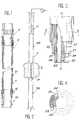
- Figures 1 and 2 show, respectively and very schematically, a expandable high pressure hose device and a example of the use of such a hose in the field the exploitation of oil wells.
- the device expandable high pressure hose or "packer”, 10 comprises an expandable tubular element or membrane 11, to base of elastomeric material, attached at both ends 12 and 13 to end caps 14 and 15, respectively, which are advantageously of the type described in EP-A1-0 516 515 in the name of the Applicant, without this indication has however some limiting character that it would be.
- two devices 10 a and 10 b with an external diameter in the unexpanded state which can be, in one embodiment of about 54 mm are mounted on a mandrel M and down through a "production tubing" diameter slightly greater to be placed on either side of a pr production zone of the well P.
- the packers 10 a and 10 b are then expanded to isolate a zone z into which is injected, by suitable devices not shown, acid sludges intended to stimulate the production zone.
- the diameter of the well or of its "casing" is, in certain cases, of the order of 162 mm, so that in order to obtain a satisfactory seal the membrane 11 must be expanded by approximately three times its initial diameter.
- the invention proposes that the membrane 11 (fixed at its ends to the end pieces 14 and 15, the first of which is, moreover, in a manner known per se mounted movable on the mandrel M) is constituted by a matrix of elastomeric material (s), advantageously a mixture of rubbers having excellent persistence under high elongation, on the one hand and, on the other hand, the required characteristics of resistance mechanical and chemical resistance.
- a matrix of elastomeric material advantageously a mixture of rubbers having excellent persistence under high elongation
- a matrix which may be, for example, of the polychloroprene type
- pressure there are at least two sets of reinforcing reinforcements, called "pressure", which, according to the invention, are in the form of woven or woven layers of wire textiles, advantageously based on aramid fibers such as Kevlar (a registered trademark of the company DUPONT DE NEMOURS).
- Kevlar a registered trademark of the company DUPONT DE NEMOURS
- At least two crossed plies 20 and 21 are arranged, the first on an internal tube 22 and the second on the first with interposition between them of a gap 23 for example, but not necessarily, in the same elastomeric material as that of the inner tube 22;
- the two plies 20, 21, -which are arranged crosswise with respect to the longitudinal axis A of the membrane-, are each made up of wires or cables, 24 for the ply 20 and 25 for the ply 21, each completely coated with elastomeric material and placed at an angle ⁇ of the order of 10 to 15 ° relative to the axis A.
- the cables 24 and 25 which are strongly adhered to the elastomeric material in which they are embedded, have a Young's modulus stronger than that of the said material and are arranged in a similar manner to the warp threads of a fabric while being maintained at a substantially constant and predetermined spacing from each other, for example using combs positioning metal during their installation. Obtained with such a structure of the pressure layers, an easy and immediate swelling of the membrane 11 even under low pressure, the diameter of the latter passing from its initial condition to the diameter d to a value of approximately 3 d for a pressure between 30 and 60 bars. It can also be seen that the cables remain perfectly in place and return to their initial position, after deflation, without distension.
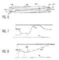
- the membrane 11 presents, in said end zones and in its swollen condition-, a shape close to that shown on Figure 8, that is to say with a part 30 whose section through a longitudinal plane is regular from end caps 14, 15 to the expanded part of the membrane, while for Art devices Prior and deprived of the means of the invention, the form after inflation of the membrane is that called “bone” long ", figure 7, where the ends are larger diameter than the central part.
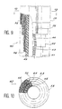
- the invention proposes, in one embodiment preferred, Figures 9 and 10, at least one holding ply screened with longitudinal wires or cabled 50 extend over substantially the entire length of the device and which are embedded in the elastomeric material constituting the membrane 40 to which they are strongly bonded, like other wires or cabled 43 and 44 of pressure screened plies 41 and 42, laid at an angle of in the range of 10 to 15 ° from the longitudinal axis of the membrane, the first on a central tube 45 in elastomeric material and the second on a gap 46, for example, but not necessarily, in the same material, the two plies being cross-arranged by relative to the longitudinal axis A.
- Longitudinal cable plies 50 can also be provided in the vicinity of the internal surface of the element, and / or between pairs of cable layers crossed, such as the pair of tablecloths 41, 42, or even between two crossed plies 41, 42.
- the invention proposes to reduce the constraints that appear the inflation of the expandable tubular element, in particular near its ends, arrange the cables reinforcements of the pressure layers as shown on the Figure 6, that is to say so that they do, -in their initial installation condition-, a variable angle with the axis A of the membrane, for example of the order of 10-12 ° in the middle zone and around 20 ° at near the ends where the end pieces 14 and 15.
- a variable angle with the axis A of the membrane, for example of the order of 10-12 ° in the middle zone and around 20 ° at near the ends where the end pieces 14 and 15.
- each layer can be further reduced by providing more than two woven tablecloths, on the one hand, and playing on the report from the density of the reinforcing cables to the quantity of elastomeric material in which they are embedded, else go.
- the invention provides for placing in each end zone of the device a winding of a fabric radially deformable.
- figure 5 the invention proposes to relate to the vicinity of membrane end fittings 11 to end caps 14 and 15, sheaths or socks 31, advantageously at reinforced edges which, after installation, are rolled up then blocked by longitudinal tie rods, 32.
- a membrane 40 of a "packer" device was made from a tube internal polychloroprene with an internal diameter of 26 mm and a thickness of 4 mm to which was reported a first screen of aramid 3300/1/3 reinforcements dtex and on said tablecloth, a 2.4 mm gap thick, which is itself covered by a second screen weave of aramid 3300/1/3 dtex reinforcements. Sure this second tablecloth is then deposited a new entreplis, itself covered with a third layer screened with 72 aramid 3300/1/3 dtex reinforcing cables themselves covered with a tubular covering, the external diameter is 53 mm.
Landscapes
- Engineering & Computer Science (AREA)
- General Engineering & Computer Science (AREA)
- Life Sciences & Earth Sciences (AREA)
- Geology (AREA)
- Mining & Mineral Resources (AREA)
- Environmental & Geological Engineering (AREA)
- Fluid Mechanics (AREA)
- General Life Sciences & Earth Sciences (AREA)
- Geochemistry & Mineralogy (AREA)
- Physics & Mathematics (AREA)
- Mechanical Engineering (AREA)
- Rigid Pipes And Flexible Pipes (AREA)
- Actuator (AREA)
- Reciprocating Pumps (AREA)
Claims (10)
- Flexible, unter hohem Druck dehnbare Einrichtung, insbesondere für das Verschließen von Schacht kanälen in Gas- oder Erdölbohrungen, die zwei Endansatzstücke (14,15) und ein rohrförmiges Element (11, 40) auf der Basis von Elastomermaterial hat, umfassend wenigstens zwei Schichten (20, 21, 41, 42) aus sehr widerstandsfähigen Textilkabeln, die schnecken- oder schraubenförmig um die Längsachse (A A) des Elements mit einem geringen Winkel von ungefähr 10 bis 15° mit Bezug auf diese Achse gewickelt sind, wobei diese Schichten in gekreuzter Anordnung zu zweien mit Bezug auf die vorgenannte Achse vorgesehen sind, dadurch gekennzeichnet, daß jede Schicht (20, 21, 41, 42) eingeschossen bzw. eingeschlagen ist und in der Kettenrichtung Textilkabel (24,25,43,44), insbesondere auf der Basis von Aramidfasern, enthält, welche voneinander durch einen vorbestimmten Zwischenraumabstand getrennt sind und welche in dem vorgenannten Elastomermaterial versenkt sind, indem sie an demselben anhaften, wobei die Vorrichtung außerdem wenigstens eine Schicht von Kabeln (50) enthält, die parallel zu der vorgenannten Längsachse (A A), über die gesamte Länge der Einrichtung sind und in dem Elastomermaterial dieses Elements (11, 14) versenkt sind, indem sie an diesem Material anhaften.
- Einrichtung gemäß Anspruch 1, dadurch gekennzeichnet, daß die Schicht von Kabeln (50), welche parallel zu der Achse (A A) sind, eingeschossen bzw. eingeschlagen ist und die Längskabel daselbst voneinander um eine vorbestimmte Entfernung beabstandet sind.
- Einrichtung gemäß Anspruch 1 oder 2, dadurch gekennzeichnet, daß der Zwischenraumabstand der benachbarten Kabel der vorgenannten Schichten während der Herstellung der Einrichtung auf einem im wesentlichen konstanten Wert gehalten ist.
- Einrichtung gemäß irgendeinem der vorhergehenden Ansprüche, dadurch gekennzeichnet, daß jede vorgenannte Schicht (20, 21, 41, 42, 50) auf der Basis von Kabeln aus Aramidfasern besteht, die vorteilhafterweise aus drei Fäden von 3.300 dtex gebildet sind, welche durch Kalandrierung oder durch einen dünnen Überzug mit einem Haft- bzw. Klebemittel behandelt sind.
- Einrichtung gemäß einem der vorhergehenden Ansprüche, dadurch gekennzeichnet, daß sich die Schicht oder Schichten aus zu der Achse (A A) parallelen Kabeln (50) in der Nähe des äußeren Umfangs (55) des rohrförmigen Elements und/oder in der Nähe seines inneren Umfangs und/oder zwischen den Paaren der Schichten von gekreuzten Kabeln und/oder zwischen zwei gekreuzten Schichten (41, 42) befindet bzw. befinden.
- Einrichtung gemäß einem der vorhergehenden Ansprüche, dadurch gekennzeichnet, daß sie thermisch isolierend ist.
- Einrichtung gemäß einem der vorhergehenden Ansprüche, dadurch gekennzeichnet, daß die eingeschossenen bzw. eingeschlagenen Schichten (20, 21, 41, 42) aus schnecken- bzw. schraubenförmig gewickelten Kabeln so gestaltet sind, daß der Winkel der Kabel in den Endzonen des rohrförmigen Elements unterschiedlich gegenüber jenem in der mittleren Zone dieses Elements ist.
- Einrichtung gemäß Anspruch 7, dadurchgekennzeichnet, daß der Winkel der anfänglichen Stellung der die Schichten (20, 21, 41, 42) bildenden Kabel in der Größenordnung von 10 bis 12° in der mittleren Zone ist, wo das Element sich bis zum dreifachen seines Anfangsdurchmessers ausdehnen muß, und 20° in den Endzonen dieses Elements ist.
- Einrichtung gemäß einem der vorhergehenden Ansprüche, dadurch gekennzeichnet, daß die Beanspruchungen, die während des Aufblähens auftreten, in der Nähe der Enden des rohrförmigen Elements (11) durch Hüllen bzw. Hülsen oder Socken (31) mit verstärkten Rändern, die über die genannten Enden aufgezogen sind, beschränkt sind, wobei diese Hüllen bzw. Hülsen oder Socken, nachdem sie an Ort und Stelle gebracht worden sind, gerafft, danach durch Verankerungen bzw. Laschen bzw. Zugglieder (32) blockiert sind.
- Einrichtung gemäß einem der vorhergenden Ansprüche , dadurch gekennzeichnet, daß die Beanspruchungen, welche während des Aufblähens auftreten, in der Nähe der Enden des rohrförmigen Elements durch Wicklungen eines radial deformierbaren Textilmaterials bzw. Tuchs begrenzt sind.
Applications Claiming Priority (3)
| Application Number | Priority Date | Filing Date | Title |
|---|---|---|---|
| FR9307317A FR2706575B1 (fr) | 1993-06-17 | 1993-06-17 | Dispositif de flexible haute pression dilatable. |
| FR9307317 | 1993-06-17 | ||
| PCT/FR1994/000732 WO1995000738A1 (fr) | 1993-06-17 | 1994-06-17 | Obturateur gonflable renforce de fond de puits |
Publications (2)
| Publication Number | Publication Date |
|---|---|
| EP0702747A1 EP0702747A1 (de) | 1996-03-27 |
| EP0702747B1 true EP0702747B1 (de) | 1998-05-20 |
Family
ID=9448239
Family Applications (1)
| Application Number | Title | Priority Date | Filing Date |
|---|---|---|---|
| EP94919728A Expired - Lifetime EP0702747B1 (de) | 1993-06-17 | 1994-06-17 | Verstärktes aufblasbares packerelement zur verwendung im bohrloch |
Country Status (7)
| Country | Link |
|---|---|
| US (1) | US5702109A (de) |
| EP (1) | EP0702747B1 (de) |
| CA (1) | CA2164336A1 (de) |
| DE (1) | DE69410461D1 (de) |
| FR (1) | FR2706575B1 (de) |
| NO (1) | NO955121L (de) |
| WO (1) | WO1995000738A1 (de) |
Cited By (1)
| Publication number | Priority date | Publication date | Assignee | Title |
|---|---|---|---|---|
| US8695717B2 (en) | 2004-11-04 | 2014-04-15 | Schlumberger Technology Corporation | Inflatable packer assembly |
Families Citing this family (32)
| Publication number | Priority date | Publication date | Assignee | Title |
|---|---|---|---|---|
| CA2300622C (en) * | 1999-03-12 | 2003-10-07 | Dale I. Kunz | Steep pitch helix packer |
| US6458233B2 (en) * | 1999-04-12 | 2002-10-01 | James V. Carisella | Method for manufacturing a wall thickness program into an elastomeric tubular component for incorporation into a packing device for use in a subterranean well |
| US6223820B1 (en) * | 1999-04-12 | 2001-05-01 | James V. Carisella | Inflatable packing device including cover means for effecting a uniform expansion profile |
| US6158506A (en) * | 1999-04-12 | 2000-12-12 | Carisella; James V. | Inflatable packing device including components for effecting a uniform expansion profile |
| US6431275B1 (en) | 1999-07-19 | 2002-08-13 | Baker Hughes Incorporated | Inflation control device |
| FR2856456B1 (fr) * | 2003-06-20 | 2005-09-09 | Schlumberger Services Petrol | Dispositif d'etancheite pour l'obturation temporaire d'un puits ou d'une canalisation. |
| US7380595B2 (en) * | 2004-01-21 | 2008-06-03 | Schlumberger Technology Corporation | System and method to deploy and expand tubular components deployed through tubing |
| US7828054B2 (en) * | 2004-06-08 | 2010-11-09 | Schlumberger Technology Corporation | Packer cable sealing system |
| FR2873057B1 (fr) * | 2004-07-15 | 2007-11-09 | Epsilon Composite Sarl Sarl | Procede de fabrication de tubes composites par pultrusion et tubes obtenus |
| FR2875286B1 (fr) * | 2004-09-13 | 2008-04-25 | Saltel Ind Soc Par Actions Sim | Dispositif d'etancheite servant a obturer un puits ou une canalisation |
| US7392851B2 (en) | 2004-11-04 | 2008-07-01 | Schlumberger Technology Corporation | Inflatable packer assembly |
| US8894069B2 (en) * | 2005-03-30 | 2014-11-25 | Schlumberger Technology Corporation | Inflatable packers |
| US7363970B2 (en) * | 2005-10-25 | 2008-04-29 | Schlumberger Technology Corporation | Expandable packer |
| US7510015B2 (en) | 2006-02-23 | 2009-03-31 | Schlumberger Technology Corporation | Packers and methods of use |
| NO329296B1 (no) * | 2006-06-16 | 2010-09-27 | Nils Petter Vedvik | En forbindelse mellom et stivt stykke og et komposittmateriale |
| US9322240B2 (en) * | 2006-06-16 | 2016-04-26 | Schlumberger Technology Corporation | Inflatable packer with a reinforced sealing cover |
| US7647980B2 (en) * | 2006-08-29 | 2010-01-19 | Schlumberger Technology Corporation | Drillstring packer assembly |
| FR2910047B1 (fr) * | 2006-12-18 | 2015-02-20 | Francis Cour | Manchon gonflable a deformation controlee, procede de fabrication, et application a la pressiometrie |
| WO2009090393A2 (en) | 2008-01-16 | 2009-07-23 | Ready Set Goal Ltd. | Temporary support |
| GB2464757B (en) * | 2008-10-28 | 2013-04-10 | Bdz Holdings Ltd | Tubular member |
| US7699124B2 (en) | 2008-06-06 | 2010-04-20 | Schlumberger Technology Corporation | Single packer system for use in a wellbore |
| US8028756B2 (en) | 2008-06-06 | 2011-10-04 | Schlumberger Technology Corporation | Method for curing an inflatable packer |
| US7874356B2 (en) | 2008-06-13 | 2011-01-25 | Schlumberger Technology Corporation | Single packer system for collecting fluid in a wellbore |
| US8091634B2 (en) | 2008-11-20 | 2012-01-10 | Schlumberger Technology Corporation | Single packer structure with sensors |
| US8573314B2 (en) * | 2008-11-20 | 2013-11-05 | Schlumberger Technology Corporation | Packer system with reduced friction during actuation |
| US8113293B2 (en) | 2008-11-20 | 2012-02-14 | Schlumberger Technology Corporation | Single packer structure for use in a wellbore |
| US8474524B2 (en) * | 2009-05-21 | 2013-07-02 | Schlumberger Technology Corporation | Anti-extrusion packer system |
| US8336181B2 (en) | 2009-08-11 | 2012-12-25 | Schlumberger Technology Corporation | Fiber reinforced packer |
| FR3009841B1 (fr) * | 2013-08-20 | 2015-09-18 | Calyf | Manchon gonflable, a expansion controlee |
| FR3022577B1 (fr) * | 2014-06-18 | 2016-07-29 | Saltel Ind | Dispositif de chemisage ou d'obturation d'un puits ou d'une canalisation |
| FR3042573B1 (fr) * | 2015-10-19 | 2018-03-30 | Sotra Seperef | Dispositif d’obturation pour regler la pression ou le debit d’ecoulement dans un tube, et procede de fabrication d’un tube |
| US10174581B2 (en) * | 2015-10-23 | 2019-01-08 | Baker Hughes, A Ge Company, Llc | Method and apparatus to utilize a deformable filler ring |
Family Cites Families (12)
| Publication number | Priority date | Publication date | Assignee | Title |
|---|---|---|---|---|
| US2643722A (en) * | 1948-02-26 | 1953-06-30 | Lynes Inc | Hydraulically inflatable packer |
| US3442123A (en) * | 1967-05-01 | 1969-05-06 | Yvon Marie Xavier Broise | Testing probe for soils |
| US3542127A (en) * | 1968-05-13 | 1970-11-24 | Lynes Inc | Reinforced inflatable packer with expansible back-up skirts for end portions |
| US4191383A (en) * | 1979-02-02 | 1980-03-04 | Halliburton Company | Inflatable packer and method of constructing same |
| US4311314A (en) * | 1980-11-20 | 1982-01-19 | Suman George O | Well packer |
| FR2506893B1 (fr) * | 1981-05-27 | 1986-01-03 | Caoutchouc Manuf Plastique | Dispositif d'obturation temporaire des canalisations ou trous de forage |
| US4614346A (en) * | 1982-03-12 | 1986-09-30 | The Gates Rubber Company | Inflatable unitary packer element having elastic recovery |
| US4514447A (en) * | 1984-03-23 | 1985-04-30 | Boxmeyer James G | Inflatable structural column |
| US5183108A (en) * | 1991-08-19 | 1993-02-02 | The Gates Rubber Company | Inflatable packer |
| US5236201A (en) * | 1991-10-29 | 1993-08-17 | Vance Sr James C | Reinforcement structure for inflatable downhole packers |
| AU656235B2 (en) * | 1991-10-29 | 1995-01-27 | Gates Rubber Company, The | Improved reinforcement structure for inflatable downhole packers |
| US5205567A (en) * | 1991-10-30 | 1993-04-27 | The Gates Rubber Company | Reinforced inflatable packer |
-
1993
- 1993-06-17 FR FR9307317A patent/FR2706575B1/fr not_active Expired - Fee Related
-
1994
- 1994-06-17 DE DE69410461T patent/DE69410461D1/de not_active Expired - Lifetime
- 1994-06-17 US US08/571,902 patent/US5702109A/en not_active Expired - Fee Related
- 1994-06-17 EP EP94919728A patent/EP0702747B1/de not_active Expired - Lifetime
- 1994-06-17 CA CA002164336A patent/CA2164336A1/fr not_active Abandoned
- 1994-06-17 WO PCT/FR1994/000732 patent/WO1995000738A1/fr not_active Ceased
-
1995
- 1995-12-15 NO NO955121A patent/NO955121L/no unknown
Cited By (1)
| Publication number | Priority date | Publication date | Assignee | Title |
|---|---|---|---|---|
| US8695717B2 (en) | 2004-11-04 | 2014-04-15 | Schlumberger Technology Corporation | Inflatable packer assembly |
Also Published As
| Publication number | Publication date |
|---|---|
| NO955121D0 (no) | 1995-12-15 |
| FR2706575B1 (fr) | 1995-09-01 |
| EP0702747A1 (de) | 1996-03-27 |
| DE69410461D1 (de) | 1998-06-25 |
| FR2706575A1 (fr) | 1994-12-23 |
| NO955121L (no) | 1996-02-15 |
| CA2164336A1 (fr) | 1995-01-05 |
| US5702109A (en) | 1997-12-30 |
| WO1995000738A1 (fr) | 1995-01-05 |
Similar Documents
| Publication | Publication Date | Title |
|---|---|---|
| EP0702747A1 (de) | Verstärktes aufblasbares packerelement zur verwendung im bohrloch | |
| FR2875286A1 (fr) | Dispositif d'etancheite servant a obturer un puits ou une canalisation | |
| EP1104527B1 (de) | Biegsame rohrleitung mit kriechbegrenzter dichtschicht | |
| EP0527932B1 (de) | Vorformmittel und verfahren zum verrohren und/oder auskleiden eines zylindrischen volumens | |
| US6561278B2 (en) | Methods and apparatus for interconnecting well tool assemblies in continuous tubing strings | |
| EP0080918B1 (de) | Absperrorgan für Leitungen | |
| EP0296056B1 (de) | Element mit veränderlicher Steifheit für die Verwendung am Fuss einer Übergabeleitung | |
| WO2008145861A2 (fr) | Conduite tubulaire flexible pour le transport d'hydrocarbures gazeux | |
| WO1999025951A1 (fr) | Dispositif de mise en place d'une enveloppe filtrante a l'interieur d'un puits | |
| FR2897664A1 (fr) | Garnitures d'etancheite et procede d'utilisation. | |
| FR2712024A1 (fr) | Système de complétion à tube de production, flexible enroulable. | |
| FR2850128A1 (fr) | Structure composite deformable multicouche, destinee a etre utilisee dans un puits souterrain. | |
| FR2808557A1 (fr) | Procede et dispositif pour la regulation du debit des fluides de formation produits par un puits petrolier ou analogue | |
| FR2851635A1 (fr) | Manchon a insert pour la reparation d'une canalisation de transport de fluide a haute pression | |
| FR3028913A1 (fr) | Couche d'isolation thermique pour conduite tubulaire flexible sous-marine | |
| EP1364147A1 (de) | Biegsame leitung mit einer das " sich-senken" der dichtungsschicht verhinderden zwischenschicht | |
| FR2716925A1 (fr) | Raccord à portée interne, destiné à être positionné dans un tube de production flexible. | |
| WO2009147064A1 (fr) | Conduite flexible à embouts d'extrémité intégrés | |
| FR2700826A1 (fr) | Tuyau flexible flottant. | |
| WO2007063016A1 (fr) | Procédé et dispositif de cimentation d'un puits ou d'une canalisation | |
| WO2003083343A1 (fr) | Dispositif pour limiter le flambage lateral des nappes d'armures d'une conduite flexible | |
| FR2706525A1 (fr) | Procédé et dispositif pour raccorder intérieurement un tube de production bobiné. | |
| US8336181B2 (en) | Fiber reinforced packer | |
| WO2015193404A1 (fr) | Dispositif de chemisage ou d'obturation d'un puits ou d'une canalisation | |
| FR2523206A1 (fr) | Packer gonflable pour sondages |
Legal Events
| Date | Code | Title | Description |
|---|---|---|---|
| PUAI | Public reference made under article 153(3) epc to a published international application that has entered the european phase |
Free format text: ORIGINAL CODE: 0009012 |
|
| 17P | Request for examination filed |
Effective date: 19951213 |
|
| AK | Designated contracting states |
Kind code of ref document: A1 Designated state(s): BE CH DE DK ES GB IE IT LI LU NL SE |
|
| 17Q | First examination report despatched |
Effective date: 19960521 |
|
| GRAG | Despatch of communication of intention to grant |
Free format text: ORIGINAL CODE: EPIDOS AGRA |
|
| GRAG | Despatch of communication of intention to grant |
Free format text: ORIGINAL CODE: EPIDOS AGRA |
|
| GRAH | Despatch of communication of intention to grant a patent |
Free format text: ORIGINAL CODE: EPIDOS IGRA |
|
| GRAH | Despatch of communication of intention to grant a patent |
Free format text: ORIGINAL CODE: EPIDOS IGRA |
|
| GRAA | (expected) grant |
Free format text: ORIGINAL CODE: 0009210 |
|
| AK | Designated contracting states |
Kind code of ref document: B1 Designated state(s): BE CH DE DK ES GB IE IT LI LU NL SE |
|
| PG25 | Lapsed in a contracting state [announced via postgrant information from national office to epo] |
Ref country code: NL Free format text: LAPSE BECAUSE OF FAILURE TO SUBMIT A TRANSLATION OF THE DESCRIPTION OR TO PAY THE FEE WITHIN THE PRESCRIBED TIME-LIMIT Effective date: 19980520 Ref country code: IT Free format text: LAPSE BECAUSE OF FAILURE TO SUBMIT A TRANSLATION OF THE DESCRIPTION OR TO PAY THE FEE WITHIN THE PRESCRIBED TIME-LIMIT;WARNING: LAPSES OF ITALIAN PATENTS WITH EFFECTIVE DATE BEFORE 2007 MAY HAVE OCCURRED AT ANY TIME BEFORE 2007. THE CORRECT EFFECTIVE DATE MAY BE DIFFERENT FROM THE ONE RECORDED. Effective date: 19980520 Ref country code: ES Free format text: THE PATENT HAS BEEN ANNULLED BY A DECISION OF A NATIONAL AUTHORITY Effective date: 19980520 |
|
| REG | Reference to a national code |
Ref country code: CH Ref legal event code: EP |
|
| PG25 | Lapsed in a contracting state [announced via postgrant information from national office to epo] |
Ref country code: LU Free format text: LAPSE BECAUSE OF NON-PAYMENT OF DUE FEES Effective date: 19980617 |
|
| REF | Corresponds to: |
Ref document number: 69410461 Country of ref document: DE Date of ref document: 19980625 |
|
| PG25 | Lapsed in a contracting state [announced via postgrant information from national office to epo] |
Ref country code: LI Free format text: LAPSE BECAUSE OF NON-PAYMENT OF DUE FEES Effective date: 19980630 Ref country code: CH Free format text: LAPSE BECAUSE OF NON-PAYMENT OF DUE FEES Effective date: 19980630 Ref country code: BE Free format text: LAPSE BECAUSE OF NON-PAYMENT OF DUE FEES Effective date: 19980630 |
|
| GBT | Gb: translation of ep patent filed (gb section 77(6)(a)/1977) |
Effective date: 19980612 |
|
| PG25 | Lapsed in a contracting state [announced via postgrant information from national office to epo] |
Ref country code: SE Free format text: LAPSE BECAUSE OF FAILURE TO SUBMIT A TRANSLATION OF THE DESCRIPTION OR TO PAY THE FEE WITHIN THE PRESCRIBED TIME-LIMIT Effective date: 19980820 Ref country code: DK Free format text: LAPSE BECAUSE OF FAILURE TO SUBMIT A TRANSLATION OF THE DESCRIPTION OR TO PAY THE FEE WITHIN THE PRESCRIBED TIME-LIMIT Effective date: 19980820 |
|
| PG25 | Lapsed in a contracting state [announced via postgrant information from national office to epo] |
Ref country code: DE Free format text: LAPSE BECAUSE OF FAILURE TO SUBMIT A TRANSLATION OF THE DESCRIPTION OR TO PAY THE FEE WITHIN THE PRESCRIBED TIME-LIMIT Effective date: 19980821 |
|
| REG | Reference to a national code |
Ref country code: IE Ref legal event code: FG4D Free format text: FRENCH |
|
| NLV1 | Nl: lapsed or annulled due to failure to fulfill the requirements of art. 29p and 29m of the patents act | ||
| PG25 | Lapsed in a contracting state [announced via postgrant information from national office to epo] |
Ref country code: IE Free format text: LAPSE BECAUSE OF NON-PAYMENT OF DUE FEES Effective date: 19981211 |
|
| REG | Reference to a national code |
Ref country code: IE Ref legal event code: FD4D |
|
| BERE | Be: lapsed |
Owner name: HUTCHINSON Effective date: 19980630 |
|
| REG | Reference to a national code |
Ref country code: CH Ref legal event code: PL |
|
| PLBE | No opposition filed within time limit |
Free format text: ORIGINAL CODE: 0009261 |
|
| STAA | Information on the status of an ep patent application or granted ep patent |
Free format text: STATUS: NO OPPOSITION FILED WITHIN TIME LIMIT |
|
| 26N | No opposition filed | ||
| PGFP | Annual fee paid to national office [announced via postgrant information from national office to epo] |
Ref country code: GB Payment date: 19990601 Year of fee payment: 6 |
|
| PG25 | Lapsed in a contracting state [announced via postgrant information from national office to epo] |
Ref country code: GB Free format text: LAPSE BECAUSE OF NON-PAYMENT OF DUE FEES Effective date: 20000617 |
|
| GBPC | Gb: european patent ceased through non-payment of renewal fee |
Effective date: 20000617 |