EP0702765B1 - Rohrverbindung - Google Patents
Rohrverbindung Download PDFInfo
- Publication number
- EP0702765B1 EP0702765B1 EP93916336A EP93916336A EP0702765B1 EP 0702765 B1 EP0702765 B1 EP 0702765B1 EP 93916336 A EP93916336 A EP 93916336A EP 93916336 A EP93916336 A EP 93916336A EP 0702765 B1 EP0702765 B1 EP 0702765B1
- Authority
- EP
- European Patent Office
- Prior art keywords
- intermediate member
- coupling joint
- joint according
- diameter
- longitudinal direction
- Prior art date
- Legal status (The legal status is an assumption and is not a legal conclusion. Google has not performed a legal analysis and makes no representation as to the accuracy of the status listed.)
- Expired - Lifetime
Links
- 230000008878 coupling Effects 0.000 title claims abstract description 23
- 238000010168 coupling process Methods 0.000 title claims abstract description 23
- 238000005859 coupling reaction Methods 0.000 title claims abstract description 23
- 238000004804 winding Methods 0.000 claims abstract description 3
- 238000007789 sealing Methods 0.000 claims description 11
- 150000001875 compounds Chemical class 0.000 claims description 6
- 239000000463 material Substances 0.000 claims description 6
- 238000005520 cutting process Methods 0.000 claims description 2
- 239000003566 sealing material Substances 0.000 claims 2
- 239000007787 solid Substances 0.000 description 4
- 238000005452 bending Methods 0.000 description 3
- 239000002184 metal Substances 0.000 description 3
- 238000012986 modification Methods 0.000 description 2
- 230000004048 modification Effects 0.000 description 2
- 239000004033 plastic Substances 0.000 description 2
- 229920003023 plastic Polymers 0.000 description 2
- 230000006978 adaptation Effects 0.000 description 1
- 238000002485 combustion reaction Methods 0.000 description 1
- 230000006835 compression Effects 0.000 description 1
- 238000007906 compression Methods 0.000 description 1
- 230000008602 contraction Effects 0.000 description 1
- 229920001971 elastomer Polymers 0.000 description 1
- 230000002349 favourable effect Effects 0.000 description 1
- 238000003780 insertion Methods 0.000 description 1
- 230000037431 insertion Effects 0.000 description 1
- 238000009434 installation Methods 0.000 description 1
- 229920003051 synthetic elastomer Polymers 0.000 description 1
- 238000009423 ventilation Methods 0.000 description 1
Images
Classifications
-
- F—MECHANICAL ENGINEERING; LIGHTING; HEATING; WEAPONS; BLASTING
- F16—ENGINEERING ELEMENTS AND UNITS; GENERAL MEASURES FOR PRODUCING AND MAINTAINING EFFECTIVE FUNCTIONING OF MACHINES OR INSTALLATIONS; THERMAL INSULATION IN GENERAL
- F16L—PIPES; JOINTS OR FITTINGS FOR PIPES; SUPPORTS FOR PIPES, CABLES OR PROTECTIVE TUBING; MEANS FOR THERMAL INSULATION IN GENERAL
- F16L25/00—Construction or details of pipe joints not provided for in, or of interest apart from, groups F16L13/00 - F16L23/00
- F16L25/10—Sleeveless joints between two pipes, one being introduced into the other
-
- F—MECHANICAL ENGINEERING; LIGHTING; HEATING; WEAPONS; BLASTING
- F16—ENGINEERING ELEMENTS AND UNITS; GENERAL MEASURES FOR PRODUCING AND MAINTAINING EFFECTIVE FUNCTIONING OF MACHINES OR INSTALLATIONS; THERMAL INSULATION IN GENERAL
- F16L—PIPES; JOINTS OR FITTINGS FOR PIPES; SUPPORTS FOR PIPES, CABLES OR PROTECTIVE TUBING; MEANS FOR THERMAL INSULATION IN GENERAL
- F16L37/00—Couplings of the quick-acting type
- F16L37/02—Couplings of the quick-acting type in which the connection is maintained only by friction of the parts being joined
- F16L37/04—Couplings of the quick-acting type in which the connection is maintained only by friction of the parts being joined with an elastic outer part pressing against an inner part by reason of its elasticity
-
- Y—GENERAL TAGGING OF NEW TECHNOLOGICAL DEVELOPMENTS; GENERAL TAGGING OF CROSS-SECTIONAL TECHNOLOGIES SPANNING OVER SEVERAL SECTIONS OF THE IPC; TECHNICAL SUBJECTS COVERED BY FORMER USPC CROSS-REFERENCE ART COLLECTIONS [XRACs] AND DIGESTS
- Y10—TECHNICAL SUBJECTS COVERED BY FORMER USPC
- Y10S—TECHNICAL SUBJECTS COVERED BY FORMER USPC CROSS-REFERENCE ART COLLECTIONS [XRACs] AND DIGESTS
- Y10S285/00—Pipe joints or couplings
- Y10S285/91—Gaskets
Definitions
- the present invention relates to a coupling joint, arranged to join a first element having a substantially circular internal envelope surface to a second element, inserted into the first element, having a substantially circular envelope surface with a smaller diameter than the internal diameter of the first element.
- US-A-2085907 discloses such a joint comprising a stripshaped intermediate member consisting of one or more bushings comprising a length of flexible tubular metal split longitudinally to permit circumferential contraction, and the first element being pressed against the intermediate member by clamping means causing the intermediate member to be compressed and pressed against adjacent envelope sufaces of the elements.
- the object of the present invention is to disclose a coupling joint, which easily can be adjusted to actual diameter difference within a certain predetermined range, and which facilitates accomplishing of a joint which is resistant against vibrational and bending forces, and which also can be arranged having very good sealing properties.
- the joint is in particular suitable as a coupling joint between two tubular elements or hoses, but can also be used for applications when one of the elements have a substantially solid cross-section.
- the joint can be mounted quickly and simple, without use of special purpose tools.
- the coupling joint according to the present invention is arranged to join a first element having a substantially circular internal envelope surface with a second element, inserted in a longitudinal direction into the first element and having a smaller external diameter than the internal diameter of the first element wherein a helically wound and in longitudinal direction corrugated or creased stripshaped intermediate member is arranged in an intermediate position between the first and the second element, and wherein at least one of the elements is pressed against the intermediate member by expanding or clamping means causing the intermediate member to be compressed and pressed against adjacent envelope surfaces of the elements.
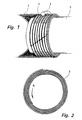
- Fig. 1 shows an example of an embodiment of a coupling joint according to the invention, arranged to join a first and external tubular element 1 with a second tubular element 2, inserted into the first element 1.
- the second element 2 has an external diameter which is considerably smaller than the internal diameter of the first element 1, said difference in diameter preventing establishment of a joint by use of a clamping joint, e.g. established by means of a conventional tube clamp.
- an intermediate member as a complete unit denominated 3, comprising a corrugated or creased stripshaped member having a number onto each other wound layers, almost comparable with a helically wound blade spring, which is also shown in Fig. 2.
- the intermediate member 3 is applied against the second element 2, and by applying a turning force against the outer portion of the intermediate member 3, directed against the winding direction, the adjacent turns are separated from each other, whereby application of same can be easily accomplished.
- Adjustment of the number of wound turns can alternatively be carried out either before or after mounting against said second element 2, in order to adjust the external diameter of the intermediate member 3 when mounted to the internal diameter of the first element 1.
- the second element 2 When inserting the second element 2 and onto same applied intermediate member 3 into the first element 1, the second element 2 is preferably rotated in the direction indicated by the arrow A in Fig. 1, whereby onto each other located wound turns of the intermediate member 3 take up a more adjacent position to each other facilitating insertion into the first element 1.
- the outer turn of the intermediate member 3 When such a rotary influence is terminated, the outer turn of the intermediate member 3 will be pressed against the internal envelope surface of the first element 1.
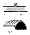
- a conventional tube clamp 4, as indicated in Figs. 1 and 3 is used to additionally press the first element 1 against the intermediate member 3. As shown in Fig. 3, such a compression will cause the wall of the first external element 1 to be plastically deformed into engagement with the outer wound turn.
- the intermediate member 3 Simultaneously can also the intermediate member 3 obviously be compressed, and thus expand to an increased width.
- This will result in that the outer free edge portions of the innermost wound turn somewhat engage with the external wall of the second element 2, and that said engagement results in a pile-up of material in front of said edge portions, as illustrated in Fig. 3.
- the intermediate member 3 is thus locked in an extremely good fashion against the embraced second element 2, and the aforementioned plastical deformation of the first element 1 also results in that said element 1 is locked in an efficient fashion in relation to the intermediate member 3.
- the corrugated shape of the intermediate member 3 results in that both vibrational influence as well as bending influence will be taken up by the joint in an extremely good fashion.
- the joint according to the present invention can be further modified.
- a layer of a sealing compound can be applied against the internal and external surfaces of the intermediate member 3, and for further improved sealing, such a compound may also be applied between adjacently located wound turns.
- the expression sealing compound also includes materials having sealing properties in another form than a compound, e.g. in the form of a tape.
- the terminating part of the strip forming the intermediate member 3 can also be arranged as a part cut in inclined direction to the centre axis, and in a similar fashion the first part of said strip can obviously be arranged with an edge portion cut in an inclined direction.
- the intermediate member 3 is as shown formed from a strip with substantially V-shaped and in relation to each other parallel corrugations or creases.
- Said corrugations can obviously be arranged having other cross-sectional configuration, e.g. U-shaped, and may also for certain applications include corrugations or creases extending substantially parallel but inclined in relation to the longitudinal direction of the strip, particularly for those cases when sealing properties are of minor interest.
- the second and inside element 2 may also comprise of a solid element.
- the first and external element 1 may also comprise of a non-deformable element, provided that one or a number of diametrically expandable means can be arranged inside the second element 2, and press the second element 2 against the intermediate member 3.
- the external edge portions of the intermediate member 3 are preferably arranged directed towards the first element 1, i.e. in an opposed directed relationship in relation to what is shown in Fig. 3.
- markings which indicate suitable points to make a cut in order to accomplish diameter changes of for example 0,5 or 1 mm.
- markings can also be arranged as fractural impressions, i.e. embossments or similar that reduce the thickness of the strip, in order to facilitate a further simplified adjustment to desired diameter.
- the described design facilitates that the established joint in an extremely good fashion can take up existing vibrations, breaking forces and similar, since the intermediate member 3 almost can be regarded as a longitudinally extending spring unit, well adapted to take up various forces, which is clearly shown in Fig. 3.
- the intermediate member is also preferably manufactured from metal, even though plastics and similar materials also can be used for certain applications.
- the coupling joint according to the present invention can further obviously be used to join elements of plastics, rubber, artificial rubber and other materials, in which cases the intermediate member 3 is manufactured from a material suitable for such fields of application.
- the intermediate member 3 is preferably arranged adapted to facilitate attachment to an embraced second element 2 having a diameter within a predetermined range, e.g. 25 - 28 mm, and with possibility for adjustment within a larger diameter range with regard to the external first element 1, e.g. 40 - 80 mm.
- a predetermined range e.g. 25 - 28 mm
- the external first element 1 e.g. 40 - 80 mm.
- fractural impressions or markings facilitate simple adjustment of the internal diameter
- same can also be adjusted in a simple fashion within a larger diameter range. Adjustment of the internal diameter is facilitated by "pulling" the internal part of the strip in a sidedirected relationship, and by cutting. Said part returns thereafter to its original position due to the resilient or elastic properties of the strip.
Landscapes
- Engineering & Computer Science (AREA)
- General Engineering & Computer Science (AREA)
- Mechanical Engineering (AREA)
- Orthopedics, Nursing, And Contraception (AREA)
- Materials For Photolithography (AREA)
- Exhaust Silencers (AREA)
- Non-Disconnectible Joints And Screw-Threaded Joints (AREA)
- Mechanical Coupling Of Light Guides (AREA)
- Mutual Connection Of Rods And Tubes (AREA)
- Joints Allowing Movement (AREA)
- Rigid Pipes And Flexible Pipes (AREA)
Claims (10)
- Kupplungsverbindung, die angeordnet ist, um ein erstes Element (1) mit einer im wesentlichen kreisförmigen inneren Hülloberfläche mit einem zweiten Element (2) zu verbinden, das in longitudinaler Richtung in das erste Element (1) eingeführt ist, und das einen kleineren Außendurchmesser als der Innendurchmesser des ersten Elements (1) aufweist, wobei ein spiralförmig gewickeltes und in der longitudinalen Richtung gewelltes oder gefaltetes streifenförmiges Zwischenbauglied (3) an einer Zwischenposition zwischen dem ersten und dem zweiten Element (1 bzw. 2) angeordnet ist, und wobei zumindest eines der Elemente (1; 2) durch eine Ausweitungs- oder Klemmeinrichtung (4) gegen das Zwischenbauglied (3) gedrückt wird, wodurch bewirkt wird, daß das Zwischenbauglied (3) zusammengedrückt und gegen benachbarte Hülloberflächen der Elemente (1; 2) gedrückt wird.
- Kupplungsverbindung gemäß Anspruch 1, dadurch gekennzeichnet, daß die Seitenkantenabschnitte des Zwischenbauglieds (3) derart angeordnet sind, daß sie sich zu ein und demselben Element (1; 2) erstrecken.
- Kupplungsverbindung gemäß einem der Ansprüche 1 und 2, dadurch gekennzeichnet, daß zumindest ein Endabschnitt des streifenförmigen Zwischenbauglieds (3) angeordnet ist, daß er eine Erstreckung hat, die nicht zu einer Linie ähnlich ist, die mit der Windungsmitte für das Zwischenbauglied (3) zusammenfällt.
- Kupplungsverbindung gemäß einem der Ansprüche 1 bis 3, dadurch gekennzeichnet, daß die Wellungen oder Falze des Zwischenbauglieds (3) als eine Anzahl von zueinander parallelen Wellen oder Falzen angeordnet sind, die sich in der longitudinalen Richtung des streifenförmigen Bauglieds erstrecken.
- Kupplungsverbindung gemäß einem der Ansprüche 1 bis 3, dadurch gekennzeichnet, daß die Wellungen oder Falze des Zwischenbauglieds (3) als Anzahl von zueinander parallelen Wellen oder Falzen angeordnet sind, die sich in einer geneigten Beziehung bezüglich der longitudinalen Richtung des streifenförmigen Bauglieds erstrecken.
- Kupplungsverbindung gemäß einem der Ansprüche 1 bis 5, dadurch gekennzeichnet, daß ein Abdichtungsmaterial oder eine Verbindung zwischen jeweils benachbart zueinander positionierten Wicklungswindungen des Zwischenbauglieds positioniert ist.
- Kupplungsverbindung gemäß einem der Ansprüche 1 bis 6, dadurch gekennzeichnet, daß ein Abdichtungsmaterial oder eine Verbindung angeordnet ist, um eine umgebende Abdichtungsschicht durch die externen und/oder internen Wicklungswindungen des Zwischenbauglieds (3) zu bilden.
- Kupplungsverbindung gemäß einem der Ansprüche 1 bis 7, dadurch gekennzeichnet, daß das Zwischenbauglied (3) angeordnet ist, um eine oder eine Anzahl von Markierungen zu haben, die vorbestimmte Positionen offenbaren, an denen eine Schneideoperation eine vorbestimmte Durchmesseränderung bezüglich des äußeren und/oder inneren Durchmessers des Zwischenbauglieds (3) zur Folge hat.
- Kupplungsverbindung gemäß Anspruch 8, dadurch gekennzeichnet, daß solche Markierungen als Teilvertiefungen gebildet sind, welche die Warendicke des Zwischenbauglieds (3) reduzieren.
- Kupplungsverbindung gemäß einem der Ansprüche 1 bis 9, dadurch gekennzeichnet, daß das Zwischenbauglied (3) aus einem Material mit nachgiebigen oder elastischen Eigenschaften hergestellt ist.
Applications Claiming Priority (2)
| Application Number | Priority Date | Filing Date | Title |
|---|---|---|---|
| SE9103638A SE469532B (sv) | 1991-12-06 | 1991-12-06 | Skarvfoerband |
| PCT/SE1993/000484 WO1994029628A1 (en) | 1991-12-06 | 1993-06-04 | Coupling joint |
Publications (2)
| Publication Number | Publication Date |
|---|---|
| EP0702765A1 EP0702765A1 (de) | 1996-03-27 |
| EP0702765B1 true EP0702765B1 (de) | 1998-10-07 |
Family
ID=20384554
Family Applications (1)
| Application Number | Title | Priority Date | Filing Date |
|---|---|---|---|
| EP93916336A Expired - Lifetime EP0702765B1 (de) | 1991-12-06 | 1993-06-04 | Rohrverbindung |
Country Status (6)
| Country | Link |
|---|---|
| US (1) | US5732982A (de) |
| EP (1) | EP0702765B1 (de) |
| AT (1) | ATE172012T1 (de) |
| DE (1) | DE69321487T2 (de) |
| SE (1) | SE469532B (de) |
| WO (1) | WO1994029628A1 (de) |
Families Citing this family (2)
| Publication number | Priority date | Publication date | Assignee | Title |
|---|---|---|---|---|
| US8444185B2 (en) * | 2009-06-24 | 2013-05-21 | Parker-Hanninfin Corporation | Flexible extrusion resistant ring seal assembly |
| US10514119B2 (en) * | 2016-11-22 | 2019-12-24 | Schauenburg Flexadux Corporation | Duct coupling system |
Family Cites Families (11)
| Publication number | Priority date | Publication date | Assignee | Title |
|---|---|---|---|---|
| US58469A (en) * | 1866-10-02 | Improvement in well-packings | ||
| US180911A (en) * | 1876-08-08 | Improvement in pipe-connections | ||
| FR738480A (fr) * | 1932-06-10 | 1932-12-26 | Procédé et dispositif de raccordement pour tuyaux | |
| US2052603A (en) * | 1932-09-09 | 1936-09-01 | Johns Manville | Article of manufacture |
| US2085907A (en) * | 1936-07-20 | 1937-07-06 | Basca Mfg Company Inc | Multiple bushing |
| US2259609A (en) * | 1940-04-12 | 1941-10-21 | Flexitallic Gasket Co Inc | Gasket |
| US3038553A (en) * | 1960-08-26 | 1962-06-12 | Melville F Peters | Flexible fluid coupling and sound attenuating assemblies |
| US3376060A (en) * | 1964-12-14 | 1968-04-02 | Shinko Wire Co Ltd | Metallic member and joint assembly |
| US3926445A (en) * | 1972-05-04 | 1975-12-16 | Farnam Co F D | Convolutely wound gasket |
| US4516782A (en) * | 1977-11-30 | 1985-05-14 | Metex Corporation | Method of producing high temperature composite seal |
| US4773680A (en) * | 1984-09-04 | 1988-09-27 | Beta Phase, Inc. | Pipe couplers |
-
1991
- 1991-12-06 SE SE9103638A patent/SE469532B/sv not_active IP Right Cessation
-
1993
- 1993-06-04 US US08/553,500 patent/US5732982A/en not_active Expired - Fee Related
- 1993-06-04 WO PCT/SE1993/000484 patent/WO1994029628A1/en not_active Ceased
- 1993-06-04 EP EP93916336A patent/EP0702765B1/de not_active Expired - Lifetime
- 1993-06-04 DE DE69321487T patent/DE69321487T2/de not_active Expired - Fee Related
- 1993-06-04 AT AT93916336T patent/ATE172012T1/de not_active IP Right Cessation
Also Published As
| Publication number | Publication date |
|---|---|
| US5732982A (en) | 1998-03-31 |
| WO1994029628A1 (en) | 1994-12-22 |
| DE69321487T2 (de) | 1999-04-22 |
| EP0702765A1 (de) | 1996-03-27 |
| SE469532B (sv) | 1993-07-19 |
| SE9103638D0 (sv) | 1991-12-06 |
| SE9103638L (sv) | 1993-06-07 |
| ATE172012T1 (de) | 1998-10-15 |
| DE69321487D1 (de) | 1998-11-12 |
Similar Documents
| Publication | Publication Date | Title |
|---|---|---|
| KR940011855B1 (ko) | 파이프 커플링 | |
| FI106403B (fi) | Putkisinkiläliitin | |
| US4919682A (en) | Metal clamp for joining pipes | |
| CA2010202A1 (en) | Internal expansion coupling device | |
| KR19980081171A (ko) | 도관부품 사이의 차단접합부와 이러한 접합부 내에 사용가능한금속제의 긴 틈새가 있는 밴드 | |
| BR9907758A (pt) | Conexão de tubulação e colar rosqueado para a mesma | |
| CN1004167B (zh) | 管接头 | |
| JPH0617985A (ja) | ホースクランプ装置に使用されるインサート部材 | |
| CN1034610A (zh) | 用于联接金属管的夹紧环管接头 | |
| KR20000016764A (ko) | 홈관용 회전방지 신속 연결 커넥터 | |
| EP0530179A1 (de) | Vorrichtung zur verbindung eines schlauches mit einem fitting | |
| EP0610011B1 (de) | Rohrförmige Kupplung | |
| US4191384A (en) | Method and device for sealing a pipe joint | |
| US20050109415A1 (en) | Two piece air duct section | |
| GB2127922A (en) | Pipe seal | |
| EP0702765B1 (de) | Rohrverbindung | |
| EP0002959B1 (de) | Rohrverbindungen | |
| JPH0131074B2 (de) | ||
| WO2011037267A1 (ja) | ホース継手 | |
| JP3422836B2 (ja) | クランプ用スプリングカラー | |
| GB1594557A (en) | Sealing a pipe joint | |
| JPH05272673A (ja) | スイベル型端部継手及びこれをホースの端部に固定するための固定方法 | |
| EP3583342B1 (de) | Schraubverbindung für ein gasrohr aus metall | |
| JPS6028862Y2 (ja) | ホ−ス等の接続具 | |
| JP2010019311A (ja) | 配管と継手の接続構造及び接続方法 |
Legal Events
| Date | Code | Title | Description |
|---|---|---|---|
| PUAI | Public reference made under article 153(3) epc to a published international application that has entered the european phase |
Free format text: ORIGINAL CODE: 0009012 |
|
| 17P | Request for examination filed |
Effective date: 19951212 |
|
| AK | Designated contracting states |
Kind code of ref document: A1 Designated state(s): AT BE CH DE FR GB IT LI NL |
|
| GRAG | Despatch of communication of intention to grant |
Free format text: ORIGINAL CODE: EPIDOS AGRA |
|
| 17Q | First examination report despatched |
Effective date: 19970822 |
|
| GRAG | Despatch of communication of intention to grant |
Free format text: ORIGINAL CODE: EPIDOS AGRA |
|
| GRAH | Despatch of communication of intention to grant a patent |
Free format text: ORIGINAL CODE: EPIDOS IGRA |
|
| RAP1 | Party data changed (applicant data changed or rights of an application transferred) |
Owner name: GEBELIUS, HJOERDIS FLORENCE MARIA |
|
| RIN1 | Information on inventor provided before grant (corrected) |
Inventor name: GEBELIUS, SVEN RUNO VILHELM |
|
| GRAH | Despatch of communication of intention to grant a patent |
Free format text: ORIGINAL CODE: EPIDOS IGRA |
|
| GRAA | (expected) grant |
Free format text: ORIGINAL CODE: 0009210 |
|
| AK | Designated contracting states |
Kind code of ref document: B1 Designated state(s): AT BE CH DE FR GB IT LI NL |
|
| REF | Corresponds to: |
Ref document number: 172012 Country of ref document: AT Date of ref document: 19981015 Kind code of ref document: T |
|
| REG | Reference to a national code |
Ref country code: CH Ref legal event code: EP |
|
| REF | Corresponds to: |
Ref document number: 69321487 Country of ref document: DE Date of ref document: 19981112 |
|
| REG | Reference to a national code |
Ref country code: CH Ref legal event code: NV Representative=s name: MICHELI & CIE INGENIEURS-CONSEILS |
|
| ET | Fr: translation filed | ||
| PLBE | No opposition filed within time limit |
Free format text: ORIGINAL CODE: 0009261 |
|
| STAA | Information on the status of an ep patent application or granted ep patent |
Free format text: STATUS: NO OPPOSITION FILED WITHIN TIME LIMIT |
|
| 26N | No opposition filed | ||
| REG | Reference to a national code |
Ref country code: GB Ref legal event code: IF02 |
|
| PGFP | Annual fee paid to national office [announced via postgrant information from national office to epo] |
Ref country code: GB Payment date: 20020528 Year of fee payment: 10 |
|
| PGFP | Annual fee paid to national office [announced via postgrant information from national office to epo] |
Ref country code: FR Payment date: 20020624 Year of fee payment: 10 |
|
| PGFP | Annual fee paid to national office [announced via postgrant information from national office to epo] |
Ref country code: AT Payment date: 20020625 Year of fee payment: 10 |
|
| PGFP | Annual fee paid to national office [announced via postgrant information from national office to epo] |
Ref country code: BE Payment date: 20020627 Year of fee payment: 10 |
|
| PGFP | Annual fee paid to national office [announced via postgrant information from national office to epo] |
Ref country code: NL Payment date: 20020628 Year of fee payment: 10 Ref country code: DE Payment date: 20020628 Year of fee payment: 10 |
|
| PGFP | Annual fee paid to national office [announced via postgrant information from national office to epo] |
Ref country code: CH Payment date: 20020814 Year of fee payment: 10 |
|
| PG25 | Lapsed in a contracting state [announced via postgrant information from national office to epo] |
Ref country code: GB Free format text: LAPSE BECAUSE OF NON-PAYMENT OF DUE FEES Effective date: 20030604 Ref country code: AT Free format text: LAPSE BECAUSE OF NON-PAYMENT OF DUE FEES Effective date: 20030604 |
|
| PG25 | Lapsed in a contracting state [announced via postgrant information from national office to epo] |
Ref country code: LI Free format text: LAPSE BECAUSE OF NON-PAYMENT OF DUE FEES Effective date: 20030630 Ref country code: CH Free format text: LAPSE BECAUSE OF NON-PAYMENT OF DUE FEES Effective date: 20030630 Ref country code: BE Free format text: LAPSE BECAUSE OF NON-PAYMENT OF DUE FEES Effective date: 20030630 |
|
| BERE | Be: lapsed |
Owner name: *GEBELIUS HJORDIS FLORENCE MARIA Effective date: 20030630 |
|
| PG25 | Lapsed in a contracting state [announced via postgrant information from national office to epo] |
Ref country code: NL Free format text: LAPSE BECAUSE OF NON-PAYMENT OF DUE FEES Effective date: 20040101 Ref country code: DE Free format text: LAPSE BECAUSE OF NON-PAYMENT OF DUE FEES Effective date: 20040101 |
|
| GBPC | Gb: european patent ceased through non-payment of renewal fee |
Effective date: 20030604 |
|
| REG | Reference to a national code |
Ref country code: CH Ref legal event code: PL |
|
| PG25 | Lapsed in a contracting state [announced via postgrant information from national office to epo] |
Ref country code: FR Free format text: LAPSE BECAUSE OF NON-PAYMENT OF DUE FEES Effective date: 20040227 |
|
| NLV4 | Nl: lapsed or anulled due to non-payment of the annual fee |
Effective date: 20040101 |
|
| REG | Reference to a national code |
Ref country code: FR Ref legal event code: ST |
|
| PG25 | Lapsed in a contracting state [announced via postgrant information from national office to epo] |
Ref country code: IT Free format text: LAPSE BECAUSE OF NON-PAYMENT OF DUE FEES Effective date: 20050604 |