EP0702784B1 - Druckgeber zur druckerfassung im brennraum von brennkraftmaschinen - Google Patents
Druckgeber zur druckerfassung im brennraum von brennkraftmaschinen Download PDFInfo
- Publication number
- EP0702784B1 EP0702784B1 EP94915026A EP94915026A EP0702784B1 EP 0702784 B1 EP0702784 B1 EP 0702784B1 EP 94915026 A EP94915026 A EP 94915026A EP 94915026 A EP94915026 A EP 94915026A EP 0702784 B1 EP0702784 B1 EP 0702784B1
- Authority
- EP
- European Patent Office
- Prior art keywords
- housing
- pressure
- pressure transducer
- stamp
- plunger
- Prior art date
- Legal status (The legal status is an assumption and is not a legal conclusion. Google has not performed a legal analysis and makes no representation as to the accuracy of the status listed.)
- Expired - Lifetime
Links
- 238000002485 combustion reaction Methods 0.000 title claims description 18
- 239000000463 material Substances 0.000 claims description 16
- 238000005259 measurement Methods 0.000 claims description 3
- 230000007774 longterm Effects 0.000 claims description 2
- 239000012528 membrane Substances 0.000 description 14
- 230000005540 biological transmission Effects 0.000 description 3
- 238000011156 evaluation Methods 0.000 description 3
- 238000012546 transfer Methods 0.000 description 3
- RYGMFSIKBFXOCR-UHFFFAOYSA-N Copper Chemical compound [Cu] RYGMFSIKBFXOCR-UHFFFAOYSA-N 0.000 description 1
- 239000000853 adhesive Substances 0.000 description 1
- 230000001070 adhesive effect Effects 0.000 description 1
- 238000005452 bending Methods 0.000 description 1
- 238000009530 blood pressure measurement Methods 0.000 description 1
- 239000000969 carrier Substances 0.000 description 1
- 239000000919 ceramic Substances 0.000 description 1
- 239000011195 cermet Substances 0.000 description 1
- 238000001816 cooling Methods 0.000 description 1
- 229910052802 copper Inorganic materials 0.000 description 1
- 239000010949 copper Substances 0.000 description 1
- 238000012937 correction Methods 0.000 description 1
- 238000001514 detection method Methods 0.000 description 1
- 238000011161 development Methods 0.000 description 1
- 230000018109 developmental process Effects 0.000 description 1
- 230000000694 effects Effects 0.000 description 1
- 230000017525 heat dissipation Effects 0.000 description 1
- 238000001746 injection moulding Methods 0.000 description 1
- 239000007788 liquid Substances 0.000 description 1
- 238000004519 manufacturing process Methods 0.000 description 1
- 239000002184 metal Substances 0.000 description 1
- 229910052751 metal Inorganic materials 0.000 description 1
- 239000007769 metal material Substances 0.000 description 1
- 238000012545 processing Methods 0.000 description 1
- 238000000926 separation method Methods 0.000 description 1
- 230000003068 static effect Effects 0.000 description 1
- 230000008646 thermal stress Effects 0.000 description 1
- XLYOFNOQVPJJNP-UHFFFAOYSA-N water Substances O XLYOFNOQVPJJNP-UHFFFAOYSA-N 0.000 description 1
Images
Classifications
-
- G—PHYSICS
- G01—MEASURING; TESTING
- G01L—MEASURING FORCE, STRESS, TORQUE, WORK, MECHANICAL POWER, MECHANICAL EFFICIENCY, OR FLUID PRESSURE
- G01L19/00—Details of, or accessories for, apparatus for measuring steady or quasi-steady pressure of a fluent medium insofar as such details or accessories are not special to particular types of pressure gauges
- G01L19/04—Means for compensating for effects of changes of temperature, i.e. other than electric compensation
-
- G—PHYSICS
- G01—MEASURING; TESTING
- G01L—MEASURING FORCE, STRESS, TORQUE, WORK, MECHANICAL POWER, MECHANICAL EFFICIENCY, OR FLUID PRESSURE
- G01L19/00—Details of, or accessories for, apparatus for measuring steady or quasi-steady pressure of a fluent medium insofar as such details or accessories are not special to particular types of pressure gauges
- G01L19/14—Housings
Definitions
- the invention relates to a pressure transmitter according to the preamble of the claim 1.
- pressure transmitters there is one in the housing Bore formed in which a stamp is arranged.
- the hole is closed on one side by a membrane, on the also one end of the stamp is applied.
- the other end of the stamp is in operative connection with a measuring element.
- the Pressure sensors exposed to high and strongly changing temperatures.
- the Membrane because it protrudes directly into the combustion chamber, Expose to temperatures up to about 600 ° C.
- the difference is the other end of the stamp on which the measuring element is arranged at temperatures of approx. max. 150 ° C.
- the temperature gradient is necessary in order to avoid the temperature in the measuring element To expose the combustion chamber.
- temperatures up to approx. -40 ° can be reached.
- US-A-3,785,209 is a pressure transmitter for injection molding machines described in which the heat transfer between the housing and Stamp time required. To keep it small, that is Hollow stamp and the corresponding housing gap small. Here housing and stamp are made of the same material.
- EP-A-0 145 146 power transmission means, i.e. as a replacement for the stamp, a good heat-conducting, incompressible Liquid used.
- DE-OS 37 272 21 is used to lower the Temperature of the stamp between the piezoceramic stamp and a copper conductive adhesive is used in the metallic housing. This should reduce the high temperature of the stamp so that the Curie temperature of the piezoceramic is not exceeded. All but these proposals build relatively complex and complicated and nevertheless do not guarantee a sufficient zero point correction.
- the pressure transmitter according to the invention with the features of claim 1 has the advantage that no thermal Zero drift can occur more.
- the Pressure sensors are relatively simple and inexpensive. It is not additional water cooling necessary. This is the pressure transmitter regardless of the place of use and the type of thermal load usable. Is the gap between the housing and the stamp additionally filled with a good heat-conducting medium, see above radial temperature compensation is possible, and micro friction between the stamp and the housing is reduced, which in addition also the
- stamp guide can also be designed very inexpensively.
- housing and Stamp metallic materials can be used is the Manufacturing and processing compared to ceramics, for example simple.
- the pressure transmitter also enables static pressure measurement, which further control functions for the Internal combustion engine can be achieved.
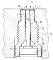
- 10 is the housing of a pressure sensor 11 for determination of the pressure in the combustion chamber of an internal combustion engine. It has a central, continuous, stepped bore 12.
- the opening 13 of the housing 10 facing the combustion chamber is closed by a membrane 14 completed.
- the membrane 14 is in the range of Edge welded to the end face 15 of the housing 10.
- a stamp 18 with one end, the one with the other end acts on a measuring element 19.
- Can as a measuring element e.g. piezoresistive elements or also piezoelectric elements be used. Piezoresistive elements include elements understand that change their resistance value under pressure. Thick film resistors can be used for this purpose, for example.
- Cermet, contactivplastic or metal can be used as materials etc. find use.
- the measuring element 19 is in turn on a Counter bearing 20, which is inserted into the bore 12 and with the Housing is firmly connected.
- Carriers can, not shown in the figure, electrical components be applied to an evaluation device.
- Bores in the counter bearing 20 can be the discharge lines of the evaluation circuit or the measuring element 19 from the housing 10 of the pressure transmitter 11 led out and an evaluation circuit, not shown, and Control device of the internal combustion engine are supplied.
- the opening 13 is formed a recess 21 so that the Opening 13 has a stepped shape.
- This gap 23 should be kept as small as possible be a good heat transfer between the housing 10 and the Allow stamp 18. To further increase this heat transfer can improve the gap 23 with a good heat-conducting medium to be filled out. This medium should also be resistant to high temperatures and be long-term stable. For further improvement to achieve the thermal conductivity, which can be in the range of Opening 13 located annular recess 21 between the housing 10 and the membrane 14 also with a good heat conductivity Medium to be filled out.
- the housing 10 and the stamp 18, ie the force transmission elements are made of materials with the same thermal time constant.
- An essential part of the thermal time constant is the quotient Density x specific heat capacity Thermal conductivity
- the pressure sensor 11 can be screwed into the combustion chamber wall 29.
- the one from the Combustion chamber heat flowing into the housing 10 of the pressure sensor 11 flows to a large extent via the housing 10 on the wall 29 sensor seat and the thread flanks 28 in the wall 29 of the combustion chamber and from there to a heat sink, i.e. a heat dissipation.
- a smaller part of the heat flow flows through the membrane 14, the stamp 18, the counter bearing 20, the housing 10 and in the area of the thread 28 also in the wall 29 and thus also to the heat sink mentioned above.
- the materials should each be from a family of materials.
- the expansion coefficient of the respective material for the housing and for the Stamp 18 deviate slightly from each other, for example different Expansion coefficients for the measuring element 10 and for the counter bearing 20 to be able to compensate.
- the measuring effect can also be improved in that the Membrane 14 is relatively thin and due to the recess 21 has good mobility.
- the membrane 14 should therefore be thin to have a low axial rigidity to be able to.
- the membrane 14 also has at the same time the task of a bias spring, due to which the transmission force connection biased between the membrane, the stamp and the measuring element becomes.
Landscapes
- Physics & Mathematics (AREA)
- General Physics & Mathematics (AREA)
- Measuring Fluid Pressure (AREA)
Applications Claiming Priority (3)
| Application Number | Priority Date | Filing Date | Title |
|---|---|---|---|
| DE4319197 | 1993-06-09 | ||
| DE4319197A DE4319197A1 (de) | 1993-06-09 | 1993-06-09 | Druckgeber zur Druckerfassung im Brennraum von Brennkraftmaschinen |
| PCT/DE1994/000550 WO1994029687A1 (de) | 1993-06-09 | 1994-05-13 | Druckgeber zur druckerfassung im brennraum von brennkraftmaschinen |
Publications (2)
| Publication Number | Publication Date |
|---|---|
| EP0702784A1 EP0702784A1 (de) | 1996-03-27 |
| EP0702784B1 true EP0702784B1 (de) | 1998-03-18 |
Family
ID=6490016
Family Applications (1)
| Application Number | Title | Priority Date | Filing Date |
|---|---|---|---|
| EP94915026A Expired - Lifetime EP0702784B1 (de) | 1993-06-09 | 1994-05-13 | Druckgeber zur druckerfassung im brennraum von brennkraftmaschinen |
Country Status (5)
| Country | Link |
|---|---|
| EP (1) | EP0702784B1 (ja) |
| JP (1) | JP3609829B2 (ja) |
| KR (1) | KR100347642B1 (ja) |
| DE (2) | DE4319197A1 (ja) |
| WO (1) | WO1994029687A1 (ja) |
Cited By (1)
| Publication number | Priority date | Publication date | Assignee | Title |
|---|---|---|---|---|
| AT503664B1 (de) * | 2006-04-13 | 2007-12-15 | Piezocryst Advanced Sensorics | Piezoelektrischer drucksensor |
Families Citing this family (4)
| Publication number | Priority date | Publication date | Assignee | Title |
|---|---|---|---|---|
| DE10108051C2 (de) * | 2001-02-20 | 2003-04-03 | Siemens Ag | Vorrichtung zum Messen des Verbrennungsdruckes |
| JP4638659B2 (ja) * | 2003-05-21 | 2011-02-23 | 株式会社豊田中央研究所 | 圧力センサ |
| JP2006250614A (ja) * | 2005-03-09 | 2006-09-21 | Denso Corp | 圧力検出装置 |
| JP6526467B2 (ja) * | 2015-04-16 | 2019-06-05 | 株式会社ミクニ | 圧力センサ |
Family Cites Families (3)
| Publication number | Priority date | Publication date | Assignee | Title |
|---|---|---|---|---|
| NL7015908A (ja) * | 1970-10-29 | 1972-05-03 | ||
| AT374922B (de) * | 1979-08-09 | 1984-06-12 | List Hans | Messanordner mit einem druckgeber zum messen des druckes heisser medien |
| DE58904807D1 (de) * | 1989-04-28 | 1993-07-29 | Siemens Ag | Halterung fuer das piezoelektrische roehrchen eines drucksensors. |
-
1993
- 1993-06-09 DE DE4319197A patent/DE4319197A1/de not_active Withdrawn
-
1994
- 1994-05-13 WO PCT/DE1994/000550 patent/WO1994029687A1/de not_active Ceased
- 1994-05-13 DE DE59405485T patent/DE59405485D1/de not_active Expired - Fee Related
- 1994-05-13 EP EP94915026A patent/EP0702784B1/de not_active Expired - Lifetime
- 1994-05-13 JP JP50117095A patent/JP3609829B2/ja not_active Expired - Fee Related
- 1994-05-13 KR KR1019950702990A patent/KR100347642B1/ko not_active Expired - Fee Related
Cited By (1)
| Publication number | Priority date | Publication date | Assignee | Title |
|---|---|---|---|---|
| AT503664B1 (de) * | 2006-04-13 | 2007-12-15 | Piezocryst Advanced Sensorics | Piezoelektrischer drucksensor |
Also Published As
| Publication number | Publication date |
|---|---|
| JP3609829B2 (ja) | 2005-01-12 |
| KR100347642B1 (ko) | 2002-11-07 |
| EP0702784A1 (de) | 1996-03-27 |
| DE59405485D1 (de) | 1998-04-23 |
| JPH08511100A (ja) | 1996-11-19 |
| KR960700444A (ko) | 1996-01-20 |
| DE4319197A1 (de) | 1994-12-15 |
| WO1994029687A1 (de) | 1994-12-22 |
Similar Documents
| Publication | Publication Date | Title |
|---|---|---|
| DE69111337T2 (de) | Druckmassfühler. | |
| DE3839515C2 (de) | Druckfühler | |
| DE19538854C1 (de) | Druckgeber zur Druckerfassung im Brennraum von Brennkraftmaschinen | |
| EP0407397B1 (de) | Druckgeber zur druckerfassung im brennraum von brennkraftmaschinen | |
| EP0495935B1 (de) | Verfahren zur herstellung eines druckgebers zur druckerfassung im brennraum von brennkraftmaschinen | |
| DE19919398B4 (de) | Wärmeempfindlicher Flußratensensor | |
| DE4103706A1 (de) | Druckgeber zur druckerfassung im brennraum von brennkraftmaschinen | |
| DE19801484A1 (de) | Meßelement und damit ausgerüsteter Luftmassenmesser | |
| EP1076767B1 (de) | Mikroventil | |
| DE2906965A1 (de) | Drucksensor fuer elektronische steuerungssysteme in kraftfahrzeugmotoren | |
| EP0801150A2 (de) | Elektronisches Bauelement | |
| EP0082151A1 (de) | Sensor | |
| EP0526600B1 (de) | Druckgeber zur druckerfassung im brennraum von brennkraftmaschinen | |
| EP0995979B1 (de) | Druckaufnehmer | |
| WO1992001912A1 (de) | Druckgeber zur druckerfassung im brennraum von brennkraftmaschinen | |
| EP0702784B1 (de) | Druckgeber zur druckerfassung im brennraum von brennkraftmaschinen | |
| DE102007012060A1 (de) | Sensoranordnung zur Druckmessung | |
| DE10063070A1 (de) | Flußsensor des Wärmeerzeugungstyps | |
| DE102006010804A1 (de) | Hochtemperatur-Drucksensorelement, insbesondere zur Messung von Drücken innerhalb von Triebwerken, Verfahren zu dessen Herstellung und Bauteil für Triebwerke | |
| DE4439222A1 (de) | Massenflußsensor mit Druckkompensation | |
| WO1991019966A1 (de) | Druck- und wärmefluss-sensor für den verbrennungsraum von verbrennungsmotoren | |
| DE102007015476A1 (de) | Druckübertragungsmedium und Verfahren zu seiner Herstellung | |
| DE10101351C2 (de) | Sensorelement | |
| EP0508249B1 (de) | Drucksensor | |
| DE4332539A1 (de) | Druckgeber zur Druckerfassung im Brennraum von Brennkraftmaschinen |
Legal Events
| Date | Code | Title | Description |
|---|---|---|---|
| PUAI | Public reference made under article 153(3) epc to a published international application that has entered the european phase |
Free format text: ORIGINAL CODE: 0009012 |
|
| 17P | Request for examination filed |
Effective date: 19960109 |
|
| AK | Designated contracting states |
Kind code of ref document: A1 Designated state(s): DE FR GB IT SE |
|
| 17Q | First examination report despatched |
Effective date: 19970227 |
|
| GRAG | Despatch of communication of intention to grant |
Free format text: ORIGINAL CODE: EPIDOS AGRA |
|
| GRAG | Despatch of communication of intention to grant |
Free format text: ORIGINAL CODE: EPIDOS AGRA |
|
| GRAG | Despatch of communication of intention to grant |
Free format text: ORIGINAL CODE: EPIDOS AGRA |
|
| GRAH | Despatch of communication of intention to grant a patent |
Free format text: ORIGINAL CODE: EPIDOS IGRA |
|
| GRAH | Despatch of communication of intention to grant a patent |
Free format text: ORIGINAL CODE: EPIDOS IGRA |
|
| GRAA | (expected) grant |
Free format text: ORIGINAL CODE: 0009210 |
|
| AK | Designated contracting states |
Kind code of ref document: B1 Designated state(s): DE FR GB IT SE |
|
| ET | Fr: translation filed | ||
| REF | Corresponds to: |
Ref document number: 59405485 Country of ref document: DE Date of ref document: 19980423 |
|
| ITF | It: translation for a ep patent filed | ||
| GBT | Gb: translation of ep patent filed (gb section 77(6)(a)/1977) |
Effective date: 19980520 |
|
| PLBE | No opposition filed within time limit |
Free format text: ORIGINAL CODE: 0009261 |
|
| STAA | Information on the status of an ep patent application or granted ep patent |
Free format text: STATUS: NO OPPOSITION FILED WITHIN TIME LIMIT |
|
| 26N | No opposition filed | ||
| REG | Reference to a national code |
Ref country code: GB Ref legal event code: IF02 |
|
| PGFP | Annual fee paid to national office [announced via postgrant information from national office to epo] |
Ref country code: SE Payment date: 20060524 Year of fee payment: 13 |
|
| PGFP | Annual fee paid to national office [announced via postgrant information from national office to epo] |
Ref country code: DE Payment date: 20070726 Year of fee payment: 14 |
|
| EUG | Se: european patent has lapsed | ||
| PG25 | Lapsed in a contracting state [announced via postgrant information from national office to epo] |
Ref country code: SE Free format text: LAPSE BECAUSE OF NON-PAYMENT OF DUE FEES Effective date: 20070514 |
|
| PGFP | Annual fee paid to national office [announced via postgrant information from national office to epo] |
Ref country code: IT Payment date: 20080524 Year of fee payment: 15 |
|
| PGFP | Annual fee paid to national office [announced via postgrant information from national office to epo] |
Ref country code: GB Payment date: 20080522 Year of fee payment: 15 |
|
| PG25 | Lapsed in a contracting state [announced via postgrant information from national office to epo] |
Ref country code: DE Free format text: LAPSE BECAUSE OF NON-PAYMENT OF DUE FEES Effective date: 20081202 |
|
| GBPC | Gb: european patent ceased through non-payment of renewal fee |
Effective date: 20090513 |
|
| REG | Reference to a national code |
Ref country code: FR Ref legal event code: ST Effective date: 20100129 |
|
| PG25 | Lapsed in a contracting state [announced via postgrant information from national office to epo] |
Ref country code: FR Free format text: LAPSE BECAUSE OF NON-PAYMENT OF DUE FEES Effective date: 20090602 |
|
| PGFP | Annual fee paid to national office [announced via postgrant information from national office to epo] |
Ref country code: FR Payment date: 20080519 Year of fee payment: 15 |
|
| PG25 | Lapsed in a contracting state [announced via postgrant information from national office to epo] |
Ref country code: GB Free format text: LAPSE BECAUSE OF NON-PAYMENT OF DUE FEES Effective date: 20090513 |
|
| PG25 | Lapsed in a contracting state [announced via postgrant information from national office to epo] |
Ref country code: IT Free format text: LAPSE BECAUSE OF NON-PAYMENT OF DUE FEES Effective date: 20090513 |