EP0702804B1 - Dispositif d'amplification de taux de modulation d'amplitude d'un faisceau optique - Google Patents
Dispositif d'amplification de taux de modulation d'amplitude d'un faisceau optique Download PDFInfo
- Publication number
- EP0702804B1 EP0702804B1 EP95914431A EP95914431A EP0702804B1 EP 0702804 B1 EP0702804 B1 EP 0702804B1 EP 95914431 A EP95914431 A EP 95914431A EP 95914431 A EP95914431 A EP 95914431A EP 0702804 B1 EP0702804 B1 EP 0702804B1
- Authority
- EP
- European Patent Office
- Prior art keywords
- frequency
- wave
- optical
- arm
- arms
- Prior art date
- Legal status (The legal status is an assumption and is not a legal conclusion. Google has not performed a legal analysis and makes no representation as to the accuracy of the status listed.)
- Expired - Lifetime
Links
- 230000003287 optical effect Effects 0.000 title claims description 53
- 230000003321 amplification Effects 0.000 title claims description 10
- 238000003199 nucleic acid amplification method Methods 0.000 title claims description 10
- 230000010363 phase shift Effects 0.000 description 7
- 230000000694 effects Effects 0.000 description 2
- 230000005684 electric field Effects 0.000 description 2
- 241001080024 Telles Species 0.000 description 1
- 238000010009 beating Methods 0.000 description 1
- 238000001514 detection method Methods 0.000 description 1
- 238000010586 diagram Methods 0.000 description 1
- 230000009977 dual effect Effects 0.000 description 1
- 238000000034 method Methods 0.000 description 1
- 230000001902 propagating effect Effects 0.000 description 1
- 238000005215 recombination Methods 0.000 description 1
- 230000006798 recombination Effects 0.000 description 1
Images


Classifications
-
- G—PHYSICS
- G02—OPTICS
- G02F—OPTICAL DEVICES OR ARRANGEMENTS FOR THE CONTROL OF LIGHT BY MODIFICATION OF THE OPTICAL PROPERTIES OF THE MEDIA OF THE ELEMENTS INVOLVED THEREIN; NON-LINEAR OPTICS; FREQUENCY-CHANGING OF LIGHT; OPTICAL LOGIC ELEMENTS; OPTICAL ANALOGUE/DIGITAL CONVERTERS
- G02F2/00—Demodulating light; Transferring the modulation of modulated light; Frequency-changing of light
- G02F2/02—Frequency-changing of light, e.g. by quantum counters
-
- G—PHYSICS
- G02—OPTICS
- G02F—OPTICAL DEVICES OR ARRANGEMENTS FOR THE CONTROL OF LIGHT BY MODIFICATION OF THE OPTICAL PROPERTIES OF THE MEDIA OF THE ELEMENTS INVOLVED THEREIN; NON-LINEAR OPTICS; FREQUENCY-CHANGING OF LIGHT; OPTICAL LOGIC ELEMENTS; OPTICAL ANALOGUE/DIGITAL CONVERTERS
- G02F1/00—Devices or arrangements for the control of the intensity, colour, phase, polarisation or direction of light arriving from an independent light source, e.g. switching, gating or modulating; Non-linear optics
- G02F1/01—Devices or arrangements for the control of the intensity, colour, phase, polarisation or direction of light arriving from an independent light source, e.g. switching, gating or modulating; Non-linear optics for the control of the intensity, phase, polarisation or colour
- G02F1/21—Devices or arrangements for the control of the intensity, colour, phase, polarisation or direction of light arriving from an independent light source, e.g. switching, gating or modulating; Non-linear optics for the control of the intensity, phase, polarisation or colour by interference
- G02F1/225—Devices or arrangements for the control of the intensity, colour, phase, polarisation or direction of light arriving from an independent light source, e.g. switching, gating or modulating; Non-linear optics for the control of the intensity, phase, polarisation or colour by interference in an optical waveguide structure
Definitions
- the field of the invention is that of optical systems requiring amplitude modulation and in particular at cadences microwave.
- the problems often encountered is that of ratio between the electrical power PE, used to effect the modulation amplitude and the electrical power PS supplied by a photodetector capable of detecting the modulated optical wave.
- This aspect is particularly important in the microwave domain and moreover in this case the modulation signal is of the analog type which leads to performing a modulation with a modulation rate lower than 1, to preserve the signal quality.
- the power generated by the photodetector is then relatively small.
- an optical amplifier can be used before detection by a photodetector, to increase the optical signal. It is also possible to use a high power laser source and a external modulator.
- the optical amplifier and the photodetector may strongly to saturate by receiving not only optical power modulated but also the continuous background resulting from a modulation rate less than 1.
- Optical power is not judiciously used since it is present not only on the important signal (signal modulated) but also on a continuous background useless for the application.
- the present invention provides a device amplification of amplitude modulation rate of an optical beam capable of eliminating the continuous background present in a modulated signal.
- the device according to the invention comprises means making it possible to make interfere with two optical waves of the same amplitude at frequencies offset and thereby obtain a purely sinusoidal optical wave without continuous background.
- the modulation rate amplification device can also include a Mach Zehnder interferometer, each arms comprising a phase shifter, a phase shifter being continuous and creating a phase shift of ⁇ , the other phase shifter creating a sinusoidal phase shift with a frequency hyper.
- a Mach Zehnder interferometer each arms comprising a phase shifter, a phase shifter being continuous and creating a phase shift of ⁇ , the other phase shifter creating a sinusoidal phase shift with a frequency hyper.
- the interferometric device there is mainly interference between two optical waves of the same amplitude at frequencies FL - FM and FL + FM respectively.
- the invention also relates to a rate amplification device modulation in which the interferometric device is a Sagnac microinterferometer into which a phase shifter is introduced microwave. At the output of this interferometric device we arrive also to make two optical waves of the same amplitude interfere shifted by a frequency 2FM, if the phase shifter is supplied at the frequency FM.
- the interferometric device is a Sagnac microinterferometer into which a phase shifter is introduced microwave.
- the device according to the invention must ensure the interference of two waves shifted by a frequency in microwave, of the same amplitude to provide an optical signal modulated in microwave and having no continuous background, this signal can then advantageously be optically amplified and then detected by a photodetector.
- a first configuration uses an interferometric device comprising on the one hand a frequency translator, on the other hand a phase shifter; the general principle of such a configuration will be better understood by considering the general diagram of FIG. 1.
- a laser source emitting continuously and assumed to be monofrequency and emitting optical power PO is coupled in a two-wave interferometric device.
- a frequency translator Tf supplied by a microwave power PE.
- This frequency translator generates from an incident optical wave at frequency FL, a wave at frequency FL + FM and a wave at frequency FL (FM being the frequency of the microwave wave coming from a generator delivering the power PE).
- the ratio between the translated wave of frequency FL + FM and the non-translated wave FL depends on the amplitude of the microwave signal applied. Insofar as it is sought to reduce the power PE, this ratio is necessarily low. This is why in the second arm B 2 , there is a phase shifter D ⁇ , operating continuously, the value of which is adjusted so that, after recombination of the two arms, the two waves at FL and FL + FM have the same amplitude.
- the dual-frequency optical signal then passes through an optical amplifier AO, of gain G, before being sent to the photodetector which finally analyzes the beat between the two waves of different frequencies, to supply a signal at the FM frequency.
- the detected signal is not only consist of a component at the resulting FM frequency of the beating of the two optical waves of different frequencies but also of the continuous background due to the fact that the two waves are not same amplitude.
- the action of the interferometer using a translator of frequency and a phase shifter is therefore to remove the continuous background and not leave only the beat between the beat signal between two waves of the same amplitude and therefore with a contrast of 1.
- the optical amplifier AO thus only amplifies the optical signal useful and the photodetector is not likely to be limited by the continuous background. We can thus take advantage of all the maximum output power of the amplifier optical acceptable by the photodetector.
- the translator Tf of the arm B 1 can advantageously be an acoustooptic device of the acoustooptic deflector type supplied with microwave.
- This acoustooptical deflector may include a piezoelectric transducer capable of generating an acoustic wave which, by creating an index network structure, will shift in frequency an incident optical wave at the frequency FL, by a difference in frequency of FM.
- the translator Tf can also be an electrooptical device. An electric field is generated by means of electrodes which will initiate propagation of a microwave wave.
- This phase shifter D ⁇ o can typically consist of a guide comprised between two electrodes so as to apply a continuous electric field, influencing the optical index and therefore the optical path of the incident wave so as to obtain the desired phase shift.
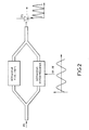
- the interferometric device can advantageously comprise two phase shifters, as illustrated in FIG. 2.
- a first phase shifter D ⁇ induces a phase shift of a value of ⁇ on the wave incident optics.
- a phase shifter D FM can be introduced, electrically supplied at the frequency FM / 2.
- a series of optical waves is then generated at frequencies FL ⁇ FM / 2; FL ⁇ 3 FM / 2, ... with mainly two preponderant components FL + FM / 2 and FL - FM / 2.
- interference is mainly obtained between microwave waves at frequencies + FM / 2 and - FM / 2 and therefore indeed a dual frequency optical wave with equal amplitudes for the two components and without continuous background after beat.
- a third configuration of interferometric device, used in the device according to the invention is a Sagnac microinterferometer such as shown in Figure 3.
- the optical wave at frequency FL is divided by a separating plate in two waves which propagate in opposite directions the along a closed path defined by mirrors.
- These two counter-propagating waves recombine and produce interference fringes can be detected by a photodetector placed in point 1. When no non-reciprocal effect is introduced in the closed path, the two counter-propagating waves arrive in phase opposition at point 1.
Landscapes
- Physics & Mathematics (AREA)
- Nonlinear Science (AREA)
- General Physics & Mathematics (AREA)
- Optics & Photonics (AREA)
- Optical Modulation, Optical Deflection, Nonlinear Optics, Optical Demodulation, Optical Logic Elements (AREA)
- Instruments For Measurement Of Length By Optical Means (AREA)
- Lasers (AREA)
Description
- un dispositif interférométrique à deux bras B1 et B2, chaque bras recevant une partie de l'onde incidente, l'un des bras étant également alimenté par un dispositif électrique capable de créer une onde hyperfréquence à la fréquence FM au sein dudit bras,
- ce dispositif interférométrique comprenant des moyens pour
générer en sortie des deux bras, deux ondes optiques de même amplitude,
décalées en fréquence, caractérisé en ce que :
- - le bras B1 comporte un translateur de fréquence Tf, commandé par une onde hyperfréquence à la fréquence FM et fournissant en sortie une onde optique à la fréquence FL et une onde optique à la fréquence FM + FL, respectivement d'amplitude a1(FL) et a'1(FM + FL),
- - le bras B2 comportant un déphaseur continu D procurant en sortie une onde optique à la fréquence FL d'amplitude a2(FL) telle, que recombinée en sortie du dispositif interférométrique, à l'onde optique d'amplitude a1(FL) il en résulte une onde optique d'amplitude a'1(FL).
- la figure 1 illustre un exemple de dispositif selon l'invention utilisant un translateur de fréquence Tf;
- la figure 2 illustre un autre exemple de dispositif selon l'invention utilisant un interféromètre avec deux déphaseurs, un continu et un alimenté en hyperfréquence ;
- la figure 3 illustre un troisième exemple de dispositif selon l'invention comprenant un microinterféromètre de Sagnac.
Claims (6)
- Dispositif d'amplification de taux de modulation d'une onde optique incidente monofréquence, de fréquence FL comprenant un amplificateur optique AO, comprenant entre l'onde incidente et l'amplificateur :un dispositif interférométrique à deux bras B1 et B2, chaque bras recevant une partie de l'onde incidente, l'un des bras étant également alimenté par un dispositif électrique capable de créer une onde hyperfréquence à la fréquence FM au sein dudit bras,ce dispositif interférométrique comprenant des moyens pour générer en sortie des deux bras, deux ondes optiques de même amplitude, décalées en fréquence caractérisé en ce que :- le bras B1 comporte un translateur de fréquence Tf, commandé par une onde hyperfréquence à la fréquence FM et foumissant en sortie une onde optique à la fréquence FL et une onde optique à la fréquence FM + FL, respectivement d'amplitude a1(FL) et a'1(FM + FL),- le bras B2 comporte un déphaseur continu D procurant en sortie une onde optique à la fréquence FL d'amplitude a2(FL) telle, que recombinée en sortie du dispositif interférométrique, à l'onde optique d'amplitude a1(FL) il en résulte une onde optique d'amplitude a'1(FL).
- Dispositif d'amplification de taux de modulation selon la revendication 1, caractérisé en ce que le translateur de fréquence est un dispositif acoustooptique.
- Dispositif d'amplification de taux de modulation selon la revendication 1, caractérisé en ce que le translateur de fréquence est un dispositif électrooptique.
- Dispositif d'amplification de taux de modulation selon la revendication 2, caractérisé en ce que le translateur de fréquence est un déflecteur acoustooptique.
- Dispositif d'amplification de taux de modulation d'une onde optique incidente monofréquence, de fréquence FL comprenant un amplificateur optique AO, comprenant entre l'onde incidente et l'amplificateur :un dispositif interférométrique à deux bras B1 et B2, chaque bras recevant une partie de l'onde incidente, l'un des bras étant également alimenté par un dispositif électrique capable de créer une onde hyperfréquence à la fréquence FM au sein dudit bras,ce dispositif interférométrique comprenant des moyens pour générer en sortie des deux bras, deux ondes optiques de même amplitude, décalées en fréquence, caractérisé en ce que le bras B1 comprend un déphaseur fixe de π, le bras B2 comprenant un déphaseur alimenté en hyperfréquence.
- Dispositif d'amplification de taux de modulation d'une onde optique incidente monofréquence, de fréquence FL comprenant un amplificateur optique AO, comprenant entre l'onde incidente et l'amplificateur :un dispositif interférométrique à deux bras B1 et B2, chaque bras recevant une partie de l'onde incidente, l'un des bras étant également alimenté par un dispositif électrique capable de créer une onde hyperfréquence à la fréquence FM au sein dudit bras,ce dispositif interférométrique comprenant des moyens pour générer en sortie des deux bras, deux ondes optiques de même amplitude, décalées en fréquence, caractérisé en ce que le dispositif interférométrique est un microinterféromètre de Sagnac comprenant un déphaseur alimenté en hyperfréquence D2.
Applications Claiming Priority (3)
| Application Number | Priority Date | Filing Date | Title |
|---|---|---|---|
| FR9404167A FR2718539B1 (fr) | 1994-04-08 | 1994-04-08 | Dispositif d'amplification de taux de modulation d'amplitude d'un faisceau optique. |
| FR9404167 | 1994-04-08 | ||
| PCT/FR1995/000386 WO1995027921A1 (fr) | 1994-04-08 | 1995-03-28 | Dispositif d'amplification de taux de modulation d'amplitude d'un faisceau optique |
Publications (2)
| Publication Number | Publication Date |
|---|---|
| EP0702804A1 EP0702804A1 (fr) | 1996-03-27 |
| EP0702804B1 true EP0702804B1 (fr) | 2001-06-20 |
Family
ID=9461893
Family Applications (1)
| Application Number | Title | Priority Date | Filing Date |
|---|---|---|---|
| EP95914431A Expired - Lifetime EP0702804B1 (fr) | 1994-04-08 | 1995-03-28 | Dispositif d'amplification de taux de modulation d'amplitude d'un faisceau optique |
Country Status (5)
| Country | Link |
|---|---|
| US (1) | US5835258A (fr) |
| EP (1) | EP0702804B1 (fr) |
| DE (1) | DE69521382T2 (fr) |
| FR (1) | FR2718539B1 (fr) |
| WO (1) | WO1995027921A1 (fr) |
Families Citing this family (6)
| Publication number | Priority date | Publication date | Assignee | Title |
|---|---|---|---|---|
| JP3567759B2 (ja) | 1998-09-28 | 2004-09-22 | 株式会社村田製作所 | 誘電体セラミック組成物および積層セラミックコンデンサ |
| FR2784185B1 (fr) | 1998-10-06 | 2001-02-02 | Thomson Csf | Dispositif pour l'harmonisation entre une voie d'emission laser et une voie passive d'observation |
| US7106491B2 (en) * | 2001-12-28 | 2006-09-12 | Texas Instruments Incorporated | Split beam micromirror |
| US20040024598A1 (en) * | 2002-07-03 | 2004-02-05 | Amit Srivastava | Thematic segmentation of speech |
| US6958846B2 (en) * | 2002-11-26 | 2005-10-25 | Reflectivity, Inc | Spatial light modulators with light absorbing areas |
| WO2019202602A1 (fr) * | 2018-04-19 | 2019-10-24 | Ariel Scientific Innovations Ltd. | Procédé et système d'interférométrie |
Family Cites Families (7)
| Publication number | Priority date | Publication date | Assignee | Title |
|---|---|---|---|---|
| CA2011954C (fr) * | 1989-03-14 | 1994-02-22 | Fujitsu Limited | Modulateur optique |
| US5144468A (en) * | 1989-06-16 | 1992-09-01 | Honeywell Inc. | Mixing interferometer used as a communications link |
| FR2669126B1 (fr) * | 1990-11-09 | 1993-01-22 | Thomson Csf | Systeme de visualisation d'images fournies par un modulateur spatial avec transfert d'energie. |
| FR2671237B1 (fr) * | 1990-12-28 | 1995-03-31 | Thomson Csf | Laser solide de grande energie. |
| US5199086A (en) * | 1991-01-17 | 1993-03-30 | Massachusetts Institute Of Technology | Electro-optic system |
| FR2678455B1 (fr) * | 1991-06-27 | 1993-09-03 | Thomson Csf | Dispositif de modulation electrooptique integre. |
| FR2686431A1 (fr) * | 1992-01-21 | 1993-07-23 | Thomson Csf | Doubleur de frequence optique utilisant des structures quantiques semiconductrices. |
-
1994
- 1994-04-08 FR FR9404167A patent/FR2718539B1/fr not_active Expired - Fee Related
-
1995
- 1995-03-28 EP EP95914431A patent/EP0702804B1/fr not_active Expired - Lifetime
- 1995-03-28 US US08/549,813 patent/US5835258A/en not_active Expired - Fee Related
- 1995-03-28 WO PCT/FR1995/000386 patent/WO1995027921A1/fr not_active Ceased
- 1995-03-28 DE DE69521382T patent/DE69521382T2/de not_active Expired - Fee Related
Also Published As
| Publication number | Publication date |
|---|---|
| WO1995027921A1 (fr) | 1995-10-19 |
| US5835258A (en) | 1998-11-10 |
| DE69521382D1 (de) | 2001-07-26 |
| FR2718539B1 (fr) | 1996-04-26 |
| EP0702804A1 (fr) | 1996-03-27 |
| DE69521382T2 (de) | 2001-10-31 |
| FR2718539A1 (fr) | 1995-10-13 |
Similar Documents
| Publication | Publication Date | Title |
|---|---|---|
| US8144334B2 (en) | Fiber-optic, digital system for laser Doppler vibrometers (LDVs) | |
| EP0297338B1 (fr) | Système interférométrique à fibre optique de type sagnac | |
| US20050078316A1 (en) | Active coherence reduction for interferometer interrogation | |
| EP0030891B1 (fr) | Procédé et dispositif de mesure de la différence de phase des ondes circulant dans un interféromètre en anneau | |
| Azmi et al. | Fiber laser based hydrophone systems | |
| US6559946B2 (en) | Method and apparatus to minimize effects of ASE in optical measurements | |
| EP3698465B1 (fr) | Oscillateur radiofrequence ameliore | |
| EP3353502A1 (fr) | Systeme de mesure et capteur de temperature et/ou de deformation par analyse de retroreflexion brillouin. | |
| FR2645264A1 (fr) | Gyroscope a fibre optique | |
| FR2759790A1 (fr) | Convertisseur de longueur d'onde de signaux optiques binaires | |
| EP0702804B1 (fr) | Dispositif d'amplification de taux de modulation d'amplitude d'un faisceau optique | |
| JP3408789B2 (ja) | 後方散乱光の測定方法およびその装置 | |
| EP0141739B1 (fr) | Dispositif interférométrique de mesure d'une vitesse de rotation angulaire | |
| JP2004226093A (ja) | レーザ振動計 | |
| FR2662805A1 (fr) | Capteur de rotation optique a fibre. | |
| JP3538619B2 (ja) | 光変調器の特性評価方法、およびそれを用いた高周波発振装置の制御方法 | |
| JP3152314B2 (ja) | 後方散乱光の測定方法およびその装置 | |
| FR2686163A1 (fr) | Procede de linearisation de la fonction de transmission d'un modulateur. | |
| EP0099282A1 (fr) | Dispositif optique intégré modulateur indépendant de la polarisation incidente | |
| EP2368298B1 (fr) | Système laser muni d'un asservissement de fréquence | |
| EP4310457A1 (fr) | Système de capteur à fibre optique distribué | |
| Li et al. | Optical frequency shifter on SOI using thermo-optic serrodyne modulation | |
| EP4367475A1 (fr) | Interféromètre à fibre optique basé sur une source laser monofréquence et procédé d'interférométrie corrigés des réflexions parasites | |
| EP0668672A1 (fr) | Système de communication optique à brouilleur de polarisation | |
| EP0421880B1 (fr) | Composant polyvalent d'optique intégrée et réseau de distribution avec amplification optique |
Legal Events
| Date | Code | Title | Description |
|---|---|---|---|
| PUAI | Public reference made under article 153(3) epc to a published international application that has entered the european phase |
Free format text: ORIGINAL CODE: 0009012 |
|
| 17P | Request for examination filed |
Effective date: 19951128 |
|
| AK | Designated contracting states |
Kind code of ref document: A1 Designated state(s): DE GB |
|
| 17Q | First examination report despatched |
Effective date: 19980217 |
|
| GRAG | Despatch of communication of intention to grant |
Free format text: ORIGINAL CODE: EPIDOS AGRA |
|
| GRAG | Despatch of communication of intention to grant |
Free format text: ORIGINAL CODE: EPIDOS AGRA |
|
| GRAG | Despatch of communication of intention to grant |
Free format text: ORIGINAL CODE: EPIDOS AGRA |
|
| GRAH | Despatch of communication of intention to grant a patent |
Free format text: ORIGINAL CODE: EPIDOS IGRA |
|
| GRAH | Despatch of communication of intention to grant a patent |
Free format text: ORIGINAL CODE: EPIDOS IGRA |
|
| GRAA | (expected) grant |
Free format text: ORIGINAL CODE: 0009210 |
|
| AK | Designated contracting states |
Kind code of ref document: B1 Designated state(s): DE GB |
|
| REF | Corresponds to: |
Ref document number: 69521382 Country of ref document: DE Date of ref document: 20010726 |
|
| GBT | Gb: translation of ep patent filed (gb section 77(6)(a)/1977) |
Effective date: 20010906 |
|
| RAP2 | Party data changed (patent owner data changed or rights of a patent transferred) |
Owner name: THALES |
|
| REG | Reference to a national code |
Ref country code: GB Ref legal event code: IF02 |
|
| PLBE | No opposition filed within time limit |
Free format text: ORIGINAL CODE: 0009261 |
|
| STAA | Information on the status of an ep patent application or granted ep patent |
Free format text: STATUS: NO OPPOSITION FILED WITHIN TIME LIMIT |
|
| 26N | No opposition filed | ||
| PGFP | Annual fee paid to national office [announced via postgrant information from national office to epo] |
Ref country code: GB Payment date: 20050323 Year of fee payment: 11 |
|
| PGFP | Annual fee paid to national office [announced via postgrant information from national office to epo] |
Ref country code: DE Payment date: 20050324 Year of fee payment: 11 |
|
| PG25 | Lapsed in a contracting state [announced via postgrant information from national office to epo] |
Ref country code: GB Free format text: LAPSE BECAUSE OF NON-PAYMENT OF DUE FEES Effective date: 20060328 |
|
| PG25 | Lapsed in a contracting state [announced via postgrant information from national office to epo] |
Ref country code: DE Free format text: LAPSE BECAUSE OF NON-PAYMENT OF DUE FEES Effective date: 20061003 |
|
| GBPC | Gb: european patent ceased through non-payment of renewal fee |
Effective date: 20060328 |