EP0702923A2 - Pare-douche - Google Patents
Pare-douche Download PDFInfo
- Publication number
- EP0702923A2 EP0702923A2 EP95114765A EP95114765A EP0702923A2 EP 0702923 A2 EP0702923 A2 EP 0702923A2 EP 95114765 A EP95114765 A EP 95114765A EP 95114765 A EP95114765 A EP 95114765A EP 0702923 A2 EP0702923 A2 EP 0702923A2
- Authority
- EP
- European Patent Office
- Prior art keywords
- drip
- splash guard
- frame
- guard according
- holding frame
- Prior art date
- Legal status (The legal status is an assumption and is not a legal conclusion. Google has not performed a legal analysis and makes no representation as to the accuracy of the status listed.)
- Withdrawn
Links
Images


Classifications
-
- A—HUMAN NECESSITIES
- A47—FURNITURE; DOMESTIC ARTICLES OR APPLIANCES; COFFEE MILLS; SPICE MILLS; SUCTION CLEANERS IN GENERAL
- A47K—SANITARY EQUIPMENT; ACCESSORIES THEREFOR, e.g. TOILET ACCESSORIES
- A47K3/00—Baths; Showers; Appurtenances therefor
- A47K3/28—Showers or bathing douches
- A47K3/30—Screens or collapsible cabinets for showers or baths
- A47K3/36—Articulated screens
Definitions
- shower partitions which are designed in the form of fixed or pivotable partitions made of glass or plastic.
- such separating surfaces have frames made of light metal, in which a thin, stiff polystyrene plate is held.
- the frame is used for fastening to a building wall and / or to an adjacent further, for example, pivotable, partition surface.
- the frame also has the task of covering the sharp-edged edge of the thin polystyrene plate in order to avoid the risk of injury here.
- shape it was previously limited because such shower partitions in the floor plan (starting from flat partition surfaces) only allowed polygonal arrangements, or were practically limited to cylindrical surfaces in the case of curved partition surfaces.
- plastics as well as glass, there was only a limited scope for decorating these separating surfaces by appropriate structuring of the surface and / or by printing.
- the invention has for its object to provide a splash guard for a shower, which allows a much freer design both in terms of space and in terms of decor.
- a splash guard for a shower with at least one drip catcher, the edge contour of which is at least partially encompassed by a holding frame which is connected to a building wall, and in which the drip catcher surface consists of a flexible material.
- the drip-catching surface consists of a thin, flexible material which is connected to the holding frame and provided with clamping means.
- Thin plastic films, but in particular also fabrics, can be considered as a thin, flexible material. These are connected to the holding frame at the edge.
- the clamping devices then depend on the given surface design. In the case of flat drip-catching surfaces, it is sufficient if the material is connected to the holding frame at the edge by means of appropriate tensioning and / or fastening means. This can be done, for example, by means of a snap button flap, zippers or the like. The required tension can be achieved by corresponding specifications of the dimensions.
- the clamping means also have the task of maintaining the surface curvature specified by the holding frame within the edge contour specified by the holding frame, so that despite the inherent Given the instability of the thin material used, as is the case with a thin plastic film or a fabric, one or more clamping means nevertheless produce a "stable" surface.
- Another advantage of using such thin, flexible materials is that they can be colored, printed or composed of differently colored webs, so that in addition to the free design of the surface geometry there is also a free design option in terms of decor and color .
- Another advantage is that with a detachable connection of the thin material forming the drip-trapping surface, the drip-trapping surface can be removed from time to time and cleaned or washed, this being possible in particular in the use of fabrics in the washing machine.
- Another advantage is that the drip catcher surface can be replaced in a simple manner, so that a new, differently designed drip catcher surface makes it easy to give the bathroom "a new face" from time to time.
- At least one tensioning rod is provided as the tensioning means, to which the drip-catching surface is connected in a form-fitting manner, preferably releasably.
- the tension rod can be designed to be resilient-flexible or it can also be bent in accordance with the curvature meridian of the drip trapping surface to be stabilized, so that the material of the drip trapping surface can be stretched from within the holding frame, but nevertheless the ones specified by the edge contour of the holding frame, for example spatial Maintain curvature of the drip trapping surface and the desired optical effect can be achieved.
- the tie rod can be buttoned on or attached to the material of the drip trap by means of reefing straps.
- the drip-catching surface can be provided with a push-through pocket for the connection to the tensioning rod.
- the tie rod can also be connected to the holding frame at least with its two free ends.
- the connection can be designed as a plug connection. It is expedient here to use elastic-flexible tension rods so that curvatures of the drip-catching surface can be generated, which are predetermined by the elastic deformation of the clamped tension rod.
- the holding frame is provided on at least one frame spar with a longitudinal undercut groove for the positive reception of the associated edge of the drip catch area.
- the associated edge of the drip trapping surface is provided with a hemstitch into which a plastic wire of appropriate thickness is inserted. If the edge which is thickened in cross section in this way is inserted into the undercut groove, this results in a uniform attachment of the drip catch area to the relevant frame rail over the corresponding length of the frame rail.
- the drip trap surface consists of an elastic, inherently stable, thick, flexible plastic film.
- the holding frame only a vertical frame spar and an associated upper, substantially horizontally extending frame spar and this upper, substantially horizontal frame spar trained curved. If you now clamp a plastic film that is dimensioned in terms of its thickness and elasticity, the drip trap surface is set in a spatially curved surface, the other vertically running edge at least partially and the lower edge of the plastic film without any connection due to the elastic tensioning of the plastic film can be carried out on a holding frame.
- the vertically aligned frame spars are connected to one another by at least one handle bar which extends at a distance across at least one side across the drip catcher surface.
- the handle bar which can also serve as a towel holder, on the one hand protects a drop-catching surface made of thin, flexible material against unwanted contact, and on the other hand improves the manageability of a splash guard pivotally connected to the building wall.
- the dimensional stability of the holding frame is increased, which can be particularly important in the case of a drip catch surface material clamped to the holding frame.
- the splash guard is constructed in several parts, with at least one partial frame being pivotably connected to an adjacent partial frame and that a subframe is connected to the building wall.
- a partial frame can be firmly connected to the wall and the adjoining partial frame can be pivotally connected in a door-like manner.
- the material of the drip trap area spans several, preferably all, sub-frames in one piece. This has the advantage that the material forming the drip trap surface also spans the joint area, so that complicated and complex seals can also be dispensed with in this area.
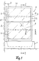
- FIG. 1 shows a side view of a shower tray 1 arranged in a corner of a room.
- a bathtub could also be arranged here, to which a shower head is assigned.
- a splash guard 3 is fastened to the associated building wall 2 via corresponding joints 4.
- the joints 4 are connected to a holding frame 5, the edge contour of which limits a drip trap area 6.
- the holding frame 5 is composed of two vertical and two horizontal tubular frame bars in this embodiment.
- a flexible, waterproof, but at least splash-proof material is connected to the holding frame 5 as a drip-catching surface 6.
- Thin, flexible, elastic or inelastic materials in the form of foils or fabrics can be used. When using fabrics, these can be impregnated or coated to ensure at least splash water tightness.
- the material of the drip trap is tightly connected to the upper horizontal and the two lateral vertical frame bars, while it can overlap the lower horizontal frame bar so that there is a drip edge here.
- the holding frame and the fastening of the material of the drip-catching surface to the holding frame is expediently chosen such that the drip-catching surface runs practically in the plane of the surface of the holding frame which points inward into the area of the shower.
- a splash guard strip 7 is also connected to the wall, which covers the gap 8 between the building wall 2 and the relevant frame member of the holding frame 5.
- the splash guard 7 can also serve as a load-bearing and / or fastening element for the joints 4.
- one or two tensioning rods 9 are provided as clamping means, which ensure a corresponding stabilization of the dripping-catching surface as a whole.
- the tie rods 9 also have the task of maintaining this curvature even in the areas of the drip trap surface 6 which are at a distance from the curved frame spars. It is possible to specify any curvature, one is not limited to the shape of a circular cylinder surface.
- the tie rods 9 can be bent in accordance with the curvature of the upper and lower frame members or it is also possible to provide elastic materials for the tie rods 9, so that the tie rods 9 are each clamped with their free ends in the vertical frame members of the holding frame 5. Variations in the course of the curvature are also possible here, for example by virtue of the fact that the tension rods 9 have different bendability with respect to their length, so that asymmetrical curvature contours can also be produced here.
- the tensioning rods 9 can run on the outside of the drip-catching surface, the material of the dripping-catching surface 6 then being connected to the tensioning rods 9, for example, via “reefing straps”.
- FIG. 2 and FIG. 3 show an advantageous fastening of the drip catcher surface 6 on the holding frame 5 and the connection of the tensioning rods 9 to the drip catcher surface 6.
- the frame bars of the holding frame 5 are tubular, as the section for the upper frame bar 5.1 shows, and provided with an undercut groove 10.1 that is open to the outside.
- the vertical frame spar 5.2 is also provided with a corresponding groove 10.2.
- the material of the drip trap surface 6 is provided at its edge with a hemstitch 11, into which a plastic rod 12 is inserted. Since the groove 10.1 is undercut, there is a positive connection between the edge of the drip catcher surface 6 and the frame spar 5.1.
- the grooves 10 in the frame spars of the holding frame 5 are expediently offset laterally to the central plane 13 of the holding frame 5, so that this positions the Drip trapping surface 6 is possible in the area of the plane defined by the outer surface of the holding frame and thus the drip trapping surface can be moved into the room area 14 facing the shower by this distance from the frame center plane 13.
- This arrangement also makes it possible, with the same design of the lower frame spar 5.3, to also provide the edge of the drip trapping surface 6 with a hemstitch 11 and to fix it in the associated groove 10.3 via an inserted plastic rod 12.
- the hemstitch 11 does not form the edge of the drip trapping surface, but rather ends in a free edge strip 15 which extends over the frame spar 5.3 and thus forms a drip edge.
- Fig. 3 shows a vertical section through the vertical frame spar 5.2, which reveals that the free edge of the drip-catching surface 6 is held in a corresponding groove 10.2 and that the free ends 16 of the tie rods 9 are also held in this groove 10.2.
- the tropical catching surface is provided with a push-through pocket into which the tension rods 9 are inserted.
- the holding frame 5 is connected both on the inner and on the outer surface side of the drip catcher surface with a handle bar 17 running at a distance from it.
- FIG. 5 shows a top view of an arrangement in which the splash guard 3 is composed of two subframes 18 and 19, the subframe 18 being firmly connected to the building wall 2, while the subframe 19 is hinged to the subframe 18 in a door-like manner.
- Both subframes are now each provided with a drip catch area made of a correspondingly thin material, for example a fabric, which, as described with reference to FIGS. 1 to 3, is connected to the respective subframe. Only in the articulated area 20 between the subframe 18 and the subframe 19 is the material of the drip trap pulled over this articulated area, so that the gap which necessarily exists between the two subframes is covered by the material of the drip trapping area.
- FIG. 6 shows a perspective illustration of an embodiment for a splash guard which has a holding frame 21 which is articulated on the building wall 2 and which consists of a vertical frame spar 21.1, an upper horizontal frame spar 21.2 and a vertical one extending only over a partial height Frame spar 21.3 is composed.
- the frame spar 21.1 is in turn connected to the building wall 2 via joints 4.
- the lower end of the frame spar 21.3 which extends from above to approximately half the height of the frame spar 21.1, is connected to the frame spar 21.1 via a handle spar 17 guided at a distance from the drip catch area 6, so that the necessary stability is provided here.
- the drip trap surface 6 is formed in this embodiment from an elastic, stable, thick plastic film, which is clamped with its edge on the frame spar 21.1 and 21.2 and 21.3, while the remaining vertical free edge 22 and the lower edge 23 are due to the elasticity of the Material can freely adjust in the curvature. It is not imperative here that the frame spar 21.3 runs parallel to the frame spar 21.1, but this frame spar 21.3 can be arranged in its orientation so that, in the case of a version of the material, it is only on the spars 21.1 and 21.2 that the freely adjusting edge follows, so that overall a spatially curved surface is formed for the drip trap surface 6.
- This push-through pocket 24 can, as in FIG. 7 schematically shown, be provided with a closure strip 25, for example in the form of a zipper, a push button strip or the like ..
- a magnetic striker 26 can be arranged on the wall side of the frame spar 5.2 which strikes the building wall 2.
- the drip-catching surface here has a receiving pocket 27 which is loop-shaped in cross section and in which magnetic bodies 28 are enclosed.
Landscapes
- Health & Medical Sciences (AREA)
- Public Health (AREA)
- Epidemiology (AREA)
- General Health & Medical Sciences (AREA)
- Building Environments (AREA)
- Bidet-Like Cleaning Device And Other Flush Toilet Accessories (AREA)
- Domestic Plumbing Installations (AREA)
- Electrical Discharge Machining, Electrochemical Machining, And Combined Machining (AREA)
Applications Claiming Priority (2)
| Application Number | Priority Date | Filing Date | Title |
|---|---|---|---|
| DE9415406U | 1994-09-23 | ||
| DE9415406U DE9415406U1 (de) | 1994-09-23 | 1994-09-23 | Spritzschutz für eine Dusche |
Publications (2)
| Publication Number | Publication Date |
|---|---|
| EP0702923A2 true EP0702923A2 (fr) | 1996-03-27 |
| EP0702923A3 EP0702923A3 (fr) | 1996-07-31 |
Family
ID=6914051
Family Applications (1)
| Application Number | Title | Priority Date | Filing Date |
|---|---|---|---|
| EP95114765A Withdrawn EP0702923A3 (fr) | 1994-09-23 | 1995-09-20 | Pare-douche |
Country Status (2)
| Country | Link |
|---|---|
| EP (1) | EP0702923A3 (fr) |
| DE (1) | DE9415406U1 (fr) |
Families Citing this family (1)
| Publication number | Priority date | Publication date | Assignee | Title |
|---|---|---|---|---|
| DE19942771A1 (de) * | 1999-09-08 | 2001-03-15 | Weis Albert | Schirmwand |
Family Cites Families (7)
| Publication number | Priority date | Publication date | Assignee | Title |
|---|---|---|---|---|
| US2048909A (en) * | 1935-09-03 | 1936-07-28 | John A Woodworth | Shower door construction |
| DE8516420U1 (de) * | 1985-06-05 | 1985-10-31 | Breuer, Horst, 5450 Neuwied | Beweglicher Spritzwasserschutz für Badewannen, Duschbecken oder ähnliches |
| GB8608688D0 (en) * | 1986-04-10 | 1986-05-14 | Gelbard E S | Water-tight panel |
| GB2199743A (en) * | 1987-01-17 | 1988-07-20 | Croydex Company Limited The | Screen |
| GR1001135B (el) * | 1989-09-05 | 1993-04-28 | Dusar Heinz | Διαταξις δια την συγκρατηση μιας κουρτινας (παραπετασματος) ντους. |
| US5332021A (en) * | 1991-09-11 | 1994-07-26 | Todd John M | Flexible retractable door |
| DE4403130C1 (de) * | 1994-02-02 | 1995-03-02 | Hueppe Gmbh & Co | Dusch- oder Badewannenabtrennung |
-
1994
- 1994-09-23 DE DE9415406U patent/DE9415406U1/de not_active Expired - Lifetime
-
1995
- 1995-09-20 EP EP95114765A patent/EP0702923A3/fr not_active Withdrawn
Non-Patent Citations (1)
| Title |
|---|
| None |
Also Published As
| Publication number | Publication date |
|---|---|
| DE9415406U1 (de) | 1996-02-01 |
| EP0702923A3 (fr) | 1996-07-31 |
Similar Documents
| Publication | Publication Date | Title |
|---|---|---|
| DE2901371A1 (de) | Wand zum verschliessen des zugangs einer duschkabine | |
| DE10025951A1 (de) | Befestigungsanordnung | |
| EP0286885A2 (fr) | Cabine pour le revêtement à l'aide de poudre | |
| DE3725543C2 (de) | Duschabtrennung | |
| EP0457072B1 (fr) | Ecran de baignoire pour la séparation d'une douche | |
| DE2521750C3 (de) | Aus Kunststoff bestehendes Wandbefestigungselement | |
| DE4106117C2 (de) | Schiebetürführung, insbesondere für Duschabtrennungen und dgl. | |
| DE69226614T2 (de) | Unsichtbare Verbindungsvorrichtung, insbesondere anwendbar für gespannte Leinwände | |
| DE2902550A1 (de) | Spritzschutzwand insbesondere fuer badewannen | |
| EP0702923A2 (fr) | Pare-douche | |
| DE3239127C2 (de) | Dusch- oder Badewannenabtrennung | |
| DE3823650A1 (de) | Flaschenkasten aus kunststoff | |
| DE19709758B4 (de) | Duschbereichsabtrennung für Dusch- bzw. Badewannen | |
| DE202005021516U1 (de) | Eckverbinder zum Verbinden zweier Profilleisten | |
| DE102005048111A1 (de) | Eckverbinder zum Verbinden zweier Hohl-Profilleisten | |
| DE4125069C2 (de) | Trennwand für eine Runddusche | |
| DE29610562U1 (de) | Verschiebbare Duschabtrennung | |
| DE3509115A1 (de) | Dusch- oder brausebadabtrennung | |
| DE8707355U1 (de) | Jalousie mit Sonnenschutz bzw. Fliegenschutzeinrichtung | |
| DE19917712C2 (de) | Badkonstruktion | |
| DE2707647C2 (de) | Ständer für Schuppenrahmen | |
| DE2854176A1 (de) | Oberes rahmenprofil einer duschtrennwand | |
| AT403241B (de) | Trennwand für eine runddusche | |
| DE9207330U1 (de) | Spritzschutzwand für Wannen | |
| DE1107921B (de) | Falttuer |
Legal Events
| Date | Code | Title | Description |
|---|---|---|---|
| PUAI | Public reference made under article 153(3) epc to a published international application that has entered the european phase |
Free format text: ORIGINAL CODE: 0009012 |
|
| AK | Designated contracting states |
Kind code of ref document: A2 Designated state(s): CH DE FR IT LI NL |
|
| PUAL | Search report despatched |
Free format text: ORIGINAL CODE: 0009013 |
|
| AK | Designated contracting states |
Kind code of ref document: A3 Designated state(s): CH DE FR IT LI NL |
|
| STAA | Information on the status of an ep patent application or granted ep patent |
Free format text: STATUS: THE APPLICATION IS DEEMED TO BE WITHDRAWN |
|
| 18D | Application deemed to be withdrawn |
Effective date: 19970203 |