EP0702932A2 - Device and method for measuring specific absorption rate of electromagnetic waves in models of human bodies - Google Patents
Device and method for measuring specific absorption rate of electromagnetic waves in models of human bodies Download PDFInfo
- Publication number
- EP0702932A2 EP0702932A2 EP95306687A EP95306687A EP0702932A2 EP 0702932 A2 EP0702932 A2 EP 0702932A2 EP 95306687 A EP95306687 A EP 95306687A EP 95306687 A EP95306687 A EP 95306687A EP 0702932 A2 EP0702932 A2 EP 0702932A2
- Authority
- EP
- European Patent Office
- Prior art keywords
- magnetic field
- probe
- reflected
- phantom
- loop
- Prior art date
- Legal status (The legal status is an assumption and is not a legal conclusion. Google has not performed a legal analysis and makes no representation as to the accuracy of the status listed.)
- Granted
Links
- 238000010521 absorption reaction Methods 0.000 title claims abstract description 14
- 238000000034 method Methods 0.000 title claims description 10
- 239000000523 sample Substances 0.000 claims abstract description 50
- 230000005672 electromagnetic field Effects 0.000 claims abstract description 8
- 230000035699 permeability Effects 0.000 claims abstract description 4
- 238000010586 diagram Methods 0.000 description 7
- 230000000694 effects Effects 0.000 description 2
- 238000005516 engineering process Methods 0.000 description 2
- 241000282412 Homo Species 0.000 description 1
- 241001465754 Metazoa Species 0.000 description 1
- 238000004891 communication Methods 0.000 description 1
- 230000005684 electric field Effects 0.000 description 1
- 238000011156 evaluation Methods 0.000 description 1
- 230000010355 oscillation Effects 0.000 description 1
Images


Classifications
-
- G—PHYSICS
- G01—MEASURING; TESTING
- G01N—INVESTIGATING OR ANALYSING MATERIALS BY DETERMINING THEIR CHEMICAL OR PHYSICAL PROPERTIES
- G01N22/00—Investigating or analysing materials by the use of microwaves or radio waves, i.e. electromagnetic waves with a wavelength of one millimetre or more
-
- A—HUMAN NECESSITIES
- A61—MEDICAL OR VETERINARY SCIENCE; HYGIENE
- A61N—ELECTROTHERAPY; MAGNETOTHERAPY; RADIATION THERAPY; ULTRASOUND THERAPY
- A61N2/00—Magnetotherapy
-
- G—PHYSICS
- G01—MEASURING; TESTING
- G01R—MEASURING ELECTRIC VARIABLES; MEASURING MAGNETIC VARIABLES
- G01R29/00—Arrangements for measuring or indicating electric quantities not covered by groups G01R19/00 - G01R27/00
- G01R29/08—Measuring electromagnetic field characteristics
- G01R29/0807—Measuring electromagnetic field characteristics characterised by the application
- G01R29/0814—Field measurements related to measuring influence on or from apparatus, components or humans, e.g. in ESD, EMI, EMC, EMP testing, measuring radiation leakage; detecting presence of micro- or radiowave emitters; dosimetry; testing shielding; measurements related to lightning
Definitions
- the present invention relates to a device and method for measuring a Specific Absorption Rate (SAR) in human bodies exposed to electromagnetic waves from antennas of portable telephones, radio frequency equipment, etc. positioned in the vicinity of human bodies.
- SAR Specific Absorption Rate
- SAR Specific Absorption Rate
- the electromagnetic waves 6 from half-wave dipole antenna 4 are incident perpendicularly on the phantom 5.
- the distance between the antenna 4 and the phantom 5 is represented by d.
- wherein ⁇ represents an angular frequency, ⁇ represents a reflection coefficient, ⁇ represents a correction coefficient, and ⁇ o 4 ⁇ 10 ⁇ 7.
- the incident magnetic fields are proportional to the antenna currents so that the SAR can be expressed also by the antenna currents.
- the current I is calculated from the magnetic fields 8 radiating from the antenna 4 by using a magnetic field receiving loop probe 7.
- the probe 7 is placed in such a way that the loop surface becomes perpendicular with respect to the X-axis at a location away by a distance t from the driving point of the probe. At this location, the radiating magnetic fields 8 have only X-direction components.
- the characteristic impedance of the human body is of a lower impedance than 120 ⁇ which is the characteristic impedance in air.
- the electromagnetic waves radiating from the antenna reflect at the front surface of the phantom.
- Fig. 3 shows incident waves and reflected waves when the electromagnetic fields are incident on the phantom 5 at an incident angle of ⁇ and the magnetic fields radiating from the antenna 4.
- the magnetic fields and the electric fields of the incident waves are represented by Hin and Ein, respectively, the reflected waves are represented by Hr and Er, and the radiating magnetic fields from the antenna are represented by Hi.
- An object of the present invention is to overcome the problems existing in the prior art and to provide a device and a method for measuring the SAR, wherein the reflected magnetic fields are corrected and the SAR is more accurately measured.
- a device for measuring a Specific Absorption Rate (SAR) in a human body exposed to electromagnetic fields radiating from an antenna comprising: a phantom having equivalent electric constant of permittivity and permeability as those of a human body; and a probe structure having a combination of first and second loop probes orthogonal to each other, the probe structure being arranged such that the second loop probe receives only a magnetic field that has been reflected from a surface of the phantom.
- SAR Specific Absorption Rate
- a method for measuring a Specific Absorption Rate (SAR) in phantom exposed to electromagnetic fields radiating from an antenna by using a probe structure having a combination of first and second loop probes orthogonal to each other, the method comprising the steps of: disposing the first and second loop probes such that the second loop probe receives only a magnetic field that has been reflected from a surface of the phantom; and distinguishing a magnetic field radiating from the antenna and the magnetic field that has been reflected from the surface of the phantom thereby correcting the magnetic field that has been reflected.
- SAR Specific Absorption Rate
- the radiating magnetic field from the antenna and the reflected magnetic field from a surface of the phantom can be distinguished from each other, whereby the reflected magnetic field is corrected.
- the reflected magnetic field is corrected in the manner explained hereinafter.
- the reflected magnetic field Hr(X) may be expressed, using the incident angle ⁇ and the Y-direction component Hr(Y), by the equations (3) and (4).
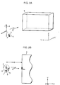
- Figs. 2A and 2B diagrammatically show an SAR measuring device of an embodiment according to the invention.
- the orthogonal probe structure 1 is constituted by two loop probes 2 and 3 having a common center and having loop surfaces orthogonal to each other. The probe structure 1 is placed at a location away by a distance t from the antenna 4.
- the antenna currents are calculated.
- Fig. 6 shows the relationship between the antenna currents I at the driving point and the distance d when a probe having a diameter of 10 mm is used.
- Symbol ⁇ represents the measured value
- the solid line represents the calculated value derived from the impedance at the driving point.
- the probe is placed 35 mm away from the driving point.
- Fig. 7 shows the relationship between the SAR (W/kg) of the phantom and the distance d.
- the symbol ⁇ represents the reflected waves having been corrected
- ⁇ represents the reflected waves not having been corrected
- the solid line represents the calculated values of the antenna currents.
- a phantom is used for making the evaluation.
- biological bodies such as human and animal bodies similarly in place of the phantom.
Landscapes
- Health & Medical Sciences (AREA)
- Physics & Mathematics (AREA)
- Life Sciences & Earth Sciences (AREA)
- General Health & Medical Sciences (AREA)
- Electromagnetism (AREA)
- Radiology & Medical Imaging (AREA)
- Animal Behavior & Ethology (AREA)
- Nuclear Medicine, Radiotherapy & Molecular Imaging (AREA)
- Public Health (AREA)
- Biomedical Technology (AREA)
- Veterinary Medicine (AREA)
- Engineering & Computer Science (AREA)
- Chemical & Material Sciences (AREA)
- Analytical Chemistry (AREA)
- Biochemistry (AREA)
- General Physics & Mathematics (AREA)
- Immunology (AREA)
- Pathology (AREA)
- Magnetic Resonance Imaging Apparatus (AREA)
- Measurement And Recording Of Electrical Phenomena And Electrical Characteristics Of The Living Body (AREA)
Abstract
Description
- The present invention relates to a device and method for measuring a Specific Absorption Rate (SAR) in human bodies exposed to electromagnetic waves from antennas of portable telephones, radio frequency equipment, etc. positioned in the vicinity of human bodies.
- One of the basic standard guidelines for protecting human bodies from electromagnetic waves is known as the Specific Absorption Rate (SAR). This represents a value of energy absorption per unit mass when a human body is exposed to electromagnetic waves, and the tolerable value is indicated in, for example, "Guidelines for Protection of Humans in Utilization of Electromagnetic Waves" proposed by "Electro-Communication Technology Study Council" of Japanese Ministry of Posts and Telecommunications.
- Conventionally, there has been a study wherein, by using a phantom (biological body model) having the permittivity and the permeability equivalent to those of biological bodies such as human bodies, the SAR has been measured from the incident magnetic fields on the phantom. This has been proposed by N. Kuster and Q. Balzano under the title "Energy Absorption Mechanism by Biological Bodies in the Near Field of Dipole Antennas Above 300 MHz" in IEEE Transaction on Vehicular Technology, Vol. 41, No. 1, 1992, pp 17-23.
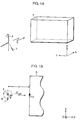
- In the conventional SAR measuring system which is adopted in the above proposal and which is illustrated in Figs. 1A and 1B attached hereto, the
electromagnetic waves 6 from half-wave dipole antenna 4 are incident perpendicularly on thephantom 5. The distance between theantenna 4 and thephantom 5 is represented by d. Where the real part of the permittivity of the phantom is represented by ε, the conductivity by σ, the mass density by ρ, and the incident magnetic field on the front surface of phantom by Hs, the SAR may be expressed by the following equation:
wherein ω represents an angular frequency, Γ represents a reflection coefficient, α represents a correction coefficient, and µo=4π×10⁻⁷. - The incident magnetic fields are proportional to the antenna currents so that the SAR can be expressed also by the antenna currents. In the half-wave dipole antenna, the SAR maximum value of the phantom is at a portion corresponding to the location of the driving point so that, where the antenna current at the driving point is assumed to be I, the incident magnetic fields may be expressed by the following equation:

The current I is calculated from the magnetic fields 8 radiating from theantenna 4 by using a magnetic fieldreceiving loop probe 7. Theprobe 7 is placed in such a way that the loop surface becomes perpendicular with respect to the X-axis at a location away by a distance t from the driving point of the probe. At this location, the radiating magnetic fields 8 have only X-direction components. - Normally, the characteristic impedance of the human body is of a lower impedance than 120π which is the characteristic impedance in air. Thus, the electromagnetic waves radiating from the antenna reflect at the front surface of the phantom. Fig. 3 shows incident waves and reflected waves when the electromagnetic fields are incident on the
phantom 5 at an incident angle of θ and the magnetic fields radiating from theantenna 4. The magnetic fields and the electric fields of the incident waves are represented by Hin and Ein, respectively, the reflected waves are represented by Hr and Er, and the radiating magnetic fields from the antenna are represented by Hi. The X-axis direction component Hr(X) and the Y-axis direction component Hr(Y) of the reflected magnetic fields at the location where the probe is placed may be expressed by the following equations, respectively:

Therefore, the magnetic fields Hp of the X-axis direction which the probe receives may be expressed by the following equation:
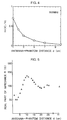
Where the phantom is located remotely, the reflected magnetic fields attenuate with distance, resulting in a small effect on the phantom. However, where the phantom is located in the vicinity of the antenna, we have appreciated that the effect from the reflected waves can no longer be ignored. - When the distance d between the antenna and the phantom is varied, the relation between the reflected magnetic fields Hr(X) in the X-direction and the radiating magnetic fields Hi will be as shown in Fig. 4. When the distance d becomes smaller than 3 cm, the reflected magnetic fields increase to more than 25%. Thus, the problem in the probe arrangement as above is that the probe receiving the magnetic fields for the calculation of the antenna currents results in being measured smaller than the actual value, which leads to a large SAR error.
- An object of the present invention, therefore, is to overcome the problems existing in the prior art and to provide a device and a method for measuring the SAR, wherein the reflected magnetic fields are corrected and the SAR is more accurately measured.
- According to a first aspect of the invention, there is provided a device for measuring a Specific Absorption Rate (SAR) in a human body exposed to electromagnetic fields radiating from an antenna, the device comprising:
a phantom having equivalent electric constant of permittivity and permeability as those of a human body; and
a probe structure having a combination of first and second loop probes orthogonal to each other, the probe structure being arranged such that the second loop probe receives only a magnetic field that has been reflected from a surface of the phantom. - According to a second aspect of the invention, there is provided a method for measuring a Specific Absorption Rate (SAR) in phantom exposed to electromagnetic fields radiating from an antenna, by using a probe structure having a combination of first and second loop probes orthogonal to each other, the method comprising the steps of:
disposing the first and second loop probes such that the second loop probe receives only a magnetic field that has been reflected from a surface of the phantom; and
distinguishing a magnetic field radiating from the antenna and the magnetic field that has been reflected from the surface of the phantom thereby correcting the magnetic field that has been reflected. - Further, in accordance with the invention, by using the probe structure constituted by two loop probes which are orthogonal to each other, the radiating magnetic field from the antenna and the reflected magnetic field from a surface of the phantom can be distinguished from each other, whereby the reflected magnetic field is corrected.
- The reflected magnetic field is corrected in the manner explained hereinafter.
- In Fig. 3, the reflected magnetic field Hr(X) may be expressed, using the incident angle θ and the Y-direction component Hr(Y), by the equations (3) and (4).

Therefore, the radiating magnetic field Hi from the antenna may be expressed by:
By measuring the Y-direction component of the reflected magnetic field at the location where the probe is placed, it is possible to correct the influence of the reflected magnetic field. - The above and other objects, features and advantages of the present invention will be apparent from the following description of preferred embodiments of the invention explained with reference to the accompanying drawings, in which:
- Figs. 1A and 1B are diagrams showing an arrangement of a conventional SAR measuring device, Fig. 1A being a perspective view thereof and Fig. 1B being a top view thereof;
- Figs. 2A and 2B are diagrams showing an arrangement of an SAR measuring device according to the present invention, Fig. 2A being a perspective view thereof and Fig. 2B being a top view thereof;
- Fig. 3 is a diagram for use in explaining the incident waves and the reflected waves when the magnetic fields are incident on the phantom at an incident angle of 8, and the magnetic fields radiating from the antenna;
- Fig. 4 is a diagram showing the relationship between the reflected magnetic field in the X-direction and the radiating magnetic field when the distance d between the antenna and the phantom is varied;
- Fig. 5 is a diagram showing the real part of the impedance at the driving point when the distance d between the antenna and the phantom is varied;
- Fig. 6 is a diagram showing antenna currents at the driving point when the distance d between the antenna and the phantom is varied; and
- Fig. 7 is a diagram showing the SAR when the distance d between the antenna and the phantom is varied.
- Now, a preferred embodiment of the invention is explained with reference to the drawings.
- Figs. 2A and 2B diagrammatically show an SAR measuring device of an embodiment according to the invention.
- In carrying out the measuring operation, waves of 900 MHz from the
antenna 4 irradiate thephantom 5. The output power of theantenna 4 is on the order of 1 W. Thephantom 5 has the real part of a relative permittivity of 41.1, a conductivity of 0.88 S/m, and a mass density of 2.4 g/cm³. The orthogonal probe structure 1 is constituted by twoloop probes antenna 4. At this location, by placing thefirst probe 2 perpendicular to the X-axis, it is possible to measure only the radiating magnetic field 8 and, by placing thesecond probe 3 perpendicular to the Y-axis, it is possible to measure only the reflected magnetic field. After the reflected magnetic field is corrected, the antenna currents are calculated. - Fig. 5 shows the real part of the impedance R (Ω) at the driving point of the antenna when the distance d is varied. As the probe gets closer to the phantom, the value of R changes and becomes a minimum at d=2 cm and reaches a maximum at d=10 cm where the distance is about 1/4 and, with the repetition of oscillations, R becomes a minimum again at d=20 cm.
- Fig. 6 shows the relationship between the antenna currents I at the driving point and the distance d when a probe having a diameter of 10 mm is used. Symbol Δ represents the measured value, the solid line represents the calculated value derived from the impedance at the driving point. The probe is placed 35 mm away from the driving point. The antenna currents become a minimum at d=10 cm and maximum at d=20 cm, with a trend wherein an increase and a decrease thereof are qualitatively opposite with respect to R. Since the measured values substantially coincide with the calculated values, it can be appreciated that the antenna currents are calculated after the reflected magnetic fields have been corrected.
- Fig. 7 shows the relationship between the SAR (W/kg) of the phantom and the distance d. In the graph, the symbol Δ represents the reflected waves having been corrected, ○ represents the reflected waves not having been corrected, and the solid line represents the calculated values of the antenna currents. Whereas, when the distance d becomes larger, the measured values (Δ and ○) become coincident with each other, when the distance d becomes smaller than 3 cm, the value without having been corrected becomes smaller and results in different characteristics. The measured values after the reflected waves have been corrected do coincide with the calculated values very well. From this, the effectiveness of a method in which the reflected waves are corrected can be appreciated.
- As described above, a phantom is used for making the evaluation. Alternatively, it is possible to evaluate biological bodies such as human and animal bodies similarly in place of the phantom.
- While the invention has been described in its preferred embodiments, it is to be understood that the words which have been used are words of description rather than limitation and that changes within the purview of the appended claims may be made without departing from the scope of the invention as defined by the claims.
Claims (6)
- A device for measuring Specific Absorption Rate (SAR) in a human body exposed to electromagnetic fields (8) radiating from an antenna (4), the device comprising:
a body (5) having substantially equivalent electric constant of permittivity and permeability as a human body, and a probe structure including a loop probe (3);
characterised in that the probe structure (1) has a combination of first and second loop probes (2,3) orthogonal to each other, the probe structure being arranged such that the second loop probe receives only a magnetic field that has been reflected from a surface of the body. - A device for measuring Specific Absorption Rate according to claim 1, in which the first loop probe is disposed perpendicular to the electromagnetic fields, and the second loop probe is disposed perpendicular to the first loop probe such that the second loop probe measures a component of the reflected magnetic field only in the direction of the first loop probe.
- A device for measuring Specific Absorption Rate according to claim 1 or 2, in which the body is a phantom.
- A method for measuring Specific Absorption Rate (SAR) in a body exposed to electromagnetic fields radiating from an antenna (4), by using a probe structure (1) having a combination of first and second loop probes (2,3) orthogonal to each other, the method comprising the steps of:
disposing the first and second loop probes such that the second loop probe receives only a magnetic field that has been reflected from a surface of the body and
distinguishing the magnetic field radiating from the antenna and the magnetic field that has been reflected from the surface of the body, and thereby correcting the magnetic field that has been reflected. - A method of measuring Specific Absorption Rate according to claim 4, in which the first loop probe is disposed perpendicular to the electromagnetic fields, and the second loop probe is disposed perpendicular to the first loop probe such that the second loop probe measures a component of the reflected magnetic field only in the direction of the first loop probe.
- A method of measuring Specific Absorption Rate according to claim 4 or 5, in which the body is a phantom.
Applications Claiming Priority (3)
| Application Number | Priority Date | Filing Date | Title |
|---|---|---|---|
| JP6226313A JP2737661B2 (en) | 1994-09-21 | 1994-09-21 | SAR measuring method and SAR measuring device |
| JP226313/94 | 1994-09-21 | ||
| JP22631394 | 1994-09-21 |
Publications (3)
| Publication Number | Publication Date |
|---|---|
| EP0702932A2 true EP0702932A2 (en) | 1996-03-27 |
| EP0702932A3 EP0702932A3 (en) | 1997-09-24 |
| EP0702932B1 EP0702932B1 (en) | 2003-04-02 |
Family
ID=16843249
Family Applications (1)
| Application Number | Title | Priority Date | Filing Date |
|---|---|---|---|
| EP95306687A Expired - Lifetime EP0702932B1 (en) | 1994-09-21 | 1995-09-21 | Method for measuring specific absorption rate of electromagnetic waves in models of human bodies |
Country Status (4)
| Country | Link |
|---|---|
| US (1) | US5610519A (en) |
| EP (1) | EP0702932B1 (en) |
| JP (1) | JP2737661B2 (en) |
| DE (1) | DE69530154T2 (en) |
Cited By (5)
| Publication number | Priority date | Publication date | Assignee | Title |
|---|---|---|---|---|
| GB2308198A (en) * | 1995-12-15 | 1997-06-18 | Nec Corp | Arrangement for evaluating a body's electrical power specific absorption rate |
| US6181136B1 (en) | 1997-10-24 | 2001-01-30 | Electronics And Telecommunications Research Institute | Method of manufacturing the human tissue phantoms for evaluation of electromagnetic wave environment |
| WO2004048949A1 (en) * | 2002-11-22 | 2004-06-10 | The Education & Research Foundation For Industry, University, And Research Institute In Chungnam National University | Sar measurement system and method of operating the same |
| CN102854400A (en) * | 2011-06-29 | 2013-01-02 | 中兴通讯股份有限公司 | Method and device for acquiring specific absorption rate of electromagnetic waves |
| CN109270361A (en) * | 2018-10-10 | 2019-01-25 | 东莞华贝电子科技有限公司 | The SAR test device and method of mobile terminal |
Families Citing this family (18)
| Publication number | Priority date | Publication date | Assignee | Title |
|---|---|---|---|---|
| US5774392A (en) * | 1996-03-28 | 1998-06-30 | Ramtron International Corporation | Bootstrapping circuit utilizing a ferroelectric capacitor |
| KR20030002957A (en) * | 2001-07-03 | 2003-01-09 | 한국전자통신연구원 | Algorithm For Evaluating Localized SAR In Human Body Exposed To Electromagnetic Fields |
| CN100422726C (en) * | 2001-08-08 | 2008-10-01 | 株式会社Ntt都科摩 | Absorbed Power Measuring Device |
| DE60300464T2 (en) * | 2002-04-22 | 2006-02-23 | Matsushita Electric Industrial Co., Ltd., Kadoma | Device for measuring the specific absorption rate based on the magnetic near field for use in a wireless device |
| US6985113B2 (en) * | 2003-04-18 | 2006-01-10 | Matsushita Electric Industrial Co., Ltd. | Radio antenna apparatus provided with controller for controlling SAR and radio communication apparatus using the same radio antenna apparatus |
| JP5554463B2 (en) * | 2004-07-05 | 2014-07-23 | 株式会社Nttドコモ | Specific absorption rate measuring device |
| JP2006132970A (en) * | 2004-11-02 | 2006-05-25 | Ntt Docomo Inc | Specific absorption rate measuring system and method |
| KR100692920B1 (en) * | 2005-11-08 | 2007-03-12 | 충남대학교산학협력단 | Electromagnetic absorption rate measuring system and method |
| US8301133B2 (en) | 2006-12-20 | 2012-10-30 | Research In Motion Limited | Method and system for conducting hearing aid compatibility testing of a mobile communication device |
| US20080261584A1 (en) * | 2007-04-23 | 2008-10-23 | Research In Motion Limited | Method and system for conducting specific absorption rate testing of a mobile communication device |
| EP1986453B1 (en) * | 2007-04-23 | 2009-07-08 | Research In Motion Limited | Method and system for conducting specific absorption rate testing of a mobile communication device |
| US9241762B2 (en) | 2010-06-03 | 2016-01-26 | Covidien Lp | Specific absorption rate measurement and energy-delivery device characterization using image analysis |
| US8188435B2 (en) | 2010-06-03 | 2012-05-29 | Tyco Healthcare Group Lp | Specific absorption rate measurement and energy-delivery device characterization using thermal phantom and image analysis |
| US9377367B2 (en) | 2010-06-03 | 2016-06-28 | Covidien Lp | Specific absorption rate measurement and energy-delivery device characterization using thermal phantom and image analysis |
| US9468492B2 (en) | 2010-06-03 | 2016-10-18 | Covidien Lp | Specific absorption rate measurement and energy-delivery device characterization using image analysis |
| TWI414797B (en) * | 2010-07-09 | 2013-11-11 | Hon Hai Prec Ind Co Ltd | Electromagnetic wave detecting device |
| RU2648290C1 (en) * | 2016-11-29 | 2018-03-23 | Евгений Михайлович Онищенко | Device for measuring specific absorbed power of microwave electromagnetic emission |
| CN115021839B (en) * | 2022-05-26 | 2023-06-16 | 中国计量科学研究院 | SAR value correction method for wireless equipment based on 5G signals |
Family Cites Families (15)
| Publication number | Priority date | Publication date | Assignee | Title |
|---|---|---|---|---|
| US3644825A (en) * | 1969-12-31 | 1972-02-22 | Texas Instruments Inc | Magnetic detection system for detecting movement of an object utilizing signals derived from two orthogonal pickup coils |
| US3778703A (en) * | 1971-12-20 | 1973-12-11 | Sperry Rand Corp | Apparatus for detecting unlevelness of a pendulously supported flux valve by subjecting the valve to a vertical magnetic field |
| GB1552617A (en) * | 1977-02-02 | 1979-09-19 | Narda Microwave Corp | Magnetic field radiation detector |
| US4368472A (en) * | 1980-10-08 | 1983-01-11 | Dosimeter Corporation Of America | Microwave dosimeter |
| US4588993A (en) * | 1980-11-26 | 1986-05-13 | The United States Of America As Represented By The Secretary Of The Department Of Health And Human Services | Broadband isotropic probe system for simultaneous measurement of complex E- and H-fields |
| JPS5813867A (en) * | 1981-07-17 | 1983-01-26 | 旭化成株式会社 | Constructing of building |
| US4659984A (en) * | 1984-12-06 | 1987-04-21 | Doss James D | Passive integrating electromagnetic field dosimeter |
| JPS61170679A (en) * | 1985-01-24 | 1986-08-01 | Koden Electronics Co Ltd | Direction finding antenna |
| US4672309A (en) * | 1985-05-20 | 1987-06-09 | Dosimeter Corporation Of America | RF personnel dosimeter and dosimetry method for use therewith |
| US4913153A (en) * | 1987-11-13 | 1990-04-03 | Florida International University | Personal dosimeter |
| WO1989004632A1 (en) * | 1987-11-13 | 1989-06-01 | Florida International University | High frequency ammeter and personal dosimeter |
| JPH02121633A (en) * | 1988-10-31 | 1990-05-09 | Hitachi Medical Corp | Phantom for magnetic resonance tomographic equipment and preparation thereof |
| JP2544613Y2 (en) * | 1991-02-22 | 1997-08-20 | ジーイー横河メディカルシステム株式会社 | SAR monitoring device in MR device |
| JPH0523319A (en) * | 1991-07-19 | 1993-02-02 | Shimadzu Corp | Nuclear magnetic resonance diagnostic device |
| JP3174365B2 (en) * | 1991-10-09 | 2001-06-11 | 株式会社日立製作所 | Analysis support method for near-body antenna and antenna design support apparatus by the method |
-
1994
- 1994-09-21 JP JP6226313A patent/JP2737661B2/en not_active Expired - Fee Related
-
1995
- 1995-09-19 US US08/530,027 patent/US5610519A/en not_active Expired - Lifetime
- 1995-09-21 DE DE69530154T patent/DE69530154T2/en not_active Expired - Fee Related
- 1995-09-21 EP EP95306687A patent/EP0702932B1/en not_active Expired - Lifetime
Non-Patent Citations (1)
| Title |
|---|
| N. KUSTER AND Q. BALZANO: "Energy Absorption Mechanism by Biological Bodies in the Near Field of Dipole Antennas Above 300 MHz", IEEE TRANSACTION ON VEHICULAR TECHNOLOGY, vol. 41, no. 1, 1992, pages 17 - 23, XP000297037, DOI: doi:10.1109/25.120141 |
Cited By (8)
| Publication number | Priority date | Publication date | Assignee | Title |
|---|---|---|---|---|
| GB2308198A (en) * | 1995-12-15 | 1997-06-18 | Nec Corp | Arrangement for evaluating a body's electrical power specific absorption rate |
| US5789929A (en) * | 1995-12-15 | 1998-08-04 | Nec Corporation | Method and device for measuring the specific absorption rate of electric power in a simulated human body |
| GB2308198B (en) * | 1995-12-15 | 2000-11-01 | Nec Corp | Method and device for measuring the specific absorbtion rate of electric power |
| US6181136B1 (en) | 1997-10-24 | 2001-01-30 | Electronics And Telecommunications Research Institute | Method of manufacturing the human tissue phantoms for evaluation of electromagnetic wave environment |
| WO2004048949A1 (en) * | 2002-11-22 | 2004-06-10 | The Education & Research Foundation For Industry, University, And Research Institute In Chungnam National University | Sar measurement system and method of operating the same |
| CN102854400A (en) * | 2011-06-29 | 2013-01-02 | 中兴通讯股份有限公司 | Method and device for acquiring specific absorption rate of electromagnetic waves |
| CN109270361A (en) * | 2018-10-10 | 2019-01-25 | 东莞华贝电子科技有限公司 | The SAR test device and method of mobile terminal |
| CN109270361B (en) * | 2018-10-10 | 2024-04-26 | 东莞华贝电子科技有限公司 | SAR testing device and method for mobile terminal |
Also Published As
| Publication number | Publication date |
|---|---|
| DE69530154D1 (en) | 2003-05-08 |
| JP2737661B2 (en) | 1998-04-08 |
| EP0702932B1 (en) | 2003-04-02 |
| US5610519A (en) | 1997-03-11 |
| DE69530154T2 (en) | 2004-01-29 |
| JPH0894544A (en) | 1996-04-12 |
| EP0702932A3 (en) | 1997-09-24 |
Similar Documents
| Publication | Publication Date | Title |
|---|---|---|
| US5610519A (en) | Device and method for measuring specific absorption rate of electromagnetic waves in models of human bodies | |
| EP1452880B1 (en) | Apparatus for measuring specific absorption rate of radio communication apparatus | |
| JP2790103B2 (en) | Specific absorption rate measuring device and specific absorption rate measuring method | |
| EP1326070B1 (en) | Absorption power measuring device | |
| US20040017115A1 (en) | Apparatus for measuring specific absorption rate based on near magnetic field for use in radio apparatus | |
| US20020062203A1 (en) | Object tracking using a single sensor or a pair of sensors | |
| JP5106851B2 (en) | A device for checking the specific absorbance of mass produced radioactive materials | |
| JP3147100B2 (en) | SAR measurement sensor and SAR measurement device | |
| US6249248B1 (en) | Radio wave visualizing method and apparatus | |
| Kuster et al. | Experimental and numerical dosimetry | |
| Gradoni et al. | Numerical and experimental analysis of the field to enclosure coupling in reverberation chamber and comparison with anechoic chamber | |
| McCoy et al. | Field strengths and specific absorption rates in automotive environments | |
| JPH0658970A (en) | Both side jamming measuring apparatus | |
| US8135549B2 (en) | Method and device for specific absorption rate measurement of an electric field | |
| Potharazu et al. | Analysis and design of a leaky-wave EMC dipole array | |
| EP1070966A1 (en) | A method and device for determining the electrical field strength acting on an anatomical model | |
| Taki et al. | Characteristics, dosimetry & measurement of EMF | |
| Thottappillil et al. | Estimation of fields radiated by a PCB from close magnetic field measurements | |
| Meier et al. | Automated Dosimetric Scanning System for Mobile Communications | |
| JPH0658969A (en) | Three-dimensional interference measuring device | |
| JP2007163236A (en) | Electromagnetic wave measuring method and electromagnetic wave measuring device | |
| JPH11174101A (en) | Apparatus and method for measuring uniformity of electromagnetic field | |
| Swanson | Investigation of the calibration procedure from CISPR 25, Annex B, for use with vehicle component testing | |
| Hirayama et al. | Estimation of near-E field and far-field radiation pattern with only near-H field measurement by using the Yee scheme | |
| Douglas et al. | Electromagnetic Exposure from Wireless Devices as Function of Distance |
Legal Events
| Date | Code | Title | Description |
|---|---|---|---|
| PUAI | Public reference made under article 153(3) epc to a published international application that has entered the european phase |
Free format text: ORIGINAL CODE: 0009012 |
|
| AK | Designated contracting states |
Kind code of ref document: A2 Designated state(s): DE FR GB |
|
| PUAL | Search report despatched |
Free format text: ORIGINAL CODE: 0009013 |
|
| AK | Designated contracting states |
Kind code of ref document: A3 Designated state(s): DE FR GB |
|
| 17P | Request for examination filed |
Effective date: 19970827 |
|
| 17Q | First examination report despatched |
Effective date: 20011030 |
|
| GRAH | Despatch of communication of intention to grant a patent |
Free format text: ORIGINAL CODE: EPIDOS IGRA |
|
| RTI1 | Title (correction) |
Free format text: METHOD FOR MEASURING SPECIFIC ABSORPTION RATE OF ELECTROMAGNETIC WAVES IN MODELS OF HUMAN BODIES |
|
| GRAH | Despatch of communication of intention to grant a patent |
Free format text: ORIGINAL CODE: EPIDOS IGRA |
|
| GRAA | (expected) grant |
Free format text: ORIGINAL CODE: 0009210 |
|
| RAP1 | Party data changed (applicant data changed or rights of an application transferred) |
Owner name: NEC CORPORATION |
|
| AK | Designated contracting states |
Designated state(s): DE FR GB |
|
| REG | Reference to a national code |
Ref country code: GB Ref legal event code: FG4D |
|
| REF | Corresponds to: |
Ref document number: 69530154 Country of ref document: DE Date of ref document: 20030508 Kind code of ref document: P |
|
| ET | Fr: translation filed | ||
| PLBE | No opposition filed within time limit |
Free format text: ORIGINAL CODE: 0009261 |
|
| STAA | Information on the status of an ep patent application or granted ep patent |
Free format text: STATUS: NO OPPOSITION FILED WITHIN TIME LIMIT |
|
| 26N | No opposition filed |
Effective date: 20040105 |
|
| PGFP | Annual fee paid to national office [announced via postgrant information from national office to epo] |
Ref country code: FR Payment date: 20050823 Year of fee payment: 11 |
|
| PGFP | Annual fee paid to national office [announced via postgrant information from national office to epo] |
Ref country code: DE Payment date: 20050915 Year of fee payment: 11 |
|
| PGFP | Annual fee paid to national office [announced via postgrant information from national office to epo] |
Ref country code: GB Payment date: 20050921 Year of fee payment: 11 |
|
| PG25 | Lapsed in a contracting state [announced via postgrant information from national office to epo] |
Ref country code: DE Free format text: LAPSE BECAUSE OF NON-PAYMENT OF DUE FEES Effective date: 20070403 |
|
| GBPC | Gb: european patent ceased through non-payment of renewal fee |
Effective date: 20060921 |
|
| REG | Reference to a national code |
Ref country code: FR Ref legal event code: ST Effective date: 20070531 |
|
| PG25 | Lapsed in a contracting state [announced via postgrant information from national office to epo] |
Ref country code: GB Free format text: LAPSE BECAUSE OF NON-PAYMENT OF DUE FEES Effective date: 20060921 |
|
| PG25 | Lapsed in a contracting state [announced via postgrant information from national office to epo] |
Ref country code: FR Free format text: LAPSE BECAUSE OF NON-PAYMENT OF DUE FEES Effective date: 20061002 |