EP0702965A1 - Dispositif d'aspiration et d'irrigation avec trois tuyaux - Google Patents
Dispositif d'aspiration et d'irrigation avec trois tuyaux Download PDFInfo
- Publication number
- EP0702965A1 EP0702965A1 EP95114879A EP95114879A EP0702965A1 EP 0702965 A1 EP0702965 A1 EP 0702965A1 EP 95114879 A EP95114879 A EP 95114879A EP 95114879 A EP95114879 A EP 95114879A EP 0702965 A1 EP0702965 A1 EP 0702965A1
- Authority
- EP
- European Patent Office
- Prior art keywords
- suction
- irrigation device
- channels
- parts
- normally
- Prior art date
- Legal status (The legal status is an assumption and is not a legal conclusion. Google has not performed a legal analysis and makes no representation as to the accuracy of the status listed.)
- Withdrawn
Links
Images


Classifications
-
- A—HUMAN NECESSITIES
- A61—MEDICAL OR VETERINARY SCIENCE; HYGIENE
- A61M—DEVICES FOR INTRODUCING MEDIA INTO, OR ONTO, THE BODY; DEVICES FOR TRANSDUCING BODY MEDIA OR FOR TAKING MEDIA FROM THE BODY; DEVICES FOR PRODUCING OR ENDING SLEEP OR STUPOR
- A61M1/00—Suction or pumping devices for medical purposes; Devices for carrying-off, for treatment of, or for carrying-over, body-liquids; Drainage systems
- A61M1/71—Suction drainage systems
- A61M1/74—Suction control
- A61M1/743—Suction control by changing the cross-section of the line, e.g. flow regulating valves
-
- A—HUMAN NECESSITIES
- A61—MEDICAL OR VETERINARY SCIENCE; HYGIENE
- A61M—DEVICES FOR INTRODUCING MEDIA INTO, OR ONTO, THE BODY; DEVICES FOR TRANSDUCING BODY MEDIA OR FOR TAKING MEDIA FROM THE BODY; DEVICES FOR PRODUCING OR ENDING SLEEP OR STUPOR
- A61M1/00—Suction or pumping devices for medical purposes; Devices for carrying-off, for treatment of, or for carrying-over, body-liquids; Drainage systems
- A61M1/71—Suction drainage systems
- A61M1/72—Cassettes forming partially or totally the fluid circuit
-
- A—HUMAN NECESSITIES
- A61—MEDICAL OR VETERINARY SCIENCE; HYGIENE
- A61M—DEVICES FOR INTRODUCING MEDIA INTO, OR ONTO, THE BODY; DEVICES FOR TRANSDUCING BODY MEDIA OR FOR TAKING MEDIA FROM THE BODY; DEVICES FOR PRODUCING OR ENDING SLEEP OR STUPOR
- A61M1/00—Suction or pumping devices for medical purposes; Devices for carrying-off, for treatment of, or for carrying-over, body-liquids; Drainage systems
- A61M1/71—Suction drainage systems
- A61M1/77—Suction-irrigation systems
- A61M1/774—Handpieces specially adapted for providing suction as well as irrigation, either simultaneously or independently
-
- A—HUMAN NECESSITIES
- A61—MEDICAL OR VETERINARY SCIENCE; HYGIENE
- A61M—DEVICES FOR INTRODUCING MEDIA INTO, OR ONTO, THE BODY; DEVICES FOR TRANSDUCING BODY MEDIA OR FOR TAKING MEDIA FROM THE BODY; DEVICES FOR PRODUCING OR ENDING SLEEP OR STUPOR
- A61M3/00—Medical syringes, e.g. enemata; Irrigators
- A61M3/02—Enemata; Irrigators
- A61M3/0201—Cassettes therefor
-
- A—HUMAN NECESSITIES
- A61—MEDICAL OR VETERINARY SCIENCE; HYGIENE
- A61M—DEVICES FOR INTRODUCING MEDIA INTO, OR ONTO, THE BODY; DEVICES FOR TRANSDUCING BODY MEDIA OR FOR TAKING MEDIA FROM THE BODY; DEVICES FOR PRODUCING OR ENDING SLEEP OR STUPOR
- A61M2205/00—General characteristics of the apparatus
- A61M2205/12—General characteristics of the apparatus with interchangeable cassettes forming partially or totally the fluid circuit
Definitions
- This invention relates to suction-irrigation devices and more particularly to such devices that are specially adapted for use in performing medical procedures.
- Multi-element suction-irrigation devices have heretofore been proposed, illustrative of which are those described in United States Patents 790,353 granted to E. S. Estlingen on May 23, 1905; 2,624,364 granted to G. C. Detlefsen on January 6, 1953; 4,425,113 granted to Arnold C. Bilstad on January 10, 1984; 4,425,116 granted to Arnold C. Bilstad et al. on January 10, 1984; 4,852,551 granted to Erie A. Opie et al. on August 1, 1989; and 5,195,959 granted to Paul C. Smith on March 23, 1993.
- these patents disclose various forms of squeeze control, multi-passage conduits, disposable inserts, trumpet-type control valves and hinged housings.
- the improved suction-irrigation device includes a hinged housing for ease of opening, a contoured interior adapted for receiving a disposable tri-tubular cassette that is discarded after each use, a plurality of improved trumpet type piston-operated plungers in combination with rollers and wedging surfaces to facilitate squeeze control of flow through the cassette tubes, and push/snap on-off cassette connections for connecting tubing to facilitate rapid deployment and re-deployment of the suction-irrigation device.
- a hinged housing for ease of opening
- a contoured interior adapted for receiving a disposable tri-tubular cassette that is discarded after each use
- a plurality of improved trumpet type piston-operated plungers in combination with rollers and wedging surfaces to facilitate squeeze control of flow through the cassette tubes
- push/snap on-off cassette connections for connecting tubing to facilitate rapid deployment and re-deployment of the suction-irrigation device.
- a generally symmetrical housing is employed, and in-line trumpet valves are disposed along the longitudinal axis of the housing, thus rendering the unit equally usable in either the right or left hand.
- the principal parts of the housing are hinged for ease of opening while including interior surfaces that are contoured to form-fit with the exterior surfaces of the disposable tri-tubular cassette that fits therewithin, thus facilitating assembly use and re-use.
- the aforementioned trumpet valve elements are each spring loaded and fitted with a roller and an engaging inclined plane or wedge which moves a connected member into and out of engagement with a predetermined portion of a corresponding one of the tri-tubular cassette tubes, thus facilitating control and adding to user feel associated with flow control.
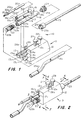
- FIG. 1 it will be seen to be a perspective view of the inventive suction-irrigation device 10, partially exploded to facilitate description thereof. It is seen to include an exterior housing 11 having a principal housing portion 12 and an attached hinged closure member 13.
- the proximal end 14 includes three semi-circular spaces 14a, 14b and 14c which, when closure member 13 is swung upwardly about its hinge 15, mate with corresponding semi-circular spaces 13a, 13b and 13c to form circular openings tightly enclosing proximal portions 16a, 17a and 18a of tubes 16, 17 and 18 of tri-tubular disposable insert 19.
- tubes 16 and 17 of disposable insert 19 are resilient and may be made of any of a variety of well-suited surgical materials such as silicone rubber surgical tubing.
- a mating tubular member 20 which is fitted at its proximal end 20a with a quick connect/disconnect collar 20b to which irrigating fluid line 21 is connected in the conventional manner.
- a conventional check valve may be interposed in the line 21, collar connector 20b or tubular member 20.
- the tri-tubular disposable insert 19 is comprised of the three tubes 16, 17 and 18 which are internally connected together near the distal end 18b of tube 18 ( Figure 3) so as to provide for commonality of fluid flow therewithin.
- Tube 18 is preferably made of rigid or semi-rigid material as may be portions of tubes 16 and 17. However, at least in regions of tubes 16 and 17 as depicted by rectangles 16b and 17b, tubes 16 and 17 will either be flexible or will include a flexible portion that is adapted for being pinched so as to close the passageways through tubes 16 and 17.
- tube 18 preferably is made of rigid or semi-rigid material is so as to facilitate the provision of threads in both its proximal and distal ends.
- female threads 18c are provided to mate with closure plug 22 which is fitted at its forward end with male engaging threads 22a.
- Closure plug 22 is provided at its proximal end with a closure member 22b that serves to seal the proximal end when in place but which may be removed so as to open up a passage therethrough. Accordingly, provision is made for either sealing the proximal end 18a of tube 18 or opening it so that a surgical instrument may be inserted therein to pass through tube 18 and surgical member 23 to a patient's interior, thus facilitating performance of certain surgical procedures.
- Adapter collar 24 is conventional and preferably includes a quick connect/disconnect feature as represented by the semi-circular projection 23a on proximal end 23b.
- suction coupling tube 25 that is adapted for insertion into and frictional engagement with tube 17.
- Suction coupling tube 25 is provided as an interface between tube 17 of tri-tubular disposable insert 19 and a conventional source of suction (not shown). Since, as will be recognized by those skilled in the art, problems associated with potential contamination are particularly acute in suction lines, it is contemplated that a sterile fluid trap will be interconnected in the suction line leading from tube 25 to the conventional suction source. Although such fluid trap may be used repeatedly provided adequate sterilization procedures are followed, it is contemplated that relatively inexpensive fluid traps will be used with the suction-irrigation device described herein, thus reducing time and effort in making ready for the next patient. It will also be evident that although tube 25 is shown as fitted with a collar 25a, such is optional and may readily be omitted if desired.
- hinged closure member 13 is fitted with a conventional flexible tang 26 that is fitted with a projection 26a adapted for projecting into opening 12a and thus locking closure member 13 to principal portion 12 when member 13 is swung upwardly about its hinge 15 into a closed position.
- a sideways deflection of tang 25 under manual pressure will disengage it from opening 12a, thus freeing member 13 to be swung downwardly to the position shown in Figure 1.
- buttons 27 and 28 are seen a pair of in-line trumpet valve actuating buttons 27 and 28. As depicted, button 27 is proximal and controls suction, whereas button 28 is distal and controls irrigation. Operation of these buttons and the corresponding opening and closing of passageways through tubes 16 and 17 will be evident from the description below.
- FIG 2 it will be seen to depict the suction-irrigation device 10 of Figure 1 in its assembled and locked condition.
- tang projection 26a is residing within recess 12a.
- Collars 16c and 17c are shown in place to aid in correctly positioning the tri-tubular disposable insert 19 in its correct position within the housing 11.
- Removable closure member 22b is shown in place; and to identify the sections of Figures 5, 6 and 7, pairs of conventional section lines are included.
- Figure 3 depicts the tri-tubular disposable insert 19 in detail.
- collars 16c and 17c and the internal female threads 18d provided in the distal end 18b of tubular portion 18.
- the confluence of tubes 16, 17 and 18 is also shown as at points 16d and 17d where the inner passageways are joined together to provide fluid communication therebetween.
- press fittings or other known types of threadless connectors could be substituted for the threaded connections.
- Figure 4 is a sectional view taken along the section lines 4-4 which, it will be observed, pass through regions 16b and 17b. It will be recalled that regions 16b and 17b represent resilient regions of tubes 16 and 17, resilient regions provided so that they are readily deformable to the extent that flow therethrough may be readily and entirely pinched off by the actuating mechanism described in connection with Figures 5-11.
- tubes 16 and 17 may be made mostly or entirely of resilient material through which flow can be pinched off entirely after which the material will return to its original condition when pinching effort is removed, material such as surgical tubing; or the principal portions of tubes 16 and 17 may be of non-resilient material and only a part such as that exposed at regions 16b and 17b be fully pinchable. Regardless of which of these alternatives is employed, it is important that a portion of tubes 16 and 17 be capable of being pinched off so as to control flow of liquids or gaseous fluids therethrough.
- distal portions of members 20 and 25 are made of resilient material and are exposed through regions 16b and 17b which are formed in the walls of tubes 16 and 17 respectively, thereby permitting pinching forces to be applied thereto through such exposed regions.
- the sectional view of Figure 4 depicts a portion of tube 20 exposed through opening 16b, and a portion of tube 25 exposed through opening 17b. As is hereinafter described, provision is made to separately and individually apply lateral forces to these exposed regions through apertures 16b and 17b so separately control pinching and consequential fluid flow through tubes 16/20 and 17/25.
- FIG. 5 a section taken through the suction-irrigation device along section lines 5-5 of Figure 2 will be seen.
- actuating buttons 27 and 28 which are adjoined to lower camming portions 27b and 28b respectively.
- actuating buttons 27 and 28, together with their extensions 27a/b and 28a/b may be of one piece metal or molded plastic, or they may be separate pieces that are fastened together into a relatively rigid assembly. Such are shown in detail in Figures 8 and 9 respectively where their preferred geometries and camming surfaces are more readily observable.
- camming surfaces 27c/28c are seen to extend upwardly at about a 45 degree angle with respect to essentially horizontal surfaces 27d/28d thus causing cylindrical follower pins 29 and 30 to move at right angles thereto as trumpet valve mechanisms 27 and 28 ride up and down in tracks 27f/28f under finger pressure imparted by the suction-irrigation device user.
- apertures 27e and 28e parts of which are just visible in Figures 8 and 9 but which are more readily observed in Figure 5. These apertures are provided so that the camming followers 31 and 32 may respectively extend therethrough and impart pinching forces to the portions of tubes 20 and 25 that are exposed through apertures 16b and 17b as described above.
- biasing springs 33 and 34 which are provided to normally impart pinching pressure to the resilient tubes 20 and 25 through cam followers 31 and 32.
- extending portions 33a and 34a of biasing springs 33 and 34 extend through apertures in cam followers 31 and 32 so as to normally urge them inwardly to pinch off the adjacent tubes 20 and 25.
- FIG. 6 shows the interior surfaces of closure member 13 (e.g., 13a, 13b and 13c) illustrating the interior surfaces that conform to corresponding exterior surfaces of tubes 16, 17 and 18.
- Figure 7 shows those interior surfaces of principal housing portion 12 that correspondingly conform to exterior surfaces of tubes 16, 17 and 18 and including regions 27e and 28e as described above.
- Figures 10 and 11 are depict sections taken through the drawing of Figure 5 along section lines 10-10 and 11-11 respectively. They show details of the trumpet valve actuating assemblies including valve actuating buttons 27 and 28 respectively.
- actuating button 27 shown in its extended (valve closed) position in solid lines and in its depressed (valve open) position in phantom. It includes an upper enlarged portion 27g attached to extending shaft portion 27h, the interior portion of which is designated 27a.
- button 27 When button 27 is in its normal (extended) position as shown in solid lines, the aforementioned lateral thrust imparted by biasing spring 33 forces cam follower 31 into its valve closed position, thus deforming tubular section 17b as shown to pinch it off.
- member 27 moves downwardly with the result that cam follower pin 29 rides on camming surface 27c thus forcing it outwardly (because of the inclination of surface 27c), thus moving cam follower horizontally into the position shown in phantom and releasing pinching pressure on tubular section 17b, thus permitting the resiliency of the tube to cause it to resume its normal, or open, condition.
- cam follower pin 29 rides on camming surface 27c thus forcing it outwardly (because of the inclination of surface 27c), thus moving cam follower horizontally into the position shown in phantom and releasing pinching pressure on tubular section 17b, thus permitting the resiliency of the tube to cause it to resume its normal, or open, condition.
- valve assembly of Figure 11 Operation of the valve assembly of Figure 11 is generally similar to that of Figure 10 except that in Figure 11 opening and closing of tubular section 16b.
- actuating button 28 shown in its extended (valve closed) position in solid lines and in its depressed (valve open) position in phantom. It includes an upper enlarged portion 28g attached to extending shaft portion 28h, the interior portion of which is designated 28a.
- button 28 When button 28 is in its normal (extended) position as shown in solid lines, the aforementioned lateral thrust imparted by biasing spring 34 forces cam follower 32 into its valve closed position, thus deforming tubular section 16b as shown to pinch it off.
- cam follower 32 in Figure 11 generally corresponds to follower 31 in figure 10 and operates in a similar manner as cam follower pin 30 rides on camming surface 28c.
- one of the features of the invention lies in the ease with which it can be made ready for repeated use. Connecting implements and hoses are disconnected, the housing is opened, and the disposable insert is discarded and a fresh one installed, thus avoiding the time-consuming and expensive steps of sterilizing the entire suction-irrigation device.
- an additional tubular channel could be included together with an additional control trumpet valve.
- one part of the housing may be formed integrally with the disposable tri-tubular cassette and disconnectably attached to the remaining parts of the housing by any of a plurality of quick-disconnect attachments well known in the art.
Landscapes
- Health & Medical Sciences (AREA)
- Heart & Thoracic Surgery (AREA)
- Life Sciences & Earth Sciences (AREA)
- Biomedical Technology (AREA)
- Anesthesiology (AREA)
- Hematology (AREA)
- Engineering & Computer Science (AREA)
- Animal Behavior & Ethology (AREA)
- General Health & Medical Sciences (AREA)
- Public Health (AREA)
- Veterinary Medicine (AREA)
- Vascular Medicine (AREA)
- Pulmonology (AREA)
- External Artificial Organs (AREA)
Applications Claiming Priority (2)
| Application Number | Priority Date | Filing Date | Title |
|---|---|---|---|
| US08/312,479 US5496270A (en) | 1994-09-26 | 1994-09-26 | Tri-tubular suction irrigation device |
| US312479 | 1994-09-26 |
Publications (1)
| Publication Number | Publication Date |
|---|---|
| EP0702965A1 true EP0702965A1 (fr) | 1996-03-27 |
Family
ID=23211660
Family Applications (1)
| Application Number | Title | Priority Date | Filing Date |
|---|---|---|---|
| EP95114879A Withdrawn EP0702965A1 (fr) | 1994-09-26 | 1995-09-21 | Dispositif d'aspiration et d'irrigation avec trois tuyaux |
Country Status (3)
| Country | Link |
|---|---|
| US (1) | US5496270A (fr) |
| EP (1) | EP0702965A1 (fr) |
| JP (1) | JP2967041B2 (fr) |
Families Citing this family (22)
| Publication number | Priority date | Publication date | Assignee | Title |
|---|---|---|---|---|
| US5616120A (en) * | 1995-02-06 | 1997-04-01 | Andrew; Mark S. | Method and apparatus for lenticular liquefaction and aspiration |
| US5707351A (en) * | 1995-06-06 | 1998-01-13 | C.R. Bard, Inc. | Remote tubing assembly |
| US5807338A (en) * | 1995-10-20 | 1998-09-15 | United States Surgical Corporation | Modular trocar system and methods of assembly |
| US5925013A (en) * | 1997-03-26 | 1999-07-20 | Exline; Donald D. | Irrigation and evacuation cannula |
| US7033336B2 (en) * | 2002-03-29 | 2006-04-25 | Gore Enterprise Holdings, Inc. | Proximal catheter assembly having a relief valve |
| US6960189B2 (en) * | 2002-03-29 | 2005-11-01 | Gore Enterprise Holdings | Proximal catheter assembly allowing for natural and suction-assisted aspiration |
| WO2003082377A1 (fr) * | 2002-03-29 | 2003-10-09 | Arteria Medical Science, Inc. | Valve d'aspiration pour catheter |
| US20040115477A1 (en) * | 2002-12-12 | 2004-06-17 | Bruce Nesbitt | Coating reinforcing underlayment and method of manufacturing same |
| US20050107757A1 (en) * | 2003-11-14 | 2005-05-19 | Ipas | Medical vacuum aspiration device |
| US7147634B2 (en) * | 2005-05-12 | 2006-12-12 | Orion Industries, Ltd. | Electrosurgical electrode and method of manufacturing same |
| US8814861B2 (en) * | 2005-05-12 | 2014-08-26 | Innovatech, Llc | Electrosurgical electrode and method of manufacturing same |
| US10271716B2 (en) | 2008-06-27 | 2019-04-30 | C.R. Bard, Inc. | Endoscopic vacuum controller |
| USD621928S1 (en) * | 2008-10-17 | 2010-08-17 | Karl Storz Gmbh & Co. Kg | Channel separator |
| US8840596B2 (en) * | 2009-09-17 | 2014-09-23 | Arthrex, Inc. | Removable suction assembly for medical handpieces |
| US8840595B2 (en) * | 2009-09-17 | 2014-09-23 | Arthrex, Inc. | Removable suction assembly for medical handpieces |
| WO2011100703A1 (fr) * | 2010-02-12 | 2011-08-18 | Aspen Motion Technologies Inc. D/B/A | Soupape à vide et procédé associé |
| US9037600B1 (en) * | 2011-01-28 | 2015-05-19 | Yahoo! Inc. | Any-image labeling engine |
| US9218364B1 (en) | 2011-01-28 | 2015-12-22 | Yahoo! Inc. | Monitoring an any-image labeling engine |
| US9248228B2 (en) | 2013-01-18 | 2016-02-02 | Peter L. Bono | Suction and irrigation apparatus with anti-clogging capability |
| US9633272B2 (en) | 2013-02-15 | 2017-04-25 | Yahoo! Inc. | Real time object scanning using a mobile phone and cloud-based visual search engine |
| CN109847181B (zh) * | 2019-03-25 | 2024-07-23 | 日照市中医医院 | 产科清洁装置 |
| US12220139B2 (en) | 2022-03-20 | 2025-02-11 | Von Vascular, Inc. | System, devices and methods for removing obstructions in body lumens |
Citations (11)
| Publication number | Priority date | Publication date | Assignee | Title |
|---|---|---|---|---|
| US790353A (en) | 1904-08-31 | 1905-05-23 | Everett S Estlingen | Irrigator for urethral or other cavities. |
| US2624364A (en) | 1950-11-17 | 1953-01-06 | Crane Co | Diverter valve |
| US4425116A (en) | 1980-04-14 | 1984-01-10 | Baxter Travenol Laboratories, Inc. | Control system for fluid flow apparatus |
| US4425113A (en) | 1982-06-21 | 1984-01-10 | Baxter Travenol Laboratories, Inc. | Flow control mechanism for a plasmaspheresis assembly or the like |
| US4852551A (en) | 1988-04-22 | 1989-08-01 | Opielab, Inc. | Contamination-free endoscope valves for use with a disposable endoscope sheath |
| DE9115742U1 (de) * | 1991-12-19 | 1992-02-27 | Storz, Karl, Dr.med.h.c., 7200 Tuttlingen | Gerät mit einer Elektrode und einem rohrförmigen Schaft zum Einsatz in ein medizinisches Endoskop |
| WO1993003777A1 (fr) * | 1990-05-08 | 1993-03-04 | Bryan James F | Catheters et valve pour aspiration endotracheale |
| US5195959A (en) | 1991-05-31 | 1993-03-23 | Paul C. Smith | Electrosurgical device with suction and irrigation |
| EP0537573A2 (fr) * | 1991-10-18 | 1993-04-21 | United States Surgical Corporation | Instrument chirurgical endoscopique à aspiration et irrigation |
| WO1993023095A1 (fr) * | 1992-05-18 | 1993-11-25 | Yab Revo-Tech Inc. | Instrument chirurgical a fonctions multiples |
| US5295956A (en) * | 1992-10-09 | 1994-03-22 | Symbiosis Corporation | Endoscopic suction instrument having variable suction strength capabilities |
Family Cites Families (15)
| Publication number | Priority date | Publication date | Assignee | Title |
|---|---|---|---|---|
| US2643848A (en) * | 1949-09-12 | 1953-06-30 | Hoffmann Joseph | Wedge-actuated clamp for resilient tubing and the like |
| US4493695A (en) * | 1982-06-01 | 1985-01-15 | Site Microsurgical Systems, Inc. | Opthalmic microsurgical system cassette assembly |
| US4428745A (en) * | 1982-06-21 | 1984-01-31 | Baxter Travenol Laboratories, Inc. | Flow control mechanism for a plasmapheresis assembly or the like |
| US4524802A (en) * | 1984-10-01 | 1985-06-25 | Bio-Chem Valve Corp. | Pinch valve |
| US4713051A (en) * | 1985-05-21 | 1987-12-15 | Coopervision, Inc. | Cassette for surgical irrigation and aspiration and sterile package therefor |
| US4946434A (en) * | 1986-07-22 | 1990-08-07 | Haemonetics Corporation | Disposable manifold and valve |
| US4821996A (en) * | 1987-01-28 | 1989-04-18 | Baxter Travenol Laboratories, Inc. | Fluid flow control valve and transfer set |
| US5195960A (en) * | 1987-04-27 | 1993-03-23 | Site Microsurgical Systems, Inc. | Disposable vacuum/peristaltic pump cassette system |
| US5163900A (en) * | 1989-03-16 | 1992-11-17 | Surgin Surgical Instrumentation, Inc. | Disposable cassette systems |
| JPH0693916B2 (ja) * | 1990-10-31 | 1994-11-24 | テルモ株式会社 | 輸液ポンプ |
| DE4208054C2 (de) * | 1991-03-21 | 1995-04-20 | Schiwa Gmbh | Leitungs-System zum Spülen eines extrakorporalen Kreislaufs bei der Hämodialyse, Hämofiltration und Hämodiafiltration |
| US5322503A (en) * | 1991-10-18 | 1994-06-21 | Desai Ashvin H | Endoscopic surgical instrument |
| US5254083A (en) * | 1992-02-10 | 1993-10-19 | Conmed Corporation | Suction and irrigation apparatus |
| US5230704A (en) * | 1992-06-26 | 1993-07-27 | Biomedical Dynamics Corporation | Suction/irrigation instrument having reusable handle with disposable fluid path |
| US5354291A (en) * | 1992-10-09 | 1994-10-11 | Symbiosis Corporation | Probe for endoscopic suction-irrigation instruments having a proximal port for receiving an additional probe therethrough |
-
1994
- 1994-09-26 US US08/312,479 patent/US5496270A/en not_active Expired - Fee Related
-
1995
- 1995-09-21 EP EP95114879A patent/EP0702965A1/fr not_active Withdrawn
- 1995-09-26 JP JP7247785A patent/JP2967041B2/ja not_active Expired - Lifetime
Patent Citations (11)
| Publication number | Priority date | Publication date | Assignee | Title |
|---|---|---|---|---|
| US790353A (en) | 1904-08-31 | 1905-05-23 | Everett S Estlingen | Irrigator for urethral or other cavities. |
| US2624364A (en) | 1950-11-17 | 1953-01-06 | Crane Co | Diverter valve |
| US4425116A (en) | 1980-04-14 | 1984-01-10 | Baxter Travenol Laboratories, Inc. | Control system for fluid flow apparatus |
| US4425113A (en) | 1982-06-21 | 1984-01-10 | Baxter Travenol Laboratories, Inc. | Flow control mechanism for a plasmaspheresis assembly or the like |
| US4852551A (en) | 1988-04-22 | 1989-08-01 | Opielab, Inc. | Contamination-free endoscope valves for use with a disposable endoscope sheath |
| WO1993003777A1 (fr) * | 1990-05-08 | 1993-03-04 | Bryan James F | Catheters et valve pour aspiration endotracheale |
| US5195959A (en) | 1991-05-31 | 1993-03-23 | Paul C. Smith | Electrosurgical device with suction and irrigation |
| EP0537573A2 (fr) * | 1991-10-18 | 1993-04-21 | United States Surgical Corporation | Instrument chirurgical endoscopique à aspiration et irrigation |
| DE9115742U1 (de) * | 1991-12-19 | 1992-02-27 | Storz, Karl, Dr.med.h.c., 7200 Tuttlingen | Gerät mit einer Elektrode und einem rohrförmigen Schaft zum Einsatz in ein medizinisches Endoskop |
| WO1993023095A1 (fr) * | 1992-05-18 | 1993-11-25 | Yab Revo-Tech Inc. | Instrument chirurgical a fonctions multiples |
| US5295956A (en) * | 1992-10-09 | 1994-03-22 | Symbiosis Corporation | Endoscopic suction instrument having variable suction strength capabilities |
Also Published As
| Publication number | Publication date |
|---|---|
| JP2967041B2 (ja) | 1999-10-25 |
| US5496270A (en) | 1996-03-05 |
| JPH08173524A (ja) | 1996-07-09 |
Similar Documents
| Publication | Publication Date | Title |
|---|---|---|
| US5496270A (en) | Tri-tubular suction irrigation device | |
| US20220296802A1 (en) | Connector with Valve for Negative Pressure Wound Therapy System | |
| US5230704A (en) | Suction/irrigation instrument having reusable handle with disposable fluid path | |
| US7726315B2 (en) | Valves | |
| US5827218A (en) | Surgical suction pool tip | |
| US4963132A (en) | Capped fluidic connector | |
| KR102862740B1 (ko) | 폐쇄 멈춤 꼭지 | |
| US3916909A (en) | Suction surgical instrument of the forceps type | |
| EP2941291B1 (fr) | Perfectionnements apportés à des clapets | |
| CA2459992C (fr) | Dispositif regulateur d'ecoulement | |
| US20130303979A1 (en) | Suction and irrigation device | |
| US10052472B2 (en) | Coupler for endoscope fluid supply | |
| JP4728810B2 (ja) | 接続具 | |
| EP0653221B1 (fr) | Point de prise d'échantillon avec raccord sans aiguille | |
| US8443824B2 (en) | Fluid flow controller | |
| EP2777760B1 (fr) | Dispositif de soupape pour la commande d'écoulement de fluide à travers de multiples chemins convergents | |
| EP1683533B1 (fr) | Connecteur | |
| US10960111B2 (en) | Modular surgical fluid control system and related methods | |
| AU2018244986A1 (en) | Coupling device for a medical instrument | |
| US20090218535A1 (en) | Flow controllers for fluid circuits | |
| EP2292296A1 (fr) | Valve sans aiguille écouvillonnable |
Legal Events
| Date | Code | Title | Description |
|---|---|---|---|
| PUAI | Public reference made under article 153(3) epc to a published international application that has entered the european phase |
Free format text: ORIGINAL CODE: 0009012 |
|
| AK | Designated contracting states |
Kind code of ref document: A1 Designated state(s): DE GB IT |
|
| 17P | Request for examination filed |
Effective date: 19960924 |
|
| 17Q | First examination report despatched |
Effective date: 19980714 |
|
| STAA | Information on the status of an ep patent application or granted ep patent |
Free format text: STATUS: THE APPLICATION IS DEEMED TO BE WITHDRAWN |
|
| 18D | Application deemed to be withdrawn |
Effective date: 19981125 |