EP0703005A1 - Eine elektrostatische Niederschlagsvorrichtung - Google Patents
Eine elektrostatische Niederschlagsvorrichtung Download PDFInfo
- Publication number
- EP0703005A1 EP0703005A1 EP95306656A EP95306656A EP0703005A1 EP 0703005 A1 EP0703005 A1 EP 0703005A1 EP 95306656 A EP95306656 A EP 95306656A EP 95306656 A EP95306656 A EP 95306656A EP 0703005 A1 EP0703005 A1 EP 0703005A1
- Authority
- EP
- European Patent Office
- Prior art keywords
- precipitator
- duct
- ion source
- particles
- inlet
- Prior art date
- Legal status (The legal status is an assumption and is not a legal conclusion. Google has not performed a legal analysis and makes no representation as to the accuracy of the status listed.)
- Granted
Links
- 239000012717 electrostatic precipitator Substances 0.000 title claims abstract description 16
- 239000002245 particle Substances 0.000 claims abstract description 40
- 239000012716 precipitator Substances 0.000 claims abstract description 36
- 239000007788 liquid Substances 0.000 claims abstract description 30
- OKTJSMMVPCPJKN-UHFFFAOYSA-N Carbon Chemical compound [C] OKTJSMMVPCPJKN-UHFFFAOYSA-N 0.000 claims abstract description 21
- 229910052799 carbon Inorganic materials 0.000 claims abstract description 21
- 239000007789 gas Substances 0.000 claims description 32
- 238000000034 method Methods 0.000 claims description 10
- 239000004094 surface-active agent Substances 0.000 claims description 7
- 239000002195 soluble material Substances 0.000 claims description 6
- WQZGKKKJIJFFOK-GASJEMHNSA-N Glucose Natural products OC[C@H]1OC(O)[C@H](O)[C@@H](O)[C@@H]1O WQZGKKKJIJFFOK-GASJEMHNSA-N 0.000 claims description 2
- CZMRCDWAGMRECN-UGDNZRGBSA-N Sucrose Chemical compound O[C@H]1[C@H](O)[C@@H](CO)O[C@@]1(CO)O[C@@H]1[C@H](O)[C@@H](O)[C@H](O)[C@@H](CO)O1 CZMRCDWAGMRECN-UGDNZRGBSA-N 0.000 claims description 2
- 229930006000 Sucrose Natural products 0.000 claims description 2
- 239000011248 coating agent Substances 0.000 claims description 2
- 238000000576 coating method Methods 0.000 claims description 2
- 239000008103 glucose Substances 0.000 claims description 2
- 230000002209 hydrophobic effect Effects 0.000 claims description 2
- 239000011261 inert gas Substances 0.000 claims description 2
- 150000003839 salts Chemical class 0.000 claims description 2
- 239000005720 sucrose Substances 0.000 claims description 2
- 125000002791 glucosyl group Chemical group C1([C@H](O)[C@@H](O)[C@H](O)[C@H](O1)CO)* 0.000 claims 1
- 239000003595 mist Substances 0.000 abstract description 4
- 150000002500 ions Chemical class 0.000 description 14
- XLYOFNOQVPJJNP-UHFFFAOYSA-N water Substances O XLYOFNOQVPJJNP-UHFFFAOYSA-N 0.000 description 11
- XKRFYHLGVUSROY-UHFFFAOYSA-N Argon Chemical compound [Ar] XKRFYHLGVUSROY-UHFFFAOYSA-N 0.000 description 6
- FAPWRFPIFSIZLT-UHFFFAOYSA-M Sodium chloride Chemical compound [Na+].[Cl-] FAPWRFPIFSIZLT-UHFFFAOYSA-M 0.000 description 5
- PEDCQBHIVMGVHV-UHFFFAOYSA-N Glycerine Chemical compound OCC(O)CO PEDCQBHIVMGVHV-UHFFFAOYSA-N 0.000 description 4
- 239000004809 Teflon Substances 0.000 description 4
- 229920006362 Teflon® Polymers 0.000 description 4
- 229910052786 argon Inorganic materials 0.000 description 3
- 239000000126 substance Substances 0.000 description 3
- 210000003414 extremity Anatomy 0.000 description 2
- 235000011187 glycerol Nutrition 0.000 description 2
- 229910001220 stainless steel Inorganic materials 0.000 description 2
- 239000010935 stainless steel Substances 0.000 description 2
- 229910000831 Steel Inorganic materials 0.000 description 1
- NIXOWILDQLNWCW-UHFFFAOYSA-N acrylic acid group Chemical group C(C=C)(=O)O NIXOWILDQLNWCW-UHFFFAOYSA-N 0.000 description 1
- WQZGKKKJIJFFOK-VFUOTHLCSA-N beta-D-glucose Chemical compound OC[C@H]1O[C@@H](O)[C@H](O)[C@@H](O)[C@@H]1O WQZGKKKJIJFFOK-VFUOTHLCSA-N 0.000 description 1
- 230000005587 bubbling Effects 0.000 description 1
- 238000010276 construction Methods 0.000 description 1
- 239000013078 crystal Substances 0.000 description 1
- 239000008246 gaseous mixture Substances 0.000 description 1
- 238000010438 heat treatment Methods 0.000 description 1
- 239000011810 insulating material Substances 0.000 description 1
- 210000003141 lower extremity Anatomy 0.000 description 1
- 239000000203 mixture Substances 0.000 description 1
- 230000002285 radioactive effect Effects 0.000 description 1
- 239000011780 sodium chloride Substances 0.000 description 1
- 239000010959 steel Substances 0.000 description 1
- 238000005406 washing Methods 0.000 description 1
Images


Classifications
-
- B—PERFORMING OPERATIONS; TRANSPORTING
- B03—SEPARATION OF SOLID MATERIALS USING LIQUIDS OR USING PNEUMATIC TABLES OR JIGS; MAGNETIC OR ELECTROSTATIC SEPARATION OF SOLID MATERIALS FROM SOLID MATERIALS OR FLUIDS; SEPARATION BY HIGH-VOLTAGE ELECTRIC FIELDS
- B03C—MAGNETIC OR ELECTROSTATIC SEPARATION OF SOLID MATERIALS FROM SOLID MATERIALS OR FLUIDS; SEPARATION BY HIGH-VOLTAGE ELECTRIC FIELDS
- B03C3/00—Separating dispersed particles from gases or vapour, e.g. air, by electrostatic effect
- B03C3/02—Plant or installations having external electricity supply
- B03C3/16—Plant or installations having external electricity supply wet type
-
- B—PERFORMING OPERATIONS; TRANSPORTING
- B03—SEPARATION OF SOLID MATERIALS USING LIQUIDS OR USING PNEUMATIC TABLES OR JIGS; MAGNETIC OR ELECTROSTATIC SEPARATION OF SOLID MATERIALS FROM SOLID MATERIALS OR FLUIDS; SEPARATION BY HIGH-VOLTAGE ELECTRIC FIELDS
- B03C—MAGNETIC OR ELECTROSTATIC SEPARATION OF SOLID MATERIALS FROM SOLID MATERIALS OR FLUIDS; SEPARATION BY HIGH-VOLTAGE ELECTRIC FIELDS
- B03C3/00—Separating dispersed particles from gases or vapour, e.g. air, by electrostatic effect
- B03C3/34—Constructional details or accessories or operation thereof
- B03C3/40—Electrode constructions
- B03C3/45—Collecting-electrodes
- B03C3/53—Liquid, or liquid-film, electrodes
-
- B—PERFORMING OPERATIONS; TRANSPORTING
- B03—SEPARATION OF SOLID MATERIALS USING LIQUIDS OR USING PNEUMATIC TABLES OR JIGS; MAGNETIC OR ELECTROSTATIC SEPARATION OF SOLID MATERIALS FROM SOLID MATERIALS OR FLUIDS; SEPARATION BY HIGH-VOLTAGE ELECTRIC FIELDS
- B03C—MAGNETIC OR ELECTROSTATIC SEPARATION OF SOLID MATERIALS FROM SOLID MATERIALS OR FLUIDS; SEPARATION BY HIGH-VOLTAGE ELECTRIC FIELDS
- B03C3/00—Separating dispersed particles from gases or vapour, e.g. air, by electrostatic effect
- B03C3/34—Constructional details or accessories or operation thereof
- B03C3/40—Electrode constructions
- B03C3/60—Use of special materials other than liquids
-
- B—PERFORMING OPERATIONS; TRANSPORTING
- B03—SEPARATION OF SOLID MATERIALS USING LIQUIDS OR USING PNEUMATIC TABLES OR JIGS; MAGNETIC OR ELECTROSTATIC SEPARATION OF SOLID MATERIALS FROM SOLID MATERIALS OR FLUIDS; SEPARATION BY HIGH-VOLTAGE ELECTRIC FIELDS
- B03C—MAGNETIC OR ELECTROSTATIC SEPARATION OF SOLID MATERIALS FROM SOLID MATERIALS OR FLUIDS; SEPARATION BY HIGH-VOLTAGE ELECTRIC FIELDS
- B03C3/00—Separating dispersed particles from gases or vapour, e.g. air, by electrostatic effect
- B03C3/34—Constructional details or accessories or operation thereof
- B03C3/74—Cleaning the electrodes
- B03C3/78—Cleaning the electrodes by washing
-
- Y—GENERAL TAGGING OF NEW TECHNOLOGICAL DEVELOPMENTS; GENERAL TAGGING OF CROSS-SECTIONAL TECHNOLOGIES SPANNING OVER SEVERAL SECTIONS OF THE IPC; TECHNICAL SUBJECTS COVERED BY FORMER USPC CROSS-REFERENCE ART COLLECTIONS [XRACs] AND DIGESTS
- Y10—TECHNICAL SUBJECTS COVERED BY FORMER USPC
- Y10S—TECHNICAL SUBJECTS COVERED BY FORMER USPC CROSS-REFERENCE ART COLLECTIONS [XRACs] AND DIGESTS
- Y10S261/00—Gas and liquid contact apparatus
- Y10S261/48—Sonic vibrators
Definitions
- the present invention relates to electrostatic precipitators.
- Described in US Patent 5,064,634 is a method and apparatus for producing an inhalable radionuclide.
- a carbon crucible heated to a temperature within the range of 1500°C to 2500°C.
- the carbon crucible under such a temperature produces carbon particles of the size about 10nm.
- Ordinary methods of incorporating these particles into solution by bubbling are unsatisfactory.
- a further problem associated with their collection is their radioactive nature. Any collection system needs to shield against operator exposure.
- an electrostatic precipitator comprising: a housing defining a duct through which a gas containing carbon particles passes, said duct having an inlet and an outlet; an ion source past which the gas passes to charge the particles; an electrode between said inlet and said outlet and spaced downstream from said ion source; means to establish an electric potential between said ion source and said electrode; and wherein said electrode is coated with a soluble material to which the particles are attracted so as to become deposited thereon.
- an electrode for an electrostatic precipitator said electrode including a coating of a soluble material upon which the particles are deposited by being attracted thereto.
- an electrostatic precipitator to collect particles from a gas stream, said precipitator comprising: a duct through which the gas passes between an inlet and an outlet; an ion source between said inlet and said outlet and past which said gas passes to have the particles charged; a reservoir containing a liquid past which the gas passes; and means to establish an electric potential between said ion source and said reservoir so that particles are attracted to said liquid.
- an electrostatic precipitator comprising: a housing defining a duct through which a gas containing carbon particles passes, said duct having an inlet and an outlet; an ion source projecting into said duct and located between said inlet and said outlet; a wall surrounding at least part of said duct between said inlet and said outlet; means in said duct to receive a liquid; means to enable the establishment of an electric potential between said ion source and said liquid; means to cause said liquid to produce droplets to be dispersed in said duct; and wherein upon the application of said electric potential, said droplets and particles are attracted to said wall.
- a method of collecting carbon particles including the steps of: passing a gas stream containing the particles, through a chamber, the gas stream including an inert gas and air; passing the gas stream past an ion source within the chamber to charge the particles; attracting the particles to an electrode by establishing an electrical potential between said ion source and said electrode.
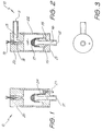
- FIG. 1 to 3 of the accompanying drawings there is schematically depicted an electrostatic precipitator 10.
- the precipitator 10 collects carbon particles from a gas stream passing through the precipitator from an inlet 11 to an outlet 12.
- the precipitator 10 would have a field strength of 7kV and would operate at a current about 10 m A.
- Gas via the inlet 11 passes along a duct 13 to a chamber 14 wherefrom the gas exits via lateral passages 15 extending to a central passage 16 terminating with the outlet 12.
- a collecting electrode 17 which is formed of a stainless steel mesh (316 type steel) coated with glucose or sucrose which also act as surfactants. Soluble salts may also be employed. In essence it should be appreciated that the electrode need only be coated with a substance which would act as a "carrier” in respect of the carbon particles and which could be removed from the electrode 17 so as to take with it the carbon particles.
- the duct 13 leads past an ion source 18 mounted by means of an adjustment screw 19.
- the precipitator 10 has a body construction consisting of a teflon base 20 and a teflon cap 21. Joining the base 20 and cap 21 is an acrylic sleeve 22.
- the adjustment screw 19 provides one terminal, while the other terminal is provided by the screw 23.
- the screw 23 is joined to the mesh electrode 17 by means of a conductive strip or wire 24.
- a Venturi 30 is provided.
- the Venturi 30 has an inlet 31 and an outlet 32.
- the passage 33 extending between the inlet 31 and outlet 32 has a restricted portion 34 to which there extends passages 35 from a manifold 36. Extending from the manifold 36 is an air inlet 37. Accordingly, via the outlet 32, a mixture of air and argon exits, containing the carbon particles.
- the outlet 32 is connected to the inlet 11 of the electrostatic precipitator 10.
- the Venturi 30 would be formed of teflon.
- the precipitator 50 has an inlet 51 extending to a chamber 52 from which there extends one or more outlets 53.
- the lower end of the chamber 52 terminates with a reservoir 54 which receives a saline solution 55 containing a trace of glycerin to act as a surfactant.
- the reservoir 54 is provided with an inlet 56 and an outlet 57 so that the saline solution 55 may be renewed or alternatively the precipitator 50 could be arranged so that there is a steady stream through the reservoir 55.
- the inlet 55 communicates with a duct 58 which extends past an ion source 59 which is mounted via an adjustment screw 60 which provides one of the terminals.
- the other terminal 61 charges the saline solution 55 so that the carbon particles delivered to the chamber 52 are attracted to the saline solution 55.
- the carbon particles would be contained in a gaseous mixture of argon and air.
- FIG 8 there is schematically depicted an electronic precipitator 80.
- the precipitator 80 includes a generally cylindrical tube 81 closed at its upper end by an end cap 82.
- the lower end of the tube 81 is mounted in a base assembly 83 including an upper part 84, and a lower part 85.
- the tube 81, and upper part 84 cooperate to define a duct 86, with the cap 82 providing a gas outlet 87, and the upper part 84 providing a gas inlet 88.
- the gas inlet 88 terminates at the duct 86 with an opening 89.
- the opening 89 and passage 90 extending therefrom, extend substantially at a "tangent" to the cylindrical (or frusto-conical) wall 91, so that gas entering the duct 86 swirls about the longitudinal axis of the tube 81.
- the cap 82 is formed of an insulating material such as teflon as is the upper part 84.
- the lower part 85 can be formed of stainless steel. Sandwiched between the upper part 84 and lower part 85 is a diaphragm 92 which may be formed of MylarTM.
- an ultrasonic transducer and gas assembly 93 Mounted in the lower part 85 is an ultrasonic transducer and gas assembly 93.
- the cap 82 is formed integral with a stem 101.
- An ion source in the form of a needle 94 extends through the cap 82 and stem 101 to exit at the lower end thereof.
- the ion source needle 94 has a lower extremity 95.
- the precipitator 80 has a hydrophobic section 97 and a hydrophilic section 98.
- the cavity 101 between the diaphragm 92 and transducer and gas assembly 93 is filled with water and a trace of a surfactant, for example glycerin.
- a surfactant for example glycerin.
- water would be delivered to the upper surface of the diaphragm 92 via a hypodermic syringe or other means. Thereafter, the ultrasonic transducer 93 would be activated to cause the diaphragm 92 to vibrate. Typically the transducer would be an ultrasonic crystal oscillating at approximately 1.7MHz.
- the water on the diaphragm 92 would be energised to form a dense stream of "mist" (small water droplets).
- the water delivered to the diaphragm 93 would want to be saline, or other ionic chemical. in order to provide the free ions necessary for the water or other ionic chemical to be conductive.
- An electric potential is applied between the extremity 95 (corona point) and the liquid delivered to the diaphragm 92. This can be done via the needle 96.
- the ultrasonic transducer in creating the above discussed mist, causes a "washing down" of the interior wall 99 of the tube 81 surrounding the section 98.
- the water also runs down the internal wall 100 of the upper part 84.
- Particles in the gas which become ionised are therefore attracted to the water droplets and walls, while the water droplets themselves become ionised and are also attracted to the walls 99 and 100.
- an electric potential is applied to the needles 94 and 96, more particularly a positive 8kv charge is applied to the needle 95, at about 100 micro amp maximum current.
- the ultrasonic transducer is controlled to ensure that the mist does not rise to an extent that it will cause a short circuit to the extremity 95.
- the hypodermic syringe having the needle 96 is inserted in the upper part 84 to make electrical contact with the liquid on the upper part of the diaphragm 92, thereby making a return ground potential and also providing a means of introducing liquid to the interior of the precipitator 80.
- the needle 96 may also be used to remove liquid containing the carbon particles.
- the liquid could be an oil based liquid.
Landscapes
- Electrostatic Separation (AREA)
- Special Spraying Apparatus (AREA)
Applications Claiming Priority (6)
| Application Number | Priority Date | Filing Date | Title |
|---|---|---|---|
| AUPM8332/94 | 1994-09-21 | ||
| AUPM833294 | 1994-09-21 | ||
| AUPM8332A AUPM833294A0 (en) | 1994-09-21 | 1994-09-21 | A precipitator |
| AUPN3332/95 | 1995-06-02 | ||
| AUPN333295 | 1995-06-02 | ||
| AUPN3332A AUPN333295A0 (en) | 1995-06-02 | 1995-06-02 | Electrostatic cyclone precipitator |
Publications (2)
| Publication Number | Publication Date |
|---|---|
| EP0703005A1 true EP0703005A1 (de) | 1996-03-27 |
| EP0703005B1 EP0703005B1 (de) | 1999-12-22 |
Family
ID=25644776
Family Applications (1)
| Application Number | Title | Priority Date | Filing Date |
|---|---|---|---|
| EP95306656A Expired - Lifetime EP0703005B1 (de) | 1994-09-21 | 1995-09-20 | Eine elektrostatische Niederschlagsvorrichtung |
Country Status (10)
| Country | Link |
|---|---|
| US (1) | US5792241A (de) |
| EP (1) | EP0703005B1 (de) |
| JP (1) | JP3614527B2 (de) |
| AT (1) | ATE187901T1 (de) |
| CA (1) | CA2158715C (de) |
| DE (1) | DE69514059T2 (de) |
| DK (1) | DK0703005T3 (de) |
| ES (1) | ES2143009T3 (de) |
| GR (1) | GR3033042T3 (de) |
| PT (1) | PT703005E (de) |
Cited By (3)
| Publication number | Priority date | Publication date | Assignee | Title |
|---|---|---|---|---|
| ES2206018A1 (es) * | 2002-04-11 | 2004-05-01 | Consejo Sup. Investig. Cientificas | Procedimiento para la eliminacion de particulas solidas suspendidas en gases mediante un precipitador electrostatico-difusivo. |
| EP2246117A4 (de) * | 2008-02-20 | 2014-01-29 | Daikin Ind Ltd | Staubabscheider |
| FR3051377A1 (fr) * | 2016-05-23 | 2017-11-24 | Commissariat Energie Atomique | Dispositif de collecte de particules presentes dans un gaz ou melange de gaz |
Families Citing this family (21)
| Publication number | Priority date | Publication date | Assignee | Title |
|---|---|---|---|---|
| JP3367038B2 (ja) * | 1997-04-21 | 2003-01-14 | 株式会社 本家松浦酒造場 | アルコール溶液のアルコール分離装置 |
| US6375721B1 (en) * | 1997-06-13 | 2002-04-23 | Hoelter Heinz | Ionization filter for purifying air |
| US6267933B1 (en) | 1997-06-19 | 2001-07-31 | Howard Thomason | Methods of preparing and using electrostatically treated fluids |
| US6974561B1 (en) | 1997-06-19 | 2005-12-13 | Howard Thomason | Methods of preparing and using electrostatically treated fluids |
| US5948141A (en) * | 1997-09-30 | 1999-09-07 | Hewlett-Packard Company | Method and apparatus for purification of a discharge gas |
| US7318856B2 (en) * | 1998-11-05 | 2008-01-15 | Sharper Image Corporation | Air treatment apparatus having an electrode extending along an axis which is substantially perpendicular to an air flow path |
| JP2000350055A (ja) | 1999-06-08 | 2000-12-15 | Nec Corp | ディジタルビデオカメラの輪郭補正装置 |
| US6585803B1 (en) * | 2000-05-11 | 2003-07-01 | University Of Southern California | Electrically enhanced electrostatic precipitator with grounded stainless steel collector electrode and method of using same |
| US6755398B1 (en) * | 2002-10-25 | 2004-06-29 | Raymond Electric (China) Ltd. | Heated water mist therapy appliance |
| US6745590B1 (en) | 2003-01-13 | 2004-06-08 | American Power Conversion | Condensate removal system |
| US20060174763A1 (en) * | 2005-02-04 | 2006-08-10 | Mainstream Engineering Corporation | Self cleaning electrostatic air cleaning system |
| AU2006243805B2 (en) * | 2005-04-29 | 2012-02-02 | The Australian National University | A method of forming an injectable radioactive composition of a carbon encapsulated radioactive particulate |
| NZ562855A (en) * | 2005-04-29 | 2010-01-29 | Univ Australian | A method of forming an injectable radioactive composition of a carbon encapsulated radioactive particulate |
| AU2006200755B2 (en) * | 2005-07-11 | 2011-02-10 | Cyclomedica Australia Pty Limited | Improved process for the production of a radioactive aerosol |
| US20070069404A1 (en) * | 2005-09-27 | 2007-03-29 | Chin-Hsia Chi | Anionic purifier |
| JP4972573B2 (ja) * | 2008-02-06 | 2012-07-11 | アサダ株式会社 | フロンの再生装置 |
| CA2721836C (en) * | 2008-04-24 | 2017-04-11 | The Australian National University | Methods for radiolabelling macromolecules |
| KR20100135312A (ko) * | 2008-04-24 | 2010-12-24 | 디 오스트레일리언 내셔널 유니버시티 | 합성 중합체의 방사성 표지화 방법 |
| FR2952552B1 (fr) * | 2009-11-19 | 2012-01-13 | Commissariat Energie Atomique | Dispositif de recuperation de nanopoudres et de poudres ultrafines contenues dans un gaz |
| US8317901B2 (en) * | 2010-02-26 | 2012-11-27 | Empire Technology Development Llc | Nanoparticle filtration |
| DK2646037T3 (en) | 2010-12-01 | 2019-03-04 | Univ Australian National | use of polyanions to inhibit the cytotoxic activity of histones in the treatment of sepsis |
Citations (8)
| Publication number | Priority date | Publication date | Assignee | Title |
|---|---|---|---|---|
| GB516158A (en) * | 1938-07-21 | 1939-12-22 | Int Precipitation Co | Method of and apparatus for electrically precipitating suspended particles from gases |
| US2597201A (en) * | 1949-11-14 | 1952-05-20 | Westinghouse Electric Corp | Adhesive liquid compositions suitable for electrostatic dust precipitators |
| CH362682A (de) * | 1958-10-04 | 1962-06-30 | Gema Ag Apparatebau Und Stanze | Elektrofilter, insbesondere zum Reinigen von Rauchgasen |
| BE717239A (de) * | 1966-04-26 | 1968-12-02 | ||
| US4388089A (en) * | 1981-06-04 | 1983-06-14 | Santek, Inc. | Self-cleaning electro-inertial precipitator unit |
| DE3600137A1 (de) * | 1986-01-07 | 1987-07-09 | Erwin Sander Elektroapparateba | Einrichtung zur hochspannungs-abgasaufbereitung |
| AT392741B (de) * | 1988-05-09 | 1991-05-27 | Farnleitner Armin | Verfahren zum abtrennen von festen oder fluessigen teilchen aus abluft |
| US5064634A (en) | 1984-10-04 | 1991-11-12 | I. J. & L. A. Tetley Manuf. Pty. Ltd. | Method of forming a radioactive metallic vapor |
Family Cites Families (4)
| Publication number | Priority date | Publication date | Assignee | Title |
|---|---|---|---|---|
| US3494099A (en) * | 1967-08-30 | 1970-02-10 | Electro Sonic Pollution Contro | Method of and apparatus for purifying polluted gases |
| US4146371A (en) * | 1977-10-25 | 1979-03-27 | Massachusetts Institute Of Technology | Electrofluidized bed agglomerator and method of agglomerating |
| DE3713651A1 (de) * | 1987-04-23 | 1988-11-17 | Thomas F Burger | Umluftwaescher |
| EP0415486B1 (de) * | 1989-08-31 | 1994-03-16 | METALLGESELLSCHAFT Aktiengesellschaft | Verfahren und Vorrichtung zur elektrostatischen Reinigung staub- und schadstoffhaltiger Abgase in mehrfeldrigen Abscheidern |
-
1995
- 1995-09-20 CA CA002158715A patent/CA2158715C/en not_active Expired - Fee Related
- 1995-09-20 ES ES95306656T patent/ES2143009T3/es not_active Expired - Lifetime
- 1995-09-20 US US08/530,983 patent/US5792241A/en not_active Expired - Lifetime
- 1995-09-20 DK DK95306656T patent/DK0703005T3/da active
- 1995-09-20 PT PT95306656T patent/PT703005E/pt unknown
- 1995-09-20 EP EP95306656A patent/EP0703005B1/de not_active Expired - Lifetime
- 1995-09-20 DE DE69514059T patent/DE69514059T2/de not_active Expired - Lifetime
- 1995-09-20 AT AT95306656T patent/ATE187901T1/de active
- 1995-09-21 JP JP24346795A patent/JP3614527B2/ja not_active Expired - Fee Related
-
2000
- 2000-03-22 GR GR20000400728T patent/GR3033042T3/el unknown
Patent Citations (8)
| Publication number | Priority date | Publication date | Assignee | Title |
|---|---|---|---|---|
| GB516158A (en) * | 1938-07-21 | 1939-12-22 | Int Precipitation Co | Method of and apparatus for electrically precipitating suspended particles from gases |
| US2597201A (en) * | 1949-11-14 | 1952-05-20 | Westinghouse Electric Corp | Adhesive liquid compositions suitable for electrostatic dust precipitators |
| CH362682A (de) * | 1958-10-04 | 1962-06-30 | Gema Ag Apparatebau Und Stanze | Elektrofilter, insbesondere zum Reinigen von Rauchgasen |
| BE717239A (de) * | 1966-04-26 | 1968-12-02 | ||
| US4388089A (en) * | 1981-06-04 | 1983-06-14 | Santek, Inc. | Self-cleaning electro-inertial precipitator unit |
| US5064634A (en) | 1984-10-04 | 1991-11-12 | I. J. & L. A. Tetley Manuf. Pty. Ltd. | Method of forming a radioactive metallic vapor |
| DE3600137A1 (de) * | 1986-01-07 | 1987-07-09 | Erwin Sander Elektroapparateba | Einrichtung zur hochspannungs-abgasaufbereitung |
| AT392741B (de) * | 1988-05-09 | 1991-05-27 | Farnleitner Armin | Verfahren zum abtrennen von festen oder fluessigen teilchen aus abluft |
Non-Patent Citations (1)
| Title |
|---|
| INCULET I I ET AL: "ELECTROSTATIC DISSIPATION OF SMOKE USING EVAPORATING CHARGED WATER SPRAY", CONFERENCE RECORD OF THE INDUSTRY APPLICATIONS SOCIETY ANNUAL MEETING. (IAS), SAN DIEGO, OCT. 1 - 5, 1989, vol. PART 2, 1 October 1989 (1989-10-01), INSTITUTE OF ELECTRICAL AND ELECTRONICS ENGINEERS, pages 2144 - 2147, XP000091794 * |
Cited By (4)
| Publication number | Priority date | Publication date | Assignee | Title |
|---|---|---|---|---|
| ES2206018A1 (es) * | 2002-04-11 | 2004-05-01 | Consejo Sup. Investig. Cientificas | Procedimiento para la eliminacion de particulas solidas suspendidas en gases mediante un precipitador electrostatico-difusivo. |
| ES2206018B1 (es) * | 2002-04-11 | 2005-07-16 | Consejo Sup. Investig. Cientificas | Procedimiento para la eliminacion de particulas solidas suspendidas en gases mediante un precipitador electrostatico-difusivo. |
| EP2246117A4 (de) * | 2008-02-20 | 2014-01-29 | Daikin Ind Ltd | Staubabscheider |
| FR3051377A1 (fr) * | 2016-05-23 | 2017-11-24 | Commissariat Energie Atomique | Dispositif de collecte de particules presentes dans un gaz ou melange de gaz |
Also Published As
| Publication number | Publication date |
|---|---|
| US5792241A (en) | 1998-08-11 |
| DK0703005T3 (da) | 2000-05-08 |
| ES2143009T3 (es) | 2000-05-01 |
| JPH08173841A (ja) | 1996-07-09 |
| JP3614527B2 (ja) | 2005-01-26 |
| EP0703005B1 (de) | 1999-12-22 |
| CA2158715A1 (en) | 1996-03-22 |
| DE69514059D1 (de) | 2000-01-27 |
| GR3033042T3 (en) | 2000-08-31 |
| ATE187901T1 (de) | 2000-01-15 |
| CA2158715C (en) | 2005-11-08 |
| PT703005E (pt) | 2000-05-31 |
| DE69514059T2 (de) | 2000-05-25 |
Similar Documents
| Publication | Publication Date | Title |
|---|---|---|
| US5792241A (en) | Precipitator | |
| US5707588A (en) | Droplet floating apparatus | |
| KR101659486B1 (ko) | 에어로졸 상태의 입자들을 모니터하기 위한 장치 | |
| EP0731540B1 (de) | Ionengenerator für ein Gerät zum hermetischen Verbinden/Abschliessen von Kunststoffschläuchen | |
| EP0945893A3 (de) | Verfahren zur Massenanalyse von Körperflussigkeiten and Vorrichtung dazu | |
| EP1285698A1 (de) | Staub und aerosolen-luftreinigungsanordnung | |
| EP1245289A3 (de) | Luftionisator | |
| CA2222519A1 (en) | Electrostatic spraying | |
| US20030213366A1 (en) | Collecting device for suspended particles | |
| US9259742B2 (en) | Electrostatic collecting system for suspended particles in a gaseous medium | |
| WO2020241098A1 (ja) | スプレーイオン化装置、分析装置および表面塗布装置 | |
| CN113892690A (zh) | 雾化器及气溶胶产生装置 | |
| JPH0551352B2 (de) | ||
| AU686861B2 (en) | A precipitator | |
| WO2002062481A1 (en) | Device for accumulating aerosols from gases | |
| JP2002253996A (ja) | 噴霧器用懸濁液収納容器 | |
| JP2003326192A (ja) | イオン化装置及び該イオン化装置を含むシステム | |
| WO2004105959A1 (ja) | 静電霧化装置及びこれを用いた空気清浄機 | |
| JP2008167981A (ja) | 液体投与装置 | |
| CA2187538C (en) | Apparatus and method for separating a charged substance from a conductive fluid | |
| KR100666825B1 (ko) | 전기전도성 관을 이용한 전기삼투압류 구동 극미세 피펫장치 | |
| JPH0272960U (de) | ||
| JPH0632259B2 (ja) | イオン化気体発生装置 | |
| JP4609145B2 (ja) | 静電霧化装置 | |
| JPH077660B2 (ja) | 大気圧イオン化質量分析計 |
Legal Events
| Date | Code | Title | Description |
|---|---|---|---|
| PUAI | Public reference made under article 153(3) epc to a published international application that has entered the european phase |
Free format text: ORIGINAL CODE: 0009012 |
|
| AK | Designated contracting states |
Kind code of ref document: A1 Designated state(s): AT BE CH DE DK ES FR GB GR IE IT LI LU MC NL PT SE |
|
| 17P | Request for examination filed |
Effective date: 19960514 |
|
| 17Q | First examination report despatched |
Effective date: 19980917 |
|
| GRAG | Despatch of communication of intention to grant |
Free format text: ORIGINAL CODE: EPIDOS AGRA |
|
| GRAG | Despatch of communication of intention to grant |
Free format text: ORIGINAL CODE: EPIDOS AGRA |
|
| GRAG | Despatch of communication of intention to grant |
Free format text: ORIGINAL CODE: EPIDOS AGRA |
|
| GRAH | Despatch of communication of intention to grant a patent |
Free format text: ORIGINAL CODE: EPIDOS IGRA |
|
| GRAH | Despatch of communication of intention to grant a patent |
Free format text: ORIGINAL CODE: EPIDOS IGRA |
|
| GRAA | (expected) grant |
Free format text: ORIGINAL CODE: 0009210 |
|
| AK | Designated contracting states |
Kind code of ref document: B1 Designated state(s): AT BE CH DE DK ES FR GB GR IE IT LI LU MC NL PT SE |
|
| REF | Corresponds to: |
Ref document number: 187901 Country of ref document: AT Date of ref document: 20000115 Kind code of ref document: T |
|
| REG | Reference to a national code |
Ref country code: CH Ref legal event code: EP |
|
| REF | Corresponds to: |
Ref document number: 69514059 Country of ref document: DE Date of ref document: 20000127 |
|
| REG | Reference to a national code |
Ref country code: IE Ref legal event code: FG4D |
|
| ITF | It: translation for a ep patent filed | ||
| ET | Fr: translation filed | ||
| REG | Reference to a national code |
Ref country code: CH Ref legal event code: PFA Free format text: ALLRAD NO. 28 PTY LTD,LEVEL 15, ADVANCE BANK CENTRE, 60 MARCUS CLARKE STREET,CANBERRA CITY, AUSTRALIAN CAPITAL TERRITORY 2600 (AU);ALLRAD NO. 29 PTY LTD,LEVEL 15, ADVANCE BANK CENTRE, 60 MARCUS CLARKE STREET,CANBERRA CITY, AUSTRALIAN CAPITAL TERRITORY 2600 (AU);ALLRAD NO. 19 PTY LTD,LEVEL 15, ADVANCE BANK CENTRE, 60 MARCUS CLARKE STREET,CANBERRA CITY, AUSTRALIAN CAPITAL TERRITORY 2600 (AU) -DANN IN- ALLRAD NO. 28 PTY LTD. BUILDING NO. 75,BUSINESS & TECHNOLOGY PARK NEW ILLAWARRA ROAD,LUCAS HEIGHTS NSW 2234 (AU);ALLRAD NO. 29 PTY LTD BU Ref country code: CH Ref legal event code: NV Representative=s name: PATENTANWAELTE SCHAAD, BALASS, MENZL & PARTNER AG |
|
| REG | Reference to a national code |
Ref country code: ES Ref legal event code: FG2A Ref document number: 2143009 Country of ref document: ES Kind code of ref document: T3 |
|
| REG | Reference to a national code |
Ref country code: DK Ref legal event code: T3 |
|
| REG | Reference to a national code |
Ref country code: PT Ref legal event code: SC4A Free format text: AVAILABILITY OF NATIONAL TRANSLATION Effective date: 20000215 |
|
| PLBE | No opposition filed within time limit |
Free format text: ORIGINAL CODE: 0009261 |
|
| STAA | Information on the status of an ep patent application or granted ep patent |
Free format text: STATUS: NO OPPOSITION FILED WITHIN TIME LIMIT |
|
| 26N | No opposition filed | ||
| REG | Reference to a national code |
Ref country code: GB Ref legal event code: IF02 |
|
| REG | Reference to a national code |
Ref country code: GB Ref legal event code: 732E |
|
| NLS | Nl: assignments of ep-patents |
Owner name: ALLRAD NO. 29 PTY LTD Effective date: 20061220 Owner name: ALLRAD NO. 28 PTY LTD Effective date: 20061220 |
|
| REG | Reference to a national code |
Ref country code: ES Ref legal event code: PC2A |
|
| REG | Reference to a national code |
Ref country code: PT Ref legal event code: PC4A Owner name: ALLRAD NO 29 PTY LTD., AU Effective date: 20070606 Ref country code: PT Ref legal event code: PC4A Owner name: ALLRAD NO 28 PTY LIMITED, AU Effective date: 20070606 |
|
| REG | Reference to a national code |
Ref country code: FR Ref legal event code: TQ |
|
| PGFP | Annual fee paid to national office [announced via postgrant information from national office to epo] |
Ref country code: GR Payment date: 20130813 Year of fee payment: 19 Ref country code: DK Payment date: 20130910 Year of fee payment: 19 Ref country code: AT Payment date: 20130828 Year of fee payment: 19 Ref country code: SE Payment date: 20130911 Year of fee payment: 19 Ref country code: CH Payment date: 20130912 Year of fee payment: 19 Ref country code: ES Payment date: 20130813 Year of fee payment: 19 Ref country code: DE Payment date: 20130918 Year of fee payment: 19 Ref country code: MC Payment date: 20130726 Year of fee payment: 19 Ref country code: IE Payment date: 20130910 Year of fee payment: 19 Ref country code: PT Payment date: 20130320 Year of fee payment: 19 Ref country code: NL Payment date: 20130910 Year of fee payment: 19 |
|
| PGFP | Annual fee paid to national office [announced via postgrant information from national office to epo] |
Ref country code: FR Payment date: 20130910 Year of fee payment: 19 Ref country code: GB Payment date: 20130918 Year of fee payment: 19 |
|
| PGFP | Annual fee paid to national office [announced via postgrant information from national office to epo] |
Ref country code: IT Payment date: 20130906 Year of fee payment: 19 |
|
| PGFP | Annual fee paid to national office [announced via postgrant information from national office to epo] |
Ref country code: LU Payment date: 20131007 Year of fee payment: 19 Ref country code: BE Payment date: 20130912 Year of fee payment: 19 |
|
| REG | Reference to a national code |
Ref country code: PT Ref legal event code: MM4A Free format text: LAPSE DUE TO NON-PAYMENT OF FEES Effective date: 20150320 |
|
| REG | Reference to a national code |
Ref country code: DE Ref legal event code: R119 Ref document number: 69514059 Country of ref document: DE |
|
| REG | Reference to a national code |
Ref country code: DK Ref legal event code: EBP Effective date: 20140930 |
|
| PG25 | Lapsed in a contracting state [announced via postgrant information from national office to epo] |
Ref country code: MC Free format text: LAPSE BECAUSE OF NON-PAYMENT OF DUE FEES Effective date: 20140930 Ref country code: PT Free format text: LAPSE BECAUSE OF NON-PAYMENT OF DUE FEES Effective date: 20150320 Ref country code: LU Free format text: LAPSE BECAUSE OF NON-PAYMENT OF DUE FEES Effective date: 20140920 |
|
| REG | Reference to a national code |
Ref country code: CH Ref legal event code: PL |
|
| REG | Reference to a national code |
Ref country code: SE Ref legal event code: EUG |
|
| REG | Reference to a national code |
Ref country code: AT Ref legal event code: MM01 Ref document number: 187901 Country of ref document: AT Kind code of ref document: T Effective date: 20140920 |
|
| REG | Reference to a national code |
Ref country code: GR Ref legal event code: ML Ref document number: 20000400728 Country of ref document: GR Effective date: 20150403 |
|
| GBPC | Gb: european patent ceased through non-payment of renewal fee |
Effective date: 20140920 |
|
| PG25 | Lapsed in a contracting state [announced via postgrant information from national office to epo] |
Ref country code: SE Free format text: LAPSE BECAUSE OF NON-PAYMENT OF DUE FEES Effective date: 20140921 |
|
| REG | Reference to a national code |
Ref country code: IE Ref legal event code: MM4A |
|
| REG | Reference to a national code |
Ref country code: DE Ref legal event code: R119 Ref document number: 69514059 Country of ref document: DE Effective date: 20150401 |
|
| REG | Reference to a national code |
Ref country code: FR Ref legal event code: ST Effective date: 20150529 |
|
| PG25 | Lapsed in a contracting state [announced via postgrant information from national office to epo] |
Ref country code: NL Free format text: LAPSE BECAUSE OF NON-PAYMENT OF DUE FEES Effective date: 20150401 Ref country code: BE Free format text: LAPSE BECAUSE OF NON-PAYMENT OF DUE FEES Effective date: 20140930 |
|
| PG25 | Lapsed in a contracting state [announced via postgrant information from national office to epo] |
Ref country code: DE Free format text: LAPSE BECAUSE OF NON-PAYMENT OF DUE FEES Effective date: 20150401 Ref country code: CH Free format text: LAPSE BECAUSE OF NON-PAYMENT OF DUE FEES Effective date: 20140930 Ref country code: GB Free format text: LAPSE BECAUSE OF NON-PAYMENT OF DUE FEES Effective date: 20140920 Ref country code: LI Free format text: LAPSE BECAUSE OF NON-PAYMENT OF DUE FEES Effective date: 20140930 |
|
| PG25 | Lapsed in a contracting state [announced via postgrant information from national office to epo] |
Ref country code: FR Free format text: LAPSE BECAUSE OF NON-PAYMENT OF DUE FEES Effective date: 20140930 Ref country code: IE Free format text: LAPSE BECAUSE OF NON-PAYMENT OF DUE FEES Effective date: 20140920 Ref country code: GR Free format text: LAPSE BECAUSE OF NON-PAYMENT OF DUE FEES Effective date: 20150403 Ref country code: IT Free format text: LAPSE BECAUSE OF NON-PAYMENT OF DUE FEES Effective date: 20140920 Ref country code: AT Free format text: LAPSE BECAUSE OF NON-PAYMENT OF DUE FEES Effective date: 20140920 |
|
| REG | Reference to a national code |
Ref country code: PT Ref legal event code: MM4A Free format text: MAXIMUM VALIDITY LIMIT REACHED Effective date: 20150920 |
|
| REG | Reference to a national code |
Ref country code: ES Ref legal event code: FD2A Effective date: 20151026 |
|
| PG25 | Lapsed in a contracting state [announced via postgrant information from national office to epo] |
Ref country code: PT Free format text: LAPSE BECAUSE OF EXPIRATION OF PROTECTION Effective date: 20150929 Ref country code: DK Free format text: LAPSE BECAUSE OF NON-PAYMENT OF DUE FEES Effective date: 20140930 |
|
| PG25 | Lapsed in a contracting state [announced via postgrant information from national office to epo] |
Ref country code: ES Free format text: LAPSE BECAUSE OF NON-PAYMENT OF DUE FEES Effective date: 20140921 |
|
| PG25 | Lapsed in a contracting state [announced via postgrant information from national office to epo] |
Ref country code: PT Free format text: LAPSE BECAUSE OF EXPIRATION OF PROTECTION Effective date: 20140920 |