EP0703022A1 - Procédé pour fissurer un rond en métal - Google Patents
Procédé pour fissurer un rond en métal Download PDFInfo
- Publication number
- EP0703022A1 EP0703022A1 EP95113252A EP95113252A EP0703022A1 EP 0703022 A1 EP0703022 A1 EP 0703022A1 EP 95113252 A EP95113252 A EP 95113252A EP 95113252 A EP95113252 A EP 95113252A EP 0703022 A1 EP0703022 A1 EP 0703022A1
- Authority
- EP
- European Patent Office
- Prior art keywords
- blank
- energy beam
- gap
- splitting
- laser
- Prior art date
- Legal status (The legal status is an assumption and is not a legal conclusion. Google has not performed a legal analysis and makes no representation as to the accuracy of the status listed.)
- Granted
Links
- 238000000034 method Methods 0.000 title claims abstract description 48
- 239000002184 metal Substances 0.000 title claims description 17
- 238000009987 spinning Methods 0.000 claims description 8
- 230000001681 protective effect Effects 0.000 claims description 6
- XLYOFNOQVPJJNP-UHFFFAOYSA-N water Substances O XLYOFNOQVPJJNP-UHFFFAOYSA-N 0.000 claims description 6
- 238000005520 cutting process Methods 0.000 claims description 5
- 238000010438 heat treatment Methods 0.000 claims description 5
- 230000005855 radiation Effects 0.000 claims description 4
- OKTJSMMVPCPJKN-UHFFFAOYSA-N Carbon Chemical compound [C] OKTJSMMVPCPJKN-UHFFFAOYSA-N 0.000 claims description 3
- 239000011248 coating agent Substances 0.000 claims description 3
- 238000000576 coating method Methods 0.000 claims description 3
- 229910002804 graphite Inorganic materials 0.000 claims description 2
- 239000010439 graphite Substances 0.000 claims description 2
- 230000006698 induction Effects 0.000 claims description 2
- 238000012544 monitoring process Methods 0.000 claims description 2
- 239000000463 material Substances 0.000 description 13
- 230000002093 peripheral effect Effects 0.000 description 5
- 238000009826 distribution Methods 0.000 description 4
- 239000002245 particle Substances 0.000 description 2
- 238000007493 shaping process Methods 0.000 description 2
- 238000012360 testing method Methods 0.000 description 2
- 229910000831 Steel Inorganic materials 0.000 description 1
- 230000015572 biosynthetic process Effects 0.000 description 1
- 239000003795 chemical substances by application Substances 0.000 description 1
- 238000001514 detection method Methods 0.000 description 1
- 238000011161 development Methods 0.000 description 1
- 230000000694 effects Effects 0.000 description 1
- 238000005516 engineering process Methods 0.000 description 1
- 238000001704 evaporation Methods 0.000 description 1
- 230000008020 evaporation Effects 0.000 description 1
- 239000003365 glass fiber Substances 0.000 description 1
- 238000004519 manufacturing process Methods 0.000 description 1
- 239000000155 melt Substances 0.000 description 1
- 239000012768 molten material Substances 0.000 description 1
- 230000003287 optical effect Effects 0.000 description 1
- 238000013021 overheating Methods 0.000 description 1
- 230000002028 premature Effects 0.000 description 1
- 238000003825 pressing Methods 0.000 description 1
- 238000012545 processing Methods 0.000 description 1
- 238000000926 separation method Methods 0.000 description 1
- 239000010959 steel Substances 0.000 description 1
- 238000005482 strain hardening Methods 0.000 description 1
- 238000012546 transfer Methods 0.000 description 1
Images
Classifications
-
- B—PERFORMING OPERATIONS; TRANSPORTING
- B21—MECHANICAL METAL-WORKING WITHOUT ESSENTIALLY REMOVING MATERIAL; PUNCHING METAL
- B21H—MAKING PARTICULAR METAL OBJECTS BY ROLLING, e.g. SCREWS, WHEELS, RINGS, BARRELS, BALLS
- B21H1/00—Making articles shaped as bodies of revolution
- B21H1/02—Making articles shaped as bodies of revolution discs; disc wheels
- B21H1/04—Making articles shaped as bodies of revolution discs; disc wheels with rim, e.g. railways wheels or pulleys
Definitions
- the invention relates to a method for splitting a round plate made of metal, the splitting taking place from the circumference of the round plate towards the inside, with a continuously increasing deepening and widening of the gap. Furthermore, the invention relates to a device for performing the method.
- the splitting of a round blank made of metal by means of a splitting roller on a spinning machine is a known and widespread forming process in the field of spinning technology. This splitting is used for the production of rotationally symmetrical parts, for example pulleys. It is also suitable for pressed parts with a central hub area.
- the splitting usually stands at the beginning of a reshaping which is carried out in several steps, the splitting dividing the circumferential region of the round blank into two wings which are subsequently reshaped by further pressing operations or other processing steps. Depending on the desired or required distribution of material on the two wings of the peripheral region, the splitting is either symmetrical or asymmetrical.
- a disadvantage of the known method is the splitting of a round blank made of metal by means of a splitting roller on one Press machine to see that for the splitting process, very high radial forces must be exerted on the circular blank.
- very high radial forces must be exerted on the circular blank.
- inaccuracies easily occur in the course of the gap, as a result of which there are deviations from the desired material distribution on the wings of the peripheral region which arise during the splitting.
- the risk of such deviations is particularly great in the case of asymmetrical splits, since the forces acting between the splitting roll and the round blank are asymmetrical, which favors errors during the splitting process.
- the split rollers must be made of very hard and therefore expensive material in order to achieve sufficient service life. Nevertheless, split rolls are subject to high wear in the known split process, which requires relatively frequent reworking or replacement of the split rolls.
- the object is achieved according to the invention in that an energy beam for heating and / or splitting is locally applied to at least the area of the gap base.
- the use of an energy beam largely avoids the high stresses at the bottom of the gap, which are normally the case with a conventional, purely mechanical one Splitting process occur.
- the effect of the energy beam can on the one hand consist in the fact that it heats the area of the gap base strongly at a narrowly limited point. This leads to structural softening of the blank material. This prevents the build-up of structural stresses and the occurrence of work hardening. Furthermore, the softened material enables a faster and easier mechanical splitting process.
- the energy beam is a laser or a plasma beam. While a laser beam represents high-energy light, a plasma beam also has material particles. In contrast to the very precise but complex laser, a high energy transfer can be achieved with a plasma beam with relatively little effort.
- a further development of the method according to the invention is that the splitting takes place from the circumference of the round blank inwards with a constantly increasing deepening and widening of the gap, and that the round blank is locally heated and mechanically split and / or expanded in the gap area by means of thermally effective laser radiation becomes.
- An alternative embodiment of the method according to the invention proposes that the round blank is heated in the gap area by the energy beam until liquefaction or evaporation of the metal and so that the gap is generated directly by the energy beam and that Gap is widened by an expanding roller.
- the gap itself is generated directly by the energy beam, so that it is only necessary to widen the gap by means of an expanding roller, as a result of which the mechanical forming forces are reduced to a minimum.
- the heated area on the round blank is subjected to protective gas.
- the heated or melted area on the round blank is shielded from the ambient atmosphere by the protective gas. This prevents undesirable oxide formation in the molten material.
- the protective gas can be supplied locally through a nozzle.
- the entire process can be carried out under a protective gas atmosphere, for example in a protective gas space.
- the energy jet is a water cutting jet.
- This very fine high-pressure water jet separates material particles from the blank material to form gaps.
- the water cutting jet provides a defined direction during the splitting process.
- a converging focused energy beam is used, the energy beam itself or the focusing of the energy beam being tracked so that the focus is always on the The bottom of the gap lies, and the gap is continuously widened so that the focused energy beam is free of shadowing reached the bottom of the gap.
- the use of a converging laser beam also ensures that areas of the circular blank or a device which are unintentionally hit by the laser beam out of focus are only heated to a small extent, so that damage or accidents are avoided here.
- the energy beam is seen at an angular distance between 10 ° and 90 o meets the blank in front of the splitting or expanding roll.
- the specific angular distance that is optimal in the individual case depends, for example, on the rotational speed of the circular blank during splitting, on the thermal conductivity and reflection property of the metal from which the circular blank is made, and on the power of the laser, and is expediently determined in practice by tests.
- the energy beam can hit the circular blank during the splitting essentially in the radial direction or alternatively essentially in the tangential direction, a further alternative being that the energy beam hits the circular blank at a variable angle during the splitting.
- the concrete selection of the optimal angle of impact for the individual application depends on the material properties and forming properties of the round blank to be formed in each case and is best determined in practice by tests.
- an energy beam with an oval or rectangular beam cross section and a corresponding one oval or rectangular focus is applied, with the longer axis of the oval or rectangle running in the longitudinal direction of the gap.
- the energy beam is tracked by a tracking device so that the energy beam is always focused on the base of the gap.
- the second part of the task relating to a device for carrying out the method, is based on a device with a spinning machine, which has at least one spindle which can be driven in rotation with a chuck for receiving the round blank and at least one splitting and / or expanding roll which can be set at least in the radial direction of the round blank has, solved in that at least one device for generating a focusable energy beam is provided.
- the device for carrying out the method is advantageously a spinning machine which is known per se and has customary components and is only to be supplemented with at least one beam generating device for carrying out the method.
- This addition requires a relatively small additional technical effort, as a result of which the device can be enabled to carry out the method according to the invention at relatively low costs.
- the device has a non-contact measuring and control device which detects the temperature of the region of the circular blank hit by the energy beam and a measuring and control device which detects, controls and monitors the power and / or focusing and / or positioning of the beam generating device.
- the device has a CNC control and that the aforementioned measuring and control device is integrated in the CNC control.
- Today's spinning machines are practically always equipped with a CNC control, which with relatively little effort with regard to additional measuring devices and additional program parts for integrating the measuring and control device for the detection, control and monitoring of the temperature of the area of the round blank hit by the energy beam and the power , Focusing and positioning of the beam generating device can be expanded.
- Preferred embodiments of the invention consist in that a laser, a plasma jet generator or a water cutting jet device is provided as the beam generating device.
- a preheating device in particular an induction system, is provided for heating the round blank.
- the round blank can be preheated to a temperature of several 100 ° C., so that when a laser beam is applied, the desired change in structure occurs without long delay times.
- a laser beam generator generates one or more laser beams which are directed to different places of use can be conducted via control devices.
- optical guiding devices such as glass fibers or mirrors
- laser beams can thus be guided from a single laser beam generator, for example to several splitting devices according to the invention.
- several laser beams can be directed to the different devices at the same time or a single laser beam alternately. The number of necessary cost-intensive laser beam generators can thus be reduced.
- An advantageous embodiment of the invention also consists in that a coating for reducing reflection, for example graphite, is applied to the circular blank, in particular in the region of the gap base.
- a coating for reducing reflection for example graphite
- a low reflection of the laser beam on the workpiece surface is necessary for the efficient introduction of energy into the workpiece by means of a laser.
- a coating with a matt and black agent is applied according to the invention.
- Graphite powder has been found to be particularly useful.
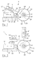
- FIG. 1 of the drawing shows a device 1 designed as a spinning machine for splitting a round blank 5.
- the device 1 has a spindle 2, which is shown in section and which carries the round blank 5 in a rotationally fixed manner by means of a chuck 21, which is covered here.
- the device 1 comprises a splitting and expanding roll 3, which is rotatably mounted on a roll holder 31.
- the axis of rotation 30 of the roller 3 runs parallel to the axis of rotation 20 of the spindle 2.
- the roller 3 can be moved with the roller holder 31 on a support 33 in the radial direction of the round blank 5 in the direction of the arrow 39.
- a part of a machine bed 32 of the device 1 is indicated below the support 33.
- FIG. 1 also shows a laser 4 as a beam generating device, which can be moved on a further support 41 mounted on the roll holder 31 in the direction of the arrow 49.
- a converging energy or laser beam 40 can be generated by means of the laser 4 and strikes the round blank 5 in a focus 40 ′.
- the laser 4 can be adjusted with its support 41 via an adjusting device (not shown) in such a way that the laser beam 40 also essentially always runs in the radial direction of the round blank 5 and is aligned with the base of the gap.
- a prefabricated circular blank 5, here a flat, circular metal disc is first placed on the chuck 21 on the spindle 2 and secured there against rotation, for example by means of a counterholder.
- the spindle 2 is then rotated together with the circular blank 5, as indicated by the arrow 28.
- the laser 40 is switched on, whereby the laser beam 40 is generated with its focus 40 '.
- the split roll 3 is moved to the right to the circumference 50 of the round blank 5 by moving the roll holder 31 on the support 33.
- the laser beam generated by the laser 4 heats and thus softens the metal forming the circular blank 5 at the peripheral region 50 of the circular blank, as a result of which the split roller 3, which is supplied towards the peripheral 50, can comparatively easily penetrate into the metal and thus produce a gap 51.
- the gap 51 is increasingly deepened and widened.
- the laser 4 is seated on the roller holder 31 of the nip roller 3, the focus 40 'of the laser beam 40 is continuously adjusted without further measures so that it always hits the bottom 52 of the groove 51. In this way, an optimal introduction of the thermal energy transmitted by the laser beam 40 into the peripheral region 50 of the round blank 5 is achieved.
- the thermal energy transmitted by the laser beam 40 is introduced relatively close to the area of engagement of the nip roller 3 with the round blank 5, so that premature heat drainage is excluded.
- the round blank 5 can then be machined into a finished workpiece by means of further forming.
- FIG. 2 of the drawing shows two alternative configurations of the device 1, these alternative configurations differing from the device 1 according to FIG. 1 in that the laser 4 or 4 ′ can now be moved independently of the splitting or expanding roller 3.
- the device 1 according to FIG. 2 is also a spinning machine, which is shown schematically here in sections.
- the spindle 2 is again in the right part of the illustration recognizable, on which the blank 5 is arranged non-rotatably.
- the splitting and expanding roll 3 is visible again, which can be moved on its roll holder 31 by means of the support 33 relative to the machine bed 32 in the radial direction of the round blank 5.
- a first laser 4 is shown, which can be moved independently of the roller holder 31 on its own support 43 in the sense of the movement arrows 49.
- the direction of travel is selected perpendicular to the direction of travel of the roller holder 31 and the axis of the spindle 2.
- the position of the laser 4 relative to the circular blank 5 is selected such that the laser beam 40 that can be generated by the laser 4 strikes the circumference 50 of the circular blank 5 essentially tangentially.
- the gap 51 in the circumference 50 of the round blank 5 has already been partially produced, the laser 40 being tracked by methods along its support 43 such that the focus 40 ′ of the laser beam 40 is always on the bottom 52 of the Gap 51 hits.
- FIG. 2 An alternative arrangement and alignment is shown using a second laser 4 'in the upper right part of FIG. 2.
- the laser 4 ' is aligned in the radial direction of the round blank 5 and can be moved in the longitudinal direction and in a direction parallel to the laser beam 40 which it can generate in the direction of the arrow 49.
- Appropriate tracking of the laser 4 'along its own support 43 provided here also ensures that the focus 40' of the laser beam 40 always hits the bottom 52 of the gap 51 in this embodiment.
- the device 1 can also be equipped with two lasers 4 and 4' if necessary.
- the laser beam 40 can not only soften the metal forming the round blank 5, but also, if necessary, liquefy or vaporize it in the areas hit by the laser beam 40 or its focus 40 '.
- the gap 51 in the circumference 50 of the round blank 5 is then generated directly by the laser beam 40, in which case the roller 3 then merely has the function of an expanding roller which widens the gap and thus ensures that the converging laser beam 40 also when the gap 51 deepens, it can reach the bottom 52 of the gap 51 without shading.
- means for removing the liquefied and / or evaporated metal are expediently provided, which are not specifically shown in the drawing.
Landscapes
- Engineering & Computer Science (AREA)
- Mechanical Engineering (AREA)
- Laser Beam Processing (AREA)
Applications Claiming Priority (2)
| Application Number | Priority Date | Filing Date | Title |
|---|---|---|---|
| DE4429801A DE4429801C2 (de) | 1994-08-23 | 1994-08-23 | Verfahren zum Spalten einer Ronde aus Metall und Vorrichtung zur Durchführung des Verfahrens |
| DE4429801 | 1994-08-23 |
Publications (2)
| Publication Number | Publication Date |
|---|---|
| EP0703022A1 true EP0703022A1 (fr) | 1996-03-27 |
| EP0703022B1 EP0703022B1 (fr) | 1998-07-08 |
Family
ID=6526300
Family Applications (1)
| Application Number | Title | Priority Date | Filing Date |
|---|---|---|---|
| EP95113252A Expired - Lifetime EP0703022B1 (fr) | 1994-08-23 | 1995-08-23 | Procédé pour fissurer un rond en métal |
Country Status (2)
| Country | Link |
|---|---|
| EP (1) | EP0703022B1 (fr) |
| DE (2) | DE4429801C2 (fr) |
Families Citing this family (2)
| Publication number | Priority date | Publication date | Assignee | Title |
|---|---|---|---|---|
| US6158261A (en) * | 1997-07-14 | 2000-12-12 | General Electric Company | Mill for producing axially symmetric parts |
| RU2134175C1 (ru) * | 1997-07-14 | 1999-08-10 | Институт проблем сверхпластичности металлов РАН | Стан для изготовления осесимметричных деталей |
Citations (2)
| Publication number | Priority date | Publication date | Assignee | Title |
|---|---|---|---|---|
| BE714551A (fr) * | 1967-05-26 | 1968-09-30 | ||
| EP0451268A1 (fr) * | 1989-10-30 | 1991-10-16 | Asahi Tec Corporation | Installation de moulage en rotation |
Family Cites Families (1)
| Publication number | Priority date | Publication date | Assignee | Title |
|---|---|---|---|---|
| DE4425033C2 (de) * | 1994-07-15 | 1999-07-29 | Fraunhofer Ges Forschung | Verfahren und Vorrichtung zum Drückumformen von Werkstücken |
-
1994
- 1994-08-23 DE DE4429801A patent/DE4429801C2/de not_active Expired - Fee Related
-
1995
- 1995-08-23 DE DE59502748T patent/DE59502748D1/de not_active Expired - Fee Related
- 1995-08-23 EP EP95113252A patent/EP0703022B1/fr not_active Expired - Lifetime
Patent Citations (2)
| Publication number | Priority date | Publication date | Assignee | Title |
|---|---|---|---|---|
| BE714551A (fr) * | 1967-05-26 | 1968-09-30 | ||
| EP0451268A1 (fr) * | 1989-10-30 | 1991-10-16 | Asahi Tec Corporation | Installation de moulage en rotation |
Also Published As
| Publication number | Publication date |
|---|---|
| DE4429801C2 (de) | 1997-06-26 |
| DE4429801A1 (de) | 1996-02-29 |
| DE59502748D1 (de) | 1998-08-13 |
| EP0703022B1 (fr) | 1998-07-08 |
Similar Documents
| Publication | Publication Date | Title |
|---|---|---|
| EP2374569B1 (fr) | Dispositif de traitement au laser et procédé de fabrication d'un outil à rotation symétrique | |
| EP0299111B1 (fr) | Procédé et dispositif de redressage de pièces présentant des parties excentrées | |
| DE2804479A1 (de) | Verfahren und vorrichtung zum bearbeiten eines werkstuecks | |
| EP2691206B1 (fr) | Procédé d'usinage par faisceau laser d'une pièce | |
| EP2794180B1 (fr) | Dispositif de reprofilage d'une aube de turbine à gaz | |
| EP4035823B1 (fr) | Procédé d'usinage par faisceau d'une pièce tabulaire ou tubulaire | |
| EP2314412A2 (fr) | Dispositif de traitement au laser et procédé de fabrication d'une surface sur une ébauche | |
| EP2794181A1 (fr) | Dispositif de correction d'une aube de turbine à gaz | |
| DE60102940T2 (de) | Verfahren und vorrichtung zum trennen von glasgegenständen | |
| DE102005027800A1 (de) | Vorrichtung zum mehrfachen Trennen eines flachen Werkstückes aus einem spröden Material mittels Laser | |
| DE102019202533A1 (de) | Verfahren und Vorrichtung zur Aufbereitung eines Feinbearbeitungswerkzeugs sowie Feinbearbeitungswerkzeug | |
| DE3905551C2 (fr) | ||
| EP0562130B1 (fr) | Dispositif pour la soudure à superposition | |
| DE3850256T2 (de) | Verfahren und Vorrichtung zur Behandlung einer bearbeiteten Fläche eines Werkstücks. | |
| DE29908585U1 (de) | Vorrichtung zur Bearbeitung von Werkstücken aus diamanthaltigen Werkstoffen | |
| EP0703022B1 (fr) | Procédé pour fissurer un rond en métal | |
| DE10248207B4 (de) | Vorrichtung zum Scherschneiden Verwendung dieser Vorrichtung und Verfahren dazu | |
| EP1242322B1 (fr) | Procede et dispositif pour sectionner des pieces plates constituees d'un materiau fragile | |
| EP1593493A1 (fr) | Appareil pour la gravure de cellules en cylindres d'impression au moyen de lumiere laser | |
| DE102016118270A1 (de) | Bremsscheiben-Werkzeug zum Bearbeiten eines Bremsscheiben-Rohlings, Bremsscheiben-Herstellanlage und Verfahren zum Herstellen einer Bremsscheibe | |
| DE102017011495B4 (de) | Kombiniertes Bearbeitungsverfahren und kombiniertes Bearbeitungsprogramm | |
| DE19848033C1 (de) | Vorrichtung zur Randschichthärtung von Werkstücken | |
| EP4580828A1 (fr) | Procédé d'usinage au laser d'une pièce allongée et dispositif d'usinage au laser pour la mise en oeuvre du procédé | |
| EP0907437B1 (fr) | Procede pour laminer des roues coniques sur un laminoir a estamper dans le sens axial et outillage approprie pour mettre ledit procede en oeuvre | |
| EP0086934B1 (fr) | Procédé et cage de laminoir pour laminer des bandes de largeur différente |
Legal Events
| Date | Code | Title | Description |
|---|---|---|---|
| PUAI | Public reference made under article 153(3) epc to a published international application that has entered the european phase |
Free format text: ORIGINAL CODE: 0009012 |
|
| AK | Designated contracting states |
Kind code of ref document: A1 Designated state(s): DE GB |
|
| 17P | Request for examination filed |
Effective date: 19960223 |
|
| GRAG | Despatch of communication of intention to grant |
Free format text: ORIGINAL CODE: EPIDOS AGRA |
|
| 17Q | First examination report despatched |
Effective date: 19971125 |
|
| GRAG | Despatch of communication of intention to grant |
Free format text: ORIGINAL CODE: EPIDOS AGRA |
|
| GRAH | Despatch of communication of intention to grant a patent |
Free format text: ORIGINAL CODE: EPIDOS IGRA |
|
| GRAH | Despatch of communication of intention to grant a patent |
Free format text: ORIGINAL CODE: EPIDOS IGRA |
|
| GRAA | (expected) grant |
Free format text: ORIGINAL CODE: 0009210 |
|
| AK | Designated contracting states |
Kind code of ref document: B1 Designated state(s): DE GB |
|
| RIN1 | Information on inventor provided before grant (corrected) |
Inventor name: KOESTERMEIER, KARL-HEINZ Inventor name: REICHHARDT, HANS H. |
|
| GBT | Gb: translation of ep patent filed (gb section 77(6)(a)/1977) |
Effective date: 19980710 |
|
| REF | Corresponds to: |
Ref document number: 59502748 Country of ref document: DE Date of ref document: 19980813 |
|
| PLBE | No opposition filed within time limit |
Free format text: ORIGINAL CODE: 0009261 |
|
| STAA | Information on the status of an ep patent application or granted ep patent |
Free format text: STATUS: NO OPPOSITION FILED WITHIN TIME LIMIT |
|
| 26N | No opposition filed | ||
| PGFP | Annual fee paid to national office [announced via postgrant information from national office to epo] |
Ref country code: GB Payment date: 20000823 Year of fee payment: 6 |
|
| PGFP | Annual fee paid to national office [announced via postgrant information from national office to epo] |
Ref country code: DE Payment date: 20000830 Year of fee payment: 6 |
|
| PG25 | Lapsed in a contracting state [announced via postgrant information from national office to epo] |
Ref country code: GB Free format text: LAPSE BECAUSE OF NON-PAYMENT OF DUE FEES Effective date: 20010823 |
|
| GBPC | Gb: european patent ceased through non-payment of renewal fee |
Effective date: 20010823 |
|
| PG25 | Lapsed in a contracting state [announced via postgrant information from national office to epo] |
Ref country code: DE Free format text: LAPSE BECAUSE OF NON-PAYMENT OF DUE FEES Effective date: 20020501 |