EP0703032B1 - Frässchneideinsatz und Fräser dafür - Google Patents
Frässchneideinsatz und Fräser dafür Download PDFInfo
- Publication number
- EP0703032B1 EP0703032B1 EP95114667A EP95114667A EP0703032B1 EP 0703032 B1 EP0703032 B1 EP 0703032B1 EP 95114667 A EP95114667 A EP 95114667A EP 95114667 A EP95114667 A EP 95114667A EP 0703032 B1 EP0703032 B1 EP 0703032B1
- Authority
- EP
- European Patent Office
- Prior art keywords
- edge
- cutting edge
- subcutting
- negative land
- cutting
- Prior art date
- Legal status (The legal status is an assumption and is not a legal conclusion. Google has not performed a legal analysis and makes no representation as to the accuracy of the status listed.)
- Expired - Lifetime
Links
Images


Classifications
-
- B—PERFORMING OPERATIONS; TRANSPORTING
- B23—MACHINE TOOLS; METAL-WORKING NOT OTHERWISE PROVIDED FOR
- B23C—MILLING
- B23C5/00—Milling-cutters
- B23C5/02—Milling-cutters characterised by the shape of the cutter
- B23C5/06—Face-milling cutters, i.e. having only or primarily a substantially flat cutting surface
-
- B—PERFORMING OPERATIONS; TRANSPORTING
- B23—MACHINE TOOLS; METAL-WORKING NOT OTHERWISE PROVIDED FOR
- B23C—MILLING
- B23C5/00—Milling-cutters
- B23C5/16—Milling-cutters characterised by physical features other than shape
- B23C5/20—Milling-cutters characterised by physical features other than shape with removable cutter bits or teeth or cutting inserts
- B23C5/202—Plate-like cutting inserts with special form
-
- B—PERFORMING OPERATIONS; TRANSPORTING
- B23—MACHINE TOOLS; METAL-WORKING NOT OTHERWISE PROVIDED FOR
- B23C—MILLING
- B23C5/00—Milling-cutters
- B23C5/16—Milling-cutters characterised by physical features other than shape
- B23C5/20—Milling-cutters characterised by physical features other than shape with removable cutter bits or teeth or cutting inserts
- B23C5/22—Securing arrangements for bits or teeth or cutting inserts
- B23C5/2265—Securing arrangements for bits or teeth or cutting inserts by means of a wedge
- B23C5/2269—Securing arrangements for bits or teeth or cutting inserts by means of a wedge for plate-like cutting inserts
-
- B—PERFORMING OPERATIONS; TRANSPORTING
- B23—MACHINE TOOLS; METAL-WORKING NOT OTHERWISE PROVIDED FOR
- B23C—MILLING
- B23C2200/00—Details of milling cutting inserts
- B23C2200/20—Top or side views of the cutting edge
- B23C2200/201—Details of the nose radius and immediately surrounding areas
-
- B—PERFORMING OPERATIONS; TRANSPORTING
- B23—MACHINE TOOLS; METAL-WORKING NOT OTHERWISE PROVIDED FOR
- B23C—MILLING
- B23C2200/00—Details of milling cutting inserts
- B23C2200/20—Top or side views of the cutting edge
- B23C2200/203—Curved cutting edges
-
- B—PERFORMING OPERATIONS; TRANSPORTING
- B23—MACHINE TOOLS; METAL-WORKING NOT OTHERWISE PROVIDED FOR
- B23C—MILLING
- B23C2215/00—Details of workpieces
- B23C2215/24—Components of internal combustion engines
-
- B—PERFORMING OPERATIONS; TRANSPORTING
- B23—MACHINE TOOLS; METAL-WORKING NOT OTHERWISE PROVIDED FOR
- B23C—MILLING
- B23C2222/00—Materials of tools or workpieces composed of metals, alloys or metal matrices
- B23C2222/14—Cast iron
-
- B—PERFORMING OPERATIONS; TRANSPORTING
- B23—MACHINE TOOLS; METAL-WORKING NOT OTHERWISE PROVIDED FOR
- B23C—MILLING
- B23C2226/00—Materials of tools or workpieces not comprising a metal
- B23C2226/12—Boron nitride
- B23C2226/125—Boron nitride cubic [CBN]
-
- B—PERFORMING OPERATIONS; TRANSPORTING
- B23—MACHINE TOOLS; METAL-WORKING NOT OTHERWISE PROVIDED FOR
- B23C—MILLING
- B23C2228/00—Properties of materials of tools or workpieces, materials of tools or workpieces applied in a specific manner
- B23C2228/49—Sintered
-
- B—PERFORMING OPERATIONS; TRANSPORTING
- B23—MACHINE TOOLS; METAL-WORKING NOT OTHERWISE PROVIDED FOR
- B23C—MILLING
- B23C2240/00—Details of connections of tools or workpieces
- B23C2240/08—Brazed connections
-
- Y—GENERAL TAGGING OF NEW TECHNOLOGICAL DEVELOPMENTS; GENERAL TAGGING OF CROSS-SECTIONAL TECHNOLOGIES SPANNING OVER SEVERAL SECTIONS OF THE IPC; TECHNICAL SUBJECTS COVERED BY FORMER USPC CROSS-REFERENCE ART COLLECTIONS [XRACs] AND DIGESTS
- Y10—TECHNICAL SUBJECTS COVERED BY FORMER USPC
- Y10T—TECHNICAL SUBJECTS COVERED BY FORMER US CLASSIFICATION
- Y10T407/00—Cutters, for shaping
- Y10T407/19—Rotary cutting tool
- Y10T407/1906—Rotary cutting tool including holder [i.e., head] having seat for inserted tool
- Y10T407/1908—Face or end mill
- Y10T407/1924—Specified tool shape
-
- Y—GENERAL TAGGING OF NEW TECHNOLOGICAL DEVELOPMENTS; GENERAL TAGGING OF CROSS-SECTIONAL TECHNOLOGIES SPANNING OVER SEVERAL SECTIONS OF THE IPC; TECHNICAL SUBJECTS COVERED BY FORMER USPC CROSS-REFERENCE ART COLLECTIONS [XRACs] AND DIGESTS
- Y10—TECHNICAL SUBJECTS COVERED BY FORMER USPC
- Y10T—TECHNICAL SUBJECTS COVERED BY FORMER US CLASSIFICATION
- Y10T407/00—Cutters, for shaping
- Y10T407/19—Rotary cutting tool
- Y10T407/1946—Face or end mill
-
- Y—GENERAL TAGGING OF NEW TECHNOLOGICAL DEVELOPMENTS; GENERAL TAGGING OF CROSS-SECTIONAL TECHNOLOGIES SPANNING OVER SEVERAL SECTIONS OF THE IPC; TECHNICAL SUBJECTS COVERED BY FORMER USPC CROSS-REFERENCE ART COLLECTIONS [XRACs] AND DIGESTS
- Y10—TECHNICAL SUBJECTS COVERED BY FORMER USPC
- Y10T—TECHNICAL SUBJECTS COVERED BY FORMER US CLASSIFICATION
- Y10T407/00—Cutters, for shaping
- Y10T407/27—Cutters, for shaping comprising tool of specific chemical composition
Definitions
- the present invention relates to an indexable insert which is clamped into a face milling cutter in face milling of cast-iron parts and a milling cutter employing the same, and more particularly, it relates to an indexable insert for milling which enables ultrahigh-speed milling of cast-iron parts while attaining a long tool life and a milling cutter employing the same.
- the indexable insert for milling according to the present invention attains a remarkable effect particularly when the same is applied to milling of gray cast iron.
- Cast-iron parts such as cylinder blocks and cylinder heads for automobile engines are generally face-milled by cemented carbide inserts, coated inserts, ceramic inserts etc.
- cemented carbide inserts coated inserts, ceramic inserts etc.
- negative land angles 15° and 25° are well known in relation to conventional indexable inserts for milling which are made of cemented carbide and formed by a sintered cubic boron nitride compact (hereinafter referred to as "CBN compact”) respectively.
- CBN compact sintered cubic boron nitride compact
- cemented carbide and coated inserts are utilized at cutting speeds V of about 150 to 250 m/min., while a ceramics insert is utilized at a cutting speed V of about 400 m/min. in practice. If the cutting speeds are increased beyond these ranges, the tool life of the inserts is disadvantageously reduced to increase the working costs.
- the sintered CBN compact is easy to chip since the same is inferior in toughness to other cutting tool materials due to its characteristics, and thermal crack is easily caused due to heat affection.
- the sintered CBN compact is simply applied to a cutting edge, therefore, it may not be possible to attain a sufficient life.
- An object of the present invention is to provide an indexable insert for milling which can excellently finish a machined surface of a workpiece while attaining a sufficient tool life particularly in high-speed cutting of at least 800 m/min., or at least 1000 m/min. and a milling cutter employing the same.
- a indexable insert being clamped into a milling cutter for face milling, comprises
- the cutting edge is hardly affected by heat due to the subcutting edge angle ⁇ of at least 30°, whereby occurrence of thermal crack is prevented. Further, increase of cutting resistance is prevented since the subcutting edge angle ⁇ is not more than 60°, whereby the indexable insert is maintained in excellent sharpness.
- the negative land angle ⁇ of at least 30° and 45° Due to the negative land angle ⁇ of at least 30° and 45°, further, high-speed milling of at least 800 to 1000 m/min. is enabled. While a conventional sintered CBN compact tool has a standard negative land angle ⁇ of 25°, the aforementioned high-speed milling is enabled by increasing the negative land angle ⁇ beyond this standard. While it has generally been regarded as impractical to increase the negative land angle ⁇ since cutting resistance is excessively increased in this case, the present invention enables cutting with a large negative land angle ⁇ in milling at a high speed exceeding 800 m/min., since the strength of a workpiece is rapidly reduced, particularly when the workpiece is made of gray cast iron.
- the negative land width L is set to be at least 0.05 mm, whereby the subcutting edge and the flat drag type cutting edge are inhibited from chipping.
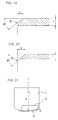
- the negative land width L is set to be not more than 0.40 mm, in order to form a cutting edge ridgeline 8 within the range of a thickness t of a CBN layer as shown in Fig. 19, since the thickness (t shown in Figs. 19 and 20) of a general CBN layer is about 0.8 mm. If the negative land angle ⁇ and the negative land width L are set at 45° and 1.2 mm respectively, for example, the negative land is so excessively increased in size that no actual cutting edge ridgeline 8 is formed on the sintered CBN compact as shown in Fig. 20.
- the sintered CBN compact is so hard that it is difficult to grind the same as compared with cemented carbide etc. If the negative land width L is meaninglessly increased, therefore, the time for grinding the negative land is so extremely increased that the cost for working the indexable insert is disadvantageously increased as the result.
- the aforementioned object of the present invention is attained through the straight shape of the subcutting edge, and no desired effect can be attained if the subcutting edge has a curved shape.
- the contact length between the same and a workpiece can be further reduced as compared with a curved subcutting edge in relation to the same depth of cut.
- the negative land width L of the cutting edge is preferably at least 0.075 mm and not more than 0.30 mm.
- the effect of inhibiting the cutting edge from chipping is further facilitated due to the lower limit of at least 0.075 mm, while the thickness of the CBN layer is further sufficiently ensured to further facilitate the effect of preventing increase of the time for grinding the negative land due to the upper limit of not more than 0.30 mm.
- the flat drag type cutting edge is preferably in the form of a circular arc having a radius of curvature of at least 200 mm and not more than 400 mm, in order to improve machined surface roughness due to such an arcuate shape of the flat drag type cutting edge.
- Fig. 21 shows an exemplary flat drag type cutting edge 4.
- the radius R of curvature of the arcuate tooth profile is set in the range of at least 200 mm and not more than 400 mm for the following reason: If the radius R of curvature of the arcuate tool profile exceeds 400 mm, the contact length between the flat drag type cutting edge 4 and a workpiece is further increased as compared with a cutting edge having a small radius of curvature to increase cutting resistance, leading to occurrence of a chatter phenomenon during cutting. If the radius R of curvature is smaller than 200 mm, on the other hand, machined surface roughness of the workpiece is hardly improved as compared with an indexable insert which is in the form of a straight flat drag.
- indexable insert for milling according to the present invention can also be employed along with a cemented carbide insert and a ceramics insert.
- indexable inserts of different materials can be applied to a milling cutter together.
- the indexable insert according to the present invention is employed as a wiper insert, to attain an effect of improving machined surface roughness of the workpiece.
- the cemented carbide and ceramics inserts are undurable for high-speed milling.
- all of the plurality of indexable inserts which are clamped on the cutter are preferably prepared from the inventive indexable inserts.
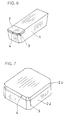
- Fig. 2 shows a typical mode of an indexable insert for milling to which the present invention is applied.
- the indexable insert shown in Fig. 2 consists of a metal base 1 which is made of cemented carbide containing WC and Co, and a sintered CBN compact 2, forming a cutting edge, which is brazed to a portion close to an upper surface corner of the metal base 1.
- the CBN sintered compact 2 has a subcutting edge 3 on an upper edge of its corner portion, and a flat drag type cutting edge 4 is provided in continuation to this subcutting edge 3.
- Figs. 3A and 3B illustrate the metal base 1 and the sintered CBN compact 2 of the indexable insert shown in Fig.
- the sintered CBN compact 2 is formed by a substrate 2a of cemented carbide and a CBN layer 2b which are integrally sintered with each other in a stacked state.
- Figs. 4 and 5 shows other modes of indexable inserts in which cutting edges consisting of sintered CBN compacts are brazed to only portions close to upper surface corners of metal bases.
- Fig. 6 shows a further indexable insert in which a sintered CBN compact 2 is brazed to only an upper surface portion around an end of a metal base 1, made of cemented carbide, which is in the form of an elongated block.
- the present invention is also applicable to an indexable insert formed by a support layer 2a of cemented carbide and a CBN layer 2b consisting of a sintered CBN compact which are integrally sintered with each other, as shown in Fig. 7.
- FIG. 15A is a perspective view of the face milling cutter as viewed along arrow E in Fig. 15A, three-dimensionally showing the indexable inserts which are clamped into the cutter body.
- Fig. 23B is an enlarged view of an edge part B of the indexable insert shown in Fig. 23B, showing a subcutting edge angle ⁇ , a negative land angle ⁇ , a negative land width L and a clearance angle ⁇ of the indexable insert respectively.
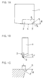
- the cutting edge of a face milling cutter is formed by a subcutting edge 3 and a flat drag 4 as shown in Figs. 1A to 1C, and a negative land is provided as the case may be. It has been proved by the results of the following experiments that setting of a subcutting edge angle ⁇ , a negative land angle ⁇ and a negative land width L has an extremely important meaning when a sintered CBN compact is employed as the cutting edge.
- indexable inserts of the mode shown in Fig. 2 were employed with planar and right side elevational shapes shown in Figs. 1A and 1B respectively.
- the subcutting edge angle ⁇ is defined in Fig. 1A, while the negative land angle ⁇ and the negative land width L are defined in Fig. 1C.
- a clearance angle which is defined by an angle ⁇ shown in Fig. 1B may be either 0° or an acute angle which is in the range of 5° to 20°. In each of the following Examples, the clearance angle ⁇ was set at 15°.
- the subcutting edge 3 had a straight shape.
- the reason for this is explained as follows, on the basis of Figs. 17A to 17C and 18A to 18C:
- a straight shape, an arcuate shape and a combination of straight and arcuate shapes are employable as shown in Figs. 17A to 17C respectively.
- the arcuate subcutting edge shown in Fig. 17B has been mainly employed, and no straight cutting edge has been used in general. Comparing Figs. 18A and 18B with each other, however, it is understood that the contact length l between an arcuate subcutting edge shown in Fig.
- flat drag type cutting edge 4 of the sintered CBN compact 2 may have a straight shape
- arcuate flat drag type cutting edges having radii of curvature of 200 to 400 mm were employed in the following Examples, in order to improve machined surface roughness.
- Example 1 the negative land width L was fixed at 0.2 mm, while the subcutting edge angle ⁇ and the negative land angle ⁇ were varied to carry out experiments.
- two plates 12a and 12b of 25 mm in width and 150 mm in length which were made of gray cast iron (FC 250 in Japanese Industrial Standard) were employed and set as shown in Fig. 22.
- An indexable insert of experiment No. 1 shown in Fig. 8 was first clamped on a face milling cutter 13 of 200 mm in diameter shown in Fig. 22 to carry out cutting for 100 passes under conditions of a cutting speed of 1000 m/min., a feed rate of 0.15 mm/tooth, and a depth of cut of 0.5 mm, and a damaged state of the cutting edge was checked.
- Fig. 8 shows states of the edges of the respective indexable inserts which were damaged as the results of these experiments.
- This figure shows thermal crack of the cutting edges and flank wear conditions
- Figs. 9A and 9B are enlarged views showing such thermal crack and flank wear respectively.
- Fig. 9A shows the state of thermal crack caused on a cutting edge.
- the damaged state of the edge is changed from cracking to chipping as the number of such thermally cracked portions and the depths thereof are increased.
- a longer tool life can be attained as the number of such thermally cracked portions and the depths thereof are reduced.
- Fig. 9B shows flank wear which was caused on the cutting edge while rounding the edge.
- a longer tool life can be attained as the flank wear width is reduced, due to occurrence of no thermal crack. It is understood from the states of the edges damaged as the results of experiments shown in Fig. 8 that occurrence of thermal crack is so gradually suppressed that the number of thermally cracked portions is reduced as the negative land angle ⁇ is increased, regardless of the subcutting edge angle ⁇ .
- the subcutting edge angle ⁇ is in the range of 30° to 60° and the negative land angle ⁇ is in the range of 30° to 45° in a proper edge shape minimizing occurrence of thermal crack and maintaining sharpness of the cutting edge.
- ranges enabling cutting for 180 to 200 passes are 30° to 60° for the subcutting edge angle ⁇ and 30° to 45° for the negative land angle ⁇ respectively. Further, it was possible to attain machined surface roughness of at least 6.3 Z under JIS (Japanese Industrial Standard) by face milling with such a cutting edge.
- JIS Japanese Industrial Standard
- the flank wear width reached 0.2 mm after cutting for 180 to 200 passes since only one indexable insert was clamped into the cutter body.
- at least eight indexable inserts are generally clamped into a cutter. In practice, therefore, at least 8 x 200 passes, i.e., at least 1600 passes can be expected for the tool life.
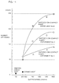
- indexable inserts of cemented carbide (K10), ceramics (Al 2 O 3 -TiC) and sintered CBN compacts were clamped on a face milling cutter of 200 mm in diameter respectively for cutting workpieces at a constant feed rate f of 0.15 mm/tooth and a constant depth of cut d of 0.5 mm and various cutting speeds Vm/min., to check numbers of cutting passes bringing flank wear widths of 0.2 mm.
- the workpieces were identical to those employed in Example 1.
- the sintered CBN compacts were prepared from those employed in experiments Nos. 1, 4 and 8 in Example 1.
- Fig. 11 shows the results of experiments in Example 3.
- flank wear was so quickly caused that the flank wear width reached 0.2 mm after cutting for 5 passes in the indexable insert of cemented carbide cutting the workpiece at a cutting speed of 150 m/min.
- the flank wear width reached 0.2 mm after cutting the workpiece for 10 passes at a cutting speed of 400 m/min.
- each indexable insert of the sintered CBN compact of experiments Nos. 1, 4 and 8 reached a flank wear width of 0.2 mm with 50 to 60 passes at the cutting speed of 400 m/min. which was identical to that for the ceramics indexable insert, and attained a tool life which was 5 to 6 times that of the ceramics indexable insert.
- the lives of these indexable inserts were further increased as the cutting speeds were increased, such that the indexable insert of the sintered CBN compact of experiment No. 8 was capable of cutting the workpiece for 200 passes at the cutting speed of 1500 m/min. and attained a life of 20 and 40 times those of the ceramics and cemented carbide indexable inserts respectively although the indexable inserts of the sintered CBN compacts of experiments Nos. 1 and 4 were chipped by thermal crack at 90 and 140 passes respectively.
- the negative land width L was varied in the range of 0.025 to 0.40 mm in six types of indexable inserts and the feed rate f was varied in the range of 0.05 to 0.30 mm/tooth as shown in Figs. 12A and 12B to check presence/absence of chipping of cutting edges, in order to analyze the proper value of the negative land width L.
- Workpieces identical to those in Example 1 were employed and each of the aforementioned six types of indexable inserts was clamped on a face milling cutter of 200 mm in diameter to cut the workpieces at a cutting speed of 1500 m/min. and a depth of cut of 0.5 mm.
- Fig. 12A shows the results of cutting tests which were made with edges having subcutting edge angles ⁇ of 45° and negative land angles ⁇ of 30°.
- the negative land widths L were 0.025 mm and 0.05 mm, the cutting edges were chipped with respect to all feeds.
- the negative land widths L were in excess of 0.075 mm, on the other hand, occurrence of chipping was suppressed.
- Fig. 12B shows the results of cutting tests which were made with edges having subcutting edge angles ⁇ of 45° and negative land angles ⁇ of 45°. While the cutting edges were not chipped at the negative land widths L of 0.05 mm when the feed rates f were 0.05 mm/edge and 0.10 mm/edge, chipping was caused when the feed rates were in excess of 0.15 mm/edge.
- the negative land width L must be at least 0.05 mm, and preferably at least 0.075 mm, in order to prevent chipping in the normal feed rate range of 0.05 to 0.30 mm/edge.
- the upper limit of the negative land width L no cutting edges were chipped up to 0.4 mm, while the thickness of the CBN layer becomes thinner and the time for grinding the negative land is disadvantageously increased when the negative land width L is increased since the CBN layer of the sintered CBN compact is about 0.8 mm in thickness as already described with reference to Figs. 19 and 20. Therefore, the upper limit of the negative land width L must be not more than 0.4 mm, and preferably not more than 0.3 mm.
- the inventive indexable insert for milling it is possible to suppress chipping resulting from thermal crack by setting the subcutting edge angle, the negative land angle and the negative land width in prescribed ranges respectively while straight forming the subcutting edge. Reduction of sharpness and chipping of the cutting edge resulting from thermal crack are prevented also in high-speed milling of at least 800 m/min. or at least 1000 m/min. so that the tool life can be extended, while an excellent surface finish can be attained with machined surface roughness of a workpiece of at least 6.3 Z under JIS. Consequently, productivity can be remarkably improved in face milling of parts which are made of gray cast iron, in particular.
- the aforementioned indexable insert according to the present invention is applied to every one of a plurality of indexable inserts clamped thereon, whereby the indexable insert can make high-speed cutting and attain excellent machined surface roughness in milling. Consequently, it is possible to provide a milling cutter which remarkably contributes to improvement of productivity in milling of cast iron.
Landscapes
- Engineering & Computer Science (AREA)
- Mechanical Engineering (AREA)
- Milling Processes (AREA)
- Cutting Tools, Boring Holders, And Turrets (AREA)
Claims (10)
- Frässchneideinsatz, welcher in ein Fräswerkzeug zum Stirnfräsen eingespannt ist, umfassend:eine Metallbasis (1), die aus gesintertem Karbid, welches WC und Co enthält, hergestellt ist, und eine Schneidkante (2), welche einen Kompaktkörper aus gesintertem kubischem Bornitrid umfaßt, und auf die Metallbasis (1) hart aufgelötet oder integral mit dieser gesintert ist,wobei die Schneidkante (2) eine Nebenschneidkante (3) mit einem Nebenschneidkantenwinkel (β) von mindestens 30° und höchstens 60° aufweist,und sich in einer flach abgespitzten Schneidkante (4) kontinuierlich fortsetzt und einen negativen Fasenwinkel (Θ) von mindestens 30° und höchstens 45° und eine negative Fasenbreite (L) von mindestens 0,05 mm und höchstens 0,40 mm aufweist,und die Nebenschneidkante (3) eine geradlinige Form besitzt.
- Frässchneideinsatz nach Anspruch 1, bei welchem die negative Fasenbreite (L) der Schneidkante (2) mindestens 0,075 mm und nicht mehr als 0,30 mm beträgt.
- Frässchneideinsatz nach Anspruch 1, bei welchem die flach abgespitzte Schneidkante (4) die Nebenschneidkante (3) der Schneidkante (2) in Form eines Kreisbogens fortsetzt, welcher einen Krümmungsradius von mindestens 200 mm und nicht mehr als 400 mm besitzt.
- Fräswerkzeug zum Stirnfräsen, umfassend eine Mehrzahl von Frässchneideinsätzen, bei welchemjeder einzelne der Mehrzahl von Frässchneideinsätzen umfaßt:eine metallische Basis (1), welche aus gesintertem Karbid, welches WC und Co enthält, hergestellt ist; undeine Schneidkante (2), umfassend einen Kompaktkörper aus gesintertem kubischen Bornitrid, welcher auf die metallische Basis (1) hart aufgelötet oder integral mit dieser gesintert ist, wobei die Schneidkante (2) eine Nebenschneidkante (3) besitzt, welche einen Nebenschneidkantenwinkel (β) von mindestens 30° und nicht mehr als 60°, und eine flach abgespitzte Schneidkante (4), welche sich aus dieser kontinuierlich fortsetzt und einen negativen Fasenwinkel (Θ) von mindestens 30° und nicht mehr als 45° und eine negative Fasenbreite (L) von mindestens 0,05 mm und nicht mehr als 0,40 mm aufweistund die Nebenschneidkante (3) eine geradlinige Form besitzt.
- Fräswerkzeug nach Anspruch 4, bei welchem die negative Fasenbreite (L) der Schneidkante (2) jedes der Mehrzahl von Frässchneideinsätzen mindestens 0,075 mm und nicht mehr als 0,30 mm beträgt.
- Fräswerkzeug nach Anspruch 4, bei welchem die flach abgespitzte Schneidkante (4) sich kontinuierlich aus der Nebenschneidkante (3) der Schneidkante (2) bei jedem der Mehrzahl von Frässchneideinsätzen in Form eines Kreisbogens mit einem Krümmungsradius von mindestens 200 mm und nicht mehr als 400 mm fortsetzt.
- Fräswerkzeug zum Stirnfräsen, umfassend eine Mehrzahl von Frässchneideinsätzen, bei welchemein Teil der Mehrzahl von Frässchneideinsätzen umfaßt:eine metallische Basis (1), welche aus gesintertem Karbid, welches WC und Co enthält, hergestellt ist; undeine Schneidkante (2), umfassend einen Kompaktkörper aus gesintertem kubischen Bornitrid, welcher auf die metallische Basis (1) hart aufgelötet oder integral mit dieser gesintert ist,wobei die Schneidkante (2) eine Nebenschneidkante (3) mit einem Nebenschneidkantenwinkel (β) von mindestens 30° und nicht mehr als 60° und eine flach abgespitzte Schneidkante (4), welche sich aus dieser kontinuierlich fortsetzt, und einen negativen Fasenwinkel (Θ) von mindestens 30° und nicht mehr als 45°, und eine negative Fasenbreite (L) von mindestens 0,05 mm und nicht mehr als 0,40 mm aufweist, und die Nebenschneidkante (3) eine geradlinige Form besitzt.
- Fräswerkzeug nach Anspruch 7, bei welchem die negative Fasenbreite (L) der Schneidkante (2) mindestens 0,075 mm und nicht mehr als 0,30 mm beträgt.
- Fräswerkzeug nach Anspruch 7, bei welchem die flach abgespitzte Schneidkante (4) sich kontinuierlich aus der Nebenschneidkante (3) der Schneidkante (2) in Form eines Kreisbogens mit einem Krümmungsradius von mindestens 200 mm und nicht mehr als 400 mm fortsetzt.
- Fräswerkzeug nach Anspruch 7, bei welchem gesinterte Karbideinsätze und/oder Keramikeinsätze ebenfalls als solche der Mehrzahl von Frässchneideinsätzen verwendet werden.
Applications Claiming Priority (4)
| Application Number | Priority Date | Filing Date | Title |
|---|---|---|---|
| JP227957/94 | 1994-09-22 | ||
| JP22795794 | 1994-09-22 | ||
| JP7163769A JP2751873B2 (ja) | 1994-09-22 | 1995-06-29 | フライス用スローアウェイチップおよびそれを用いたフライス用カッタ |
| JP163769/95 | 1995-06-29 |
Publications (2)
| Publication Number | Publication Date |
|---|---|
| EP0703032A1 EP0703032A1 (de) | 1996-03-27 |
| EP0703032B1 true EP0703032B1 (de) | 1999-04-07 |
Family
ID=26489120
Family Applications (1)
| Application Number | Title | Priority Date | Filing Date |
|---|---|---|---|
| EP95114667A Expired - Lifetime EP0703032B1 (de) | 1994-09-22 | 1995-09-18 | Frässchneideinsatz und Fräser dafür |
Country Status (6)
| Country | Link |
|---|---|
| US (1) | US5707185A (de) |
| EP (1) | EP0703032B1 (de) |
| JP (1) | JP2751873B2 (de) |
| KR (1) | KR0175177B1 (de) |
| AT (1) | ATE178517T1 (de) |
| DE (1) | DE69508873T2 (de) |
Families Citing this family (49)
| Publication number | Priority date | Publication date | Assignee | Title |
|---|---|---|---|---|
| JPH10277831A (ja) * | 1997-04-04 | 1998-10-20 | Sumitomo Electric Ind Ltd | フライス用切削工具 |
| US6224473B1 (en) | 1997-08-07 | 2001-05-01 | Norton Company | Abrasive inserts for grinding bimetallic components |
| EP1006091A4 (de) | 1998-05-22 | 2004-08-04 | Sumitomo Electric Industries | Gesinterter schneidwerzeugkörper aus bornitrid des kubischen systems |
| FR2789613B1 (fr) * | 1999-02-17 | 2001-05-04 | Peugeot Citroen Automobiles Sa | Procede de surfacage d'un objet, notamment d'un bloc-cylindres, et fraise pour la mise en oeuvre de ce procede |
| JP2000280103A (ja) * | 1999-03-29 | 2000-10-10 | Ngk Spark Plug Co Ltd | 切削工具及びホルダ付工具 |
| US6599062B1 (en) * | 1999-06-11 | 2003-07-29 | Kennametal Pc Inc. | Coated PCBN cutting inserts |
| US6939090B1 (en) * | 1999-08-17 | 2005-09-06 | Mitsubishi Materials Corporation | Throwaway tip and throwaway-type cutting tool |
| JP3378575B2 (ja) | 2000-10-27 | 2003-02-17 | 住友電気工業株式会社 | フライスカッタ |
| KR100412161B1 (ko) * | 2000-12-01 | 2003-12-24 | 박승복 | 적층세라믹 콘덴서의 절단장치 |
| DE10258133A1 (de) * | 2002-11-29 | 2004-06-24 | MAPAL Fabrik für Präzisionswerkzeuge Dr. Kress KG | Schneidplatte |
| JP2005111651A (ja) * | 2003-09-19 | 2005-04-28 | Tungaloy Corp | チップおよびフライスカッタおよびそれらを用いた加工方法 |
| JP4704212B2 (ja) * | 2004-01-14 | 2011-06-15 | 住友電工ハードメタル株式会社 | スローアウェイチップ |
| US20050271483A1 (en) * | 2004-06-02 | 2005-12-08 | Sandvik Ab | Indexable cutting inserts and methods for producing the same |
| JP4653744B2 (ja) * | 2005-03-16 | 2011-03-16 | 住友電工ハードメタル株式会社 | 高品位・高能率加工用cbn切削工具 |
| SE0501978L (sv) * | 2005-09-05 | 2007-03-06 | Scania Cv Ab | Förfarande för hantering av en komponent anpassad för användning i ett fordon eller en motor |
| AU2006325088A1 (en) * | 2005-12-12 | 2007-06-21 | Element Six (Production) (Pty) Ltd | PCBN cutting tool components |
| US7510353B2 (en) * | 2006-02-16 | 2009-03-31 | Remark Technologies, Inc. | Indexable cutting tool insert and cutting tool |
| US8287213B2 (en) * | 2006-02-16 | 2012-10-16 | Remark Technologies, Inc. | Indexable cutting tool insert for cutting tools |
| JP5055869B2 (ja) * | 2006-07-21 | 2012-10-24 | 株式会社タンガロイ | スローアウェイ式回転工具 |
| US8454274B2 (en) | 2007-01-18 | 2013-06-04 | Kennametal Inc. | Cutting inserts |
| US9101985B2 (en) | 2007-01-18 | 2015-08-11 | Kennametal Inc. | Cutting insert assembly and components thereof |
| US8439608B2 (en) * | 2007-01-18 | 2013-05-14 | Kennametal Inc. | Shim for a cutting insert and cutting insert-shim assembly with internal coolant delivery |
| US8727673B2 (en) | 2007-01-18 | 2014-05-20 | Kennametal Inc. | Cutting insert with internal coolant delivery and surface feature for enhanced coolant flow |
| US7625157B2 (en) * | 2007-01-18 | 2009-12-01 | Kennametal Inc. | Milling cutter and milling insert with coolant delivery |
| US7883299B2 (en) * | 2007-01-18 | 2011-02-08 | Kennametal Inc. | Metal cutting system for effective coolant delivery |
| US20080175679A1 (en) * | 2007-01-18 | 2008-07-24 | Paul Dehnhardt Prichard | Milling cutter and milling insert with core and coolant delivery |
| US7963729B2 (en) | 2007-01-18 | 2011-06-21 | Kennametal Inc. | Milling cutter and milling insert with coolant delivery |
| US8328471B2 (en) | 2007-01-18 | 2012-12-11 | Kennametal Inc. | Cutting insert with internal coolant delivery and cutting assembly using the same |
| JP5151361B2 (ja) * | 2007-03-12 | 2013-02-27 | 三菱マテリアル株式会社 | ねじ切り切削用インサート |
| DE102007019933A1 (de) * | 2007-04-27 | 2008-10-30 | Kennametal Inc. | Schneidenträger mit aufgelötetem Schneidkörper und Fräsmesserkopf |
| US7955032B2 (en) * | 2009-01-06 | 2011-06-07 | Kennametal Inc. | Cutting insert with coolant delivery and method of making the cutting insert |
| US8083442B2 (en) * | 2009-06-30 | 2011-12-27 | Sae Magnetics (H.K.) Ltd. | Cutting tool for lapping plate |
| DE102010000640A1 (de) * | 2010-03-04 | 2011-09-08 | Gühring Ohg | Stirnfräser |
| EP2593255B1 (de) * | 2010-07-13 | 2016-10-12 | Element Six Limited | Herstellungsverfahren für eine konstruktion einer wendeschneidplatte |
| US8827599B2 (en) | 2010-09-02 | 2014-09-09 | Kennametal Inc. | Cutting insert assembly and components thereof |
| US8734062B2 (en) | 2010-09-02 | 2014-05-27 | Kennametal Inc. | Cutting insert assembly and components thereof |
| KR101838238B1 (ko) | 2011-01-27 | 2018-03-13 | 대구텍 유한회사 | 접선방향 절삭 인서트 |
| US8507082B2 (en) | 2011-03-25 | 2013-08-13 | Kennametal Inc. | CVD coated polycrystalline c-BN cutting tools |
| US8696264B2 (en) | 2012-01-31 | 2014-04-15 | Kennametal Inc. | Modular cutting insert and method of making same |
| US9028953B2 (en) | 2013-01-11 | 2015-05-12 | Kennametal Inc. | CVD coated polycrystalline c-BN cutting tools |
| US10315258B2 (en) | 2014-02-26 | 2019-06-11 | Tungaloy Corporation | Cutting insert and cutting tool |
| JP2016007663A (ja) * | 2014-06-24 | 2016-01-18 | 住友電工ハードメタル株式会社 | 切削インサート |
| EP3167991A4 (de) * | 2014-07-10 | 2017-07-26 | Sumitomo Electric Hardmetal Corp. | Schneideeinsatz und oberflächenfräser damit |
| JP6457257B2 (ja) * | 2014-12-18 | 2019-01-23 | Dmg森精機株式会社 | フライス工具、及びこれを用いた加工方法 |
| CN107252917A (zh) * | 2017-07-12 | 2017-10-17 | 北京沃尔德金刚石工具股份有限公司 | 一种可转位面铣刀片以及使用该刀片的面铣刀头 |
| USD910094S1 (en) | 2018-09-11 | 2021-02-09 | Sumitomo Electric Hardmetal Corp. | Cutting tool |
| CN119973195A (zh) * | 2020-03-30 | 2025-05-13 | 上海名古屋精密工具股份有限公司 | 坯体以及具有螺旋状超硬材料前刀面的切削工具 |
| US12599976B2 (en) * | 2021-07-08 | 2026-04-14 | Kanefusa Kabushiki Kaisha | Rotary cutting tool |
| CN120112381A (zh) * | 2022-11-07 | 2025-06-06 | 兼房株式会社 | 切削刀片及旋转切削工具 |
Family Cites Families (12)
| Publication number | Priority date | Publication date | Assignee | Title |
|---|---|---|---|---|
| JPS60175516U (ja) * | 1984-04-28 | 1985-11-20 | 三菱マテリアル株式会社 | 転削工具用スロ−アウエイチツプ |
| JPS61100302A (ja) * | 1984-10-22 | 1986-05-19 | Hiroshi Eda | ウルツ鉱型窒化硼素焼結体切削工具刃先のランド形成方法 |
| JPS61159314A (ja) * | 1984-12-29 | 1986-07-19 | Mitsubishi Metal Corp | スロ−アウエイ式転削工具 |
| KR920010888B1 (ko) * | 1985-03-30 | 1992-12-21 | 미쓰비시 마테리알 가부시기가이샤 | 심은날 회전 밀링커터(insert rotary cutter) |
| SE448431B (sv) * | 1985-07-03 | 1987-02-23 | Santrade Ltd | Vendsker for spanavskiljande bearbetning |
| US4714385A (en) * | 1986-02-27 | 1987-12-22 | General Electric Company | Polycrystalline diamond and CBN cutting tools |
| US4966500A (en) * | 1987-09-16 | 1990-10-30 | Mitsubishi Kinzoku Kabushiki Kaisha | Face milling cutter with cutter inserts |
| DE4013717A1 (de) * | 1989-10-07 | 1991-04-18 | Sandvik Gmbh | Fraeskopf |
| US5141367A (en) * | 1990-12-18 | 1992-08-25 | Kennametal, Inc. | Ceramic cutting tool with chip control |
| US5120327A (en) * | 1991-03-05 | 1992-06-09 | Diamant-Boart Stratabit (Usa) Inc. | Cutting composite formed of cemented carbide substrate and diamond layer |
| US5188489A (en) * | 1991-05-31 | 1993-02-23 | Kennametal Inc. | Coated cutting insert |
| DE4341503A1 (de) * | 1993-12-06 | 1995-06-08 | Beck August Gmbh Co | Vorrichtung zum Feinbearbeiten von Bohrungen |
-
1995
- 1995-06-29 JP JP7163769A patent/JP2751873B2/ja not_active Expired - Lifetime
- 1995-09-12 US US08/527,107 patent/US5707185A/en not_active Expired - Lifetime
- 1995-09-18 DE DE69508873T patent/DE69508873T2/de not_active Expired - Lifetime
- 1995-09-18 AT AT95114667T patent/ATE178517T1/de not_active IP Right Cessation
- 1995-09-18 EP EP95114667A patent/EP0703032B1/de not_active Expired - Lifetime
- 1995-09-20 KR KR1019950030846A patent/KR0175177B1/ko not_active Expired - Fee Related
Also Published As
| Publication number | Publication date |
|---|---|
| DE69508873D1 (de) | 1999-05-12 |
| ATE178517T1 (de) | 1999-04-15 |
| JPH08141822A (ja) | 1996-06-04 |
| KR0175177B1 (ko) | 1999-02-18 |
| KR960010142A (ko) | 1996-04-20 |
| DE69508873T2 (de) | 1999-08-12 |
| JP2751873B2 (ja) | 1998-05-18 |
| US5707185A (en) | 1998-01-13 |
| EP0703032A1 (de) | 1996-03-27 |
Similar Documents
| Publication | Publication Date | Title |
|---|---|---|
| EP0703032B1 (de) | Frässchneideinsatz und Fräser dafür | |
| CN1240509C (zh) | 具有弯曲切削刃的切削刀片 | |
| EP1231004B1 (de) | Schneideinsatz | |
| US9446460B2 (en) | Cutting insert for high feed face milling | |
| KR101591660B1 (ko) | 날끝 교환식 회전 공구 | |
| EP1226892B1 (de) | Schneidwerkzeug | |
| EP1125667B1 (de) | Kugelkopffräser | |
| CN101460276A (zh) | 切削工具和切削刀片 | |
| CN1196695A (zh) | 铣削刀片 | |
| JP2000308908A (ja) | 切削工具 | |
| CN114951719A (zh) | 切削刀片 | |
| JP2949973B2 (ja) | スローアウェイチップ | |
| JP4959042B2 (ja) | Tランド挿入体 | |
| JP3036343B2 (ja) | エンドミル | |
| KR20210127149A (ko) | 금속 절삭을 위한 선삭 인서트 | |
| EP3461577A1 (de) | Schneidwerkzeug | |
| JP2000071110A (ja) | スローアウェイチップ | |
| CN103317158B (zh) | 用于硬切削加工的陶瓷的刀片 | |
| JP2004154892A (ja) | スローアウェイチップ及び切削工具 | |
| JP2000094210A (ja) | スローアウェイ式穴明け工具 | |
| JP2558412Y2 (ja) | スローアウェイチップ | |
| JPS59175905A (ja) | スロ−アウェイチップ | |
| HK1129342A (en) | A cutting insert and a milling cutter tool for high feed face milling |
Legal Events
| Date | Code | Title | Description |
|---|---|---|---|
| PUAI | Public reference made under article 153(3) epc to a published international application that has entered the european phase |
Free format text: ORIGINAL CODE: 0009012 |
|
| AK | Designated contracting states |
Kind code of ref document: A1 Designated state(s): AT DE FR GB IT SE |
|
| 17P | Request for examination filed |
Effective date: 19960415 |
|
| GRAG | Despatch of communication of intention to grant |
Free format text: ORIGINAL CODE: EPIDOS AGRA |
|
| 17Q | First examination report despatched |
Effective date: 19980731 |
|
| GRAG | Despatch of communication of intention to grant |
Free format text: ORIGINAL CODE: EPIDOS AGRA |
|
| GRAH | Despatch of communication of intention to grant a patent |
Free format text: ORIGINAL CODE: EPIDOS IGRA |
|
| GRAH | Despatch of communication of intention to grant a patent |
Free format text: ORIGINAL CODE: EPIDOS IGRA |
|
| GRAA | (expected) grant |
Free format text: ORIGINAL CODE: 0009210 |
|
| AK | Designated contracting states |
Kind code of ref document: B1 Designated state(s): AT DE FR GB IT SE |
|
| REF | Corresponds to: |
Ref document number: 178517 Country of ref document: AT Date of ref document: 19990415 Kind code of ref document: T |
|
| REF | Corresponds to: |
Ref document number: 69508873 Country of ref document: DE Date of ref document: 19990512 |
|
| ET | Fr: translation filed | ||
| PLBE | No opposition filed within time limit |
Free format text: ORIGINAL CODE: 0009261 |
|
| STAA | Information on the status of an ep patent application or granted ep patent |
Free format text: STATUS: NO OPPOSITION FILED WITHIN TIME LIMIT |
|
| 26N | No opposition filed | ||
| REG | Reference to a national code |
Ref country code: GB Ref legal event code: IF02 |
|
| PGFP | Annual fee paid to national office [announced via postgrant information from national office to epo] |
Ref country code: AT Payment date: 20020911 Year of fee payment: 8 |
|
| PGFP | Annual fee paid to national office [announced via postgrant information from national office to epo] |
Ref country code: FR Payment date: 20030909 Year of fee payment: 9 |
|
| PGFP | Annual fee paid to national office [announced via postgrant information from national office to epo] |
Ref country code: GB Payment date: 20030917 Year of fee payment: 9 |
|
| PG25 | Lapsed in a contracting state [announced via postgrant information from national office to epo] |
Ref country code: AT Free format text: LAPSE BECAUSE OF NON-PAYMENT OF DUE FEES Effective date: 20030918 |
|
| PG25 | Lapsed in a contracting state [announced via postgrant information from national office to epo] |
Ref country code: GB Free format text: LAPSE BECAUSE OF NON-PAYMENT OF DUE FEES Effective date: 20040918 |
|
| GBPC | Gb: european patent ceased through non-payment of renewal fee |
Effective date: 20040918 |
|
| PG25 | Lapsed in a contracting state [announced via postgrant information from national office to epo] |
Ref country code: FR Free format text: LAPSE BECAUSE OF NON-PAYMENT OF DUE FEES Effective date: 20050531 |
|
| REG | Reference to a national code |
Ref country code: FR Ref legal event code: ST |
|
| PG25 | Lapsed in a contracting state [announced via postgrant information from national office to epo] |
Ref country code: IT Free format text: LAPSE BECAUSE OF NON-PAYMENT OF DUE FEES Effective date: 20050918 |
|
| PGFP | Annual fee paid to national office [announced via postgrant information from national office to epo] |
Ref country code: SE Payment date: 20120911 Year of fee payment: 18 |
|
| REG | Reference to a national code |
Ref country code: SE Ref legal event code: EUG |
|
| PG25 | Lapsed in a contracting state [announced via postgrant information from national office to epo] |
Ref country code: SE Free format text: LAPSE BECAUSE OF NON-PAYMENT OF DUE FEES Effective date: 20130919 |
|
| PGFP | Annual fee paid to national office [announced via postgrant information from national office to epo] |
Ref country code: DE Payment date: 20140911 Year of fee payment: 20 |
|
| REG | Reference to a national code |
Ref country code: DE Ref legal event code: R071 Ref document number: 69508873 Country of ref document: DE |