EP0703043A1 - Bohrhammer mit geneigter Kupplungsscheibe - Google Patents
Bohrhammer mit geneigter Kupplungsscheibe Download PDFInfo
- Publication number
- EP0703043A1 EP0703043A1 EP95306676A EP95306676A EP0703043A1 EP 0703043 A1 EP0703043 A1 EP 0703043A1 EP 95306676 A EP95306676 A EP 95306676A EP 95306676 A EP95306676 A EP 95306676A EP 0703043 A1 EP0703043 A1 EP 0703043A1
- Authority
- EP
- European Patent Office
- Prior art keywords
- spindle
- hammer
- clutch plate
- mode
- clutch
- Prior art date
- Legal status (The legal status is an assumption and is not a legal conclusion. Google has not performed a legal analysis and makes no representation as to the accuracy of the status listed.)
- Granted
Links
- 238000003491 array Methods 0.000 abstract description 4
- 238000004519 manufacturing process Methods 0.000 description 2
- 239000000463 material Substances 0.000 description 2
- 230000013011 mating Effects 0.000 description 2
- 239000011449 brick Substances 0.000 description 1
- 239000004567 concrete Substances 0.000 description 1
- 238000010276 construction Methods 0.000 description 1
- 239000002184 metal Substances 0.000 description 1
- 230000004048 modification Effects 0.000 description 1
- 238000012986 modification Methods 0.000 description 1
- 239000004570 mortar (masonry) Substances 0.000 description 1
- 239000002023 wood Substances 0.000 description 1
Images



Classifications
-
- B—PERFORMING OPERATIONS; TRANSPORTING
- B25—HAND TOOLS; PORTABLE POWER-DRIVEN TOOLS; MANIPULATORS
- B25D—PERCUSSIVE TOOLS
- B25D16/00—Portable percussive machines with superimposed rotation, the rotational movement of the output shaft of a motor being modified to generate axial impacts on the tool bit
- B25D16/006—Mode changers; Mechanisms connected thereto
-
- B—PERFORMING OPERATIONS; TRANSPORTING
- B25—HAND TOOLS; PORTABLE POWER-DRIVEN TOOLS; MANIPULATORS
- B25D—PERCUSSIVE TOOLS
- B25D16/00—Portable percussive machines with superimposed rotation, the rotational movement of the output shaft of a motor being modified to generate axial impacts on the tool bit
-
- B—PERFORMING OPERATIONS; TRANSPORTING
- B25—HAND TOOLS; PORTABLE POWER-DRIVEN TOOLS; MANIPULATORS
- B25D—PERCUSSIVE TOOLS
- B25D2211/00—Details of portable percussive tools with electromotor or other motor drive
- B25D2211/06—Means for driving the impulse member
- B25D2211/062—Cam-actuated impulse-driving mechanisms
- B25D2211/064—Axial cams, e.g. two camming surfaces coaxial with drill spindle
-
- B—PERFORMING OPERATIONS; TRANSPORTING
- B25—HAND TOOLS; PORTABLE POWER-DRIVEN TOOLS; MANIPULATORS
- B25D—PERCUSSIVE TOOLS
- B25D2211/00—Details of portable percussive tools with electromotor or other motor drive
- B25D2211/06—Means for driving the impulse member
- B25D2211/062—Cam-actuated impulse-driving mechanisms
- B25D2211/067—Cam-actuated impulse-driving mechanisms wherein the cams are involved in a progressive mutual engagement with increasing pressure of the tool to the working surface
Definitions
- This invention relates to a hammer drill selectively operable in a hammer drill mode and a drill mode.
- hammer drills operate in two modes, namely, a hammer drill mode and a drill mode.
- a hammer drill mode a hammer bit is rotatably driven and axially reciprocated to drill holes in hard brittle materials such as brick, mortar and concrete.
- a drill bit is rotatably driven only, to drill holes in softer, less brittle materials such as wood and metal.
- the hammer drill contains a forwardly spring biased output spindle and a normally disengaged hammer clutch consisting of an input clutch plate and an output clutch plate. The plates have mutually opposed sets of teeth to reciprocate the spindle axially when the clutch is engaged.
- the output clutch plate is axially and rotatably fixed to the output spindle.
- the input clutch plate is axially and non-rotatably fixed in the housing and is engageable by the output clutch plate when an operator applies a rearward bias to the output spindle when engaging a hammer bit with a workpiece.
- the output clutch plate is rotatably driven through a gear train, the output clutch plate is axially reciprocated by the ratcheting of the output clutch plate teeth over the fixed teeth of the input clutch plate.
- the output spindle In the drill mode, the output spindle is locked in the forwardly spring biased position and, the input and output clutch plates are fixed in a disengaged position regardless of the rearward bias applied to the output spindle by an operator. As the result, the output spindle is rotatably driven only.
- Housings for such hammer drills are generally of two types.
- One type is a clam shell housing comprising two clam shell housing halves joined generally along an interface lying in a plane parallel to the axis of the output spindle.
- a second housing type is a jam pot housing comprising two housing halves joined along an interface lying generally in a plane perpendicular to the output spindle.
- the internal components are loaded into one clam shell half and then the second clam shell half is mounted over the components and first clam shell half.
- the components are end loaded into the front and rear housing portions which are generally barrel shaped. Then the two housing halves and the components assembled into each are attached together.
- Tools with a clam shell housing are generally considered to be lower in cost and easier to assemble than tools with a jam pot housing.
- Clam shell housings have, therefore, become widely used for high volume mass produced portable power tools.
- the present invention is directed to a hammer drill comprising a forwardly spring biased output spindle rotatably driven by a motor and axially slidably mounted in the tool housing.
- a mode selector is engageable with the spindle for locking the spindle against the axial movement in the drill mode setting and is disengageable with the spindle for permitting the spindle to be axially slidable in the hammer mode setting.
- a hammer clutch includes first and second clutch plates. The first clutch plate is fixed to and rotatable with the output spindle and has a first tooth array on a rear face transverse to the spindle axis.
- the second clutch plate is fixed to the housing and has a second tooth array on a forwardly inclined front face opposed to the rear face of the first plate.
- the first and second tooth arrays are engageable in the hammer mode setting when an operator applied rearward bias is applied to the spindle when a drill bit is pushed against a workpiece.
- the rear face is shiftable in use in the hammer mode to be generally parallel to the front face.
- the forward inclination of the front face of the second clutch plate compensates for the movement of the rear face from a no-load to a load position so that the faces of the two clutch plates may be generally parallel in use. If misaligned in use, the plates would only engage in a limited region of the tooth arrays and would wear excessively in this region. As a result of the present invention, the hammer clutch has a significantly improved life.
- the front face is preferably inclined at about a 1° angle relative to a line perpendicular to the no-load spindle axis.
- the output spindle is rotatable driven through a first spur gear formed on the periphery of the first clutch plate.
- the hammer drill preferably comprises two clam shell halves joined generally in a plane extending parallel to the spindle axis.
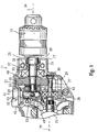
- FIG. 1 A preferred embodiment of a hammer drill in accordance with the present invention is illustrated in Figures 1-3.
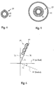
- Figures 4 and 5 illustrate details for the embodiment of Figures 1 to 3.
- Figures 6 and 7 are a schematics to illustrate the operation of the embodiment.
- a hammer drill 11 is operable in two modes of operation, namely, a hammer drill mode and a drill mode.
- a bit (not shown) mounted in a chuck 13 is rotatably driven and is axially reciprocated.
- the bit In the drill mode, the bit is rotatably driven but is not axially reciprocated.
- hammer drill 11 comprises a housing 15.
- Housing 15 is preferably a clam shell housing formed of two clam shell halves 17, 19 joined along an axially extending interface 21.
- other housing types such as a jam pot housing may be used.
- a motor 23 ( Figures 1, 3) is provided in housing 15 for driving an output spindle 25.
- Motor 23 is preferably a universal motor but other motor types may be used.
- motor 23 has an armature shaft 27 having a spur gear 29 formed at its distal end.
- Spur gear 29 drives output shaft 25 through an intermediate spur gear 31 axially and rotatably fixed to output spindle 25.
- output spindle 25 ( Figure 3) is axially slidable and rotatably mounted in housing 15 about a no-load spindle axis 34.
- spindle 25 is rotatably and slidably mounted in a pair of spaced bearings 32, 33.
- spur gear 31 is freely axial slidable relative to spur gear 29.
- hammer drill 11 further comprises a spring 35 for forwardly biasing spindle 25 and gear 31 to the location shown in Figure 3.
- spring 35 is a coil spring located in a housing cavity 37 coaxially of shaft 25.
- Spring 35 is located between bearing 33 fixed in housing 15 and an enlarged shaft segment 39. Forward travel of shaft 25 in housing 15 is limited by a hub 40 formed on spur gear 31 and engageable with axially fixed bearing 33.
- a mode selector 41 ( Figures 2, 3) is engageable with spindle 25 for locking spindle 25 against axial movement in the drill mode setting and is disengageable with spindle 25 for permitting spindle 25 to be axially slidable in the hammer mode setting.
- Figures 2, 3 illustrate the drill mode.
- Mode selector 41 preferably comprises a knob 43 fixed to a cylindrical control shaft 45 rotatably supported in a cavity 47 of bearing block 49.
- Shaft 45 has a recess 53 for selectively receiving a hemispherical end 51 of spindle 25 when selector 41 is set to the hammer drill mode.
- spindle 25 may be axially reciprocated and rearwardly biased by an operator during operation in the hammer drill mode.
- selector 41 is set to the drill mode, recess 53 and spindle end 51 are misaligned to lock shaft 25 in the forwardly biased position shown in Figure 3.
- hammer drill 11 further comprises a hammer clutch 55 comprising first (output) and second (input) clutch plates 57, 59.
- Plate 57 is axially and rotatably fixed to spindle 25 and has a rear face 61 transverse to spindle axis 34 and a first tooth array 63 on rear face 61.
- Second clutch plate 59 is fixed in housing 15 and has a front face opposed to rear face 61 and has a second tooth array 67 on the front face 65.
- a rear face 68 of plate 59 preferably extends perpendicular to no load spindle axis 34.
- the second tooth array 67 is engageable with the first tooth array 63 when rearward bias is applied to spindle 25 and mode selector 41 is in the hammer mode setting. Tooth arrays 63, 67 ( Figures 4, 5) are preferably annular.
- the front face 65 of second plate 59 is forwardly inclined.
- the rear face 61 of first plate 57 is shiftable in use in the hammer drill mode to be generally parallel to front face 65.
- the tips 69 of the second tooth array 67 define a plane 70 forming a small positive angle 71 in a rectangular coordinate system formed by no-load spindle axis 34 and a line 73 perpendicular to the spindle axis 34.
- angle 71 is between about .75 and 1.25 degrees and is optimally about 1°.
- angle 71 is determined empirically by measuring the angle 75 through which spindle axis 34 and output clutch plate 59 are shifted under load by operator applied bias in the hammer drill mode. As illustrated in Figure 6, angle 75 is measured between the no-load spindle axis 34 and the loaded spindle axis 34'. Plate 59 is shifted through an equivalent angle (not shown). Preferably, spur gear 31 and output clutch plate 57 are formed in one piece for reduced cost and compactness. Similarly, output shaft 25 and supporting bearing 32 are located coaxially in fixed input clutch plate 59.
- hammer drill 11 may be set for operation either in a hammer drill mode or in a drill mode by mode selector 41.
- output spindle 25 is rotatably driven and is axially reciprocated.
- spindle 25 is rotatably driven but not axially reciprocated.
- selector 41 is set to the hammer drill mode, recess 53 is aligned to selectively receive spindle end 51.
- spindle 25 may be axially reciprocated and rearwardly biased by an operator for engagement of clutch plates 57, 59.
- Rearward bias is applied to spindle 25 when an operator pushes a hammer bit (not shown) against a workpiece to be drilled.
- spindle 25 and output clutch plate 57 are rotated relative to fixed input clutch plate 59 rearwardly facing tooth array 63 ratchets over forwardly facing tooth array 67 to provide an axially reciprocating hammer action to output spindle 25.
- selector 41 is set to the drill mode, recess 53 and bearing 51 are misaligned and spindle 25 is locked in the position shown in Figures 1-3 by the cylindrical surface of shaft 45 to prevent axial movement of spindle 25.
- the present invention may also find application in hammer drills using a jam pot housing to the extent that tilting of the output spindle axis is encountered under load.
- Such a construction apparently provides a more secure mounting than in a clam shell housing and, therefore, gives rise to less misalignment of the clutch plates under load.
Landscapes
- Engineering & Computer Science (AREA)
- Mechanical Engineering (AREA)
- Percussive Tools And Related Accessories (AREA)
- Drilling And Boring (AREA)
Applications Claiming Priority (2)
| Application Number | Priority Date | Filing Date | Title |
|---|---|---|---|
| US312337 | 1994-09-26 | ||
| US08/312,337 US5628374A (en) | 1994-09-26 | 1994-09-26 | Hammer drill with inclined clutch plate |
Publications (2)
| Publication Number | Publication Date |
|---|---|
| EP0703043A1 true EP0703043A1 (de) | 1996-03-27 |
| EP0703043B1 EP0703043B1 (de) | 2001-05-23 |
Family
ID=23210988
Family Applications (1)
| Application Number | Title | Priority Date | Filing Date |
|---|---|---|---|
| EP95306676A Expired - Lifetime EP0703043B1 (de) | 1994-09-26 | 1995-09-21 | Bohrhammer mit geneigter Kupplungsscheibe |
Country Status (6)
| Country | Link |
|---|---|
| US (1) | US5628374A (de) |
| EP (1) | EP0703043B1 (de) |
| JP (1) | JPH08168976A (de) |
| CA (1) | CA2158608C (de) |
| DE (1) | DE69520995T2 (de) |
| ES (1) | ES2156924T3 (de) |
Cited By (1)
| Publication number | Priority date | Publication date | Assignee | Title |
|---|---|---|---|---|
| AT514450A3 (de) * | 2013-06-28 | 2017-05-15 | Bosch Gmbh Robert | Handwerkzeugmaschinenschaltvorrichtung |
Families Citing this family (22)
| Publication number | Priority date | Publication date | Assignee | Title |
|---|---|---|---|---|
| WO2001053640A1 (en) * | 2000-01-19 | 2001-07-26 | Stoneridge Control Devices, Inc. | Electro-mechanical actuator |
| US8191442B2 (en) | 2001-04-17 | 2012-06-05 | Stoneridge Control Devices, Inc. | Window lift system and actuator including an internal drive train disconnect |
| US6557688B2 (en) | 2001-04-17 | 2003-05-06 | Stoneridge Control Devices, Inc. | Electro-mechanical actuator and clutch for the same |
| US20060213675A1 (en) * | 2005-03-24 | 2006-09-28 | Whitmire Jason P | Combination drill |
| US7677844B2 (en) * | 2005-04-19 | 2010-03-16 | Black & Decker Inc. | Electronic clutch for tool chuck with power take off and dead spindle features |
| CA113638S (en) * | 2005-06-17 | 2007-03-30 | Nanjing Chervon Ind Co Ltd | Electric drill |
| US7410007B2 (en) * | 2005-09-13 | 2008-08-12 | Eastway Fair Company Limited | Impact rotary tool with drill mode |
| JP4456559B2 (ja) * | 2005-12-02 | 2010-04-28 | 株式会社マキタ | 作業工具 |
| US7735575B2 (en) | 2007-11-21 | 2010-06-15 | Black & Decker Inc. | Hammer drill with hard hammer support structure |
| US7798245B2 (en) | 2007-11-21 | 2010-09-21 | Black & Decker Inc. | Multi-mode drill with an electronic switching arrangement |
| US7770660B2 (en) | 2007-11-21 | 2010-08-10 | Black & Decker Inc. | Mid-handle drill construction and assembly process |
| US7717191B2 (en) | 2007-11-21 | 2010-05-18 | Black & Decker Inc. | Multi-mode hammer drill with shift lock |
| US7762349B2 (en) | 2007-11-21 | 2010-07-27 | Black & Decker Inc. | Multi-speed drill and transmission with low gear only clutch |
| US7854274B2 (en) | 2007-11-21 | 2010-12-21 | Black & Decker Inc. | Multi-mode drill and transmission sub-assembly including a gear case cover supporting biasing |
| US7717192B2 (en) | 2007-11-21 | 2010-05-18 | Black & Decker Inc. | Multi-mode drill with mode collar |
| JP5477759B2 (ja) * | 2008-07-30 | 2014-04-23 | 日立工機株式会社 | 電動工具 |
| DE202009017422U1 (de) * | 2009-06-26 | 2010-11-04 | Robert Bosch Gmbh | Handgeführtes Elektrowerkzeug |
| US9108312B2 (en) | 2012-09-11 | 2015-08-18 | Milwaukee Electric Tool Corporation | Multi-stage transmission for a power tool |
| CN204686830U (zh) | 2012-10-19 | 2015-10-07 | 米沃奇电动工具公司 | 锤钻 |
| EP3808478B1 (de) * | 2019-10-14 | 2022-04-06 | Nanjing Chervon Industry Co., Ltd. | Schlagbohrer |
| CN112720366A (zh) * | 2019-10-29 | 2021-04-30 | 苏州宝时得电动工具有限公司 | 手持工具 |
| CN112720367B (zh) * | 2019-10-29 | 2024-04-30 | 苏州宝时得电动工具有限公司 | 手持工具 |
Citations (4)
| Publication number | Priority date | Publication date | Assignee | Title |
|---|---|---|---|---|
| GB1352958A (en) * | 1971-11-02 | 1974-05-15 | Bosch Gmbh Robert | Power tools |
| GB2115337A (en) * | 1982-02-26 | 1983-09-07 | Black & Decker Inc | A power drill |
| DE4215421A1 (de) * | 1991-05-10 | 1992-11-12 | Ryobi Ltd | Elektrische handbohrmaschine mit betriebsartenwechsel-knopf |
| EP0613758A1 (de) * | 1993-03-05 | 1994-09-07 | Black & Decker Inc. | Motorgetriebenes Gerät und Mechanismus dafür |
Family Cites Families (3)
| Publication number | Priority date | Publication date | Assignee | Title |
|---|---|---|---|---|
| DE2105335C3 (de) * | 1971-02-05 | 1978-05-24 | Robert Bosch Gmbh, 7000 Stuttgart | Tragbare, auf Drehen oder Drehschlagen schaltbare Bohrmaschine |
| US4223744A (en) * | 1978-08-03 | 1980-09-23 | The Singer Company | Reversing hammer drill |
| DE3239283A1 (de) * | 1981-11-13 | 1983-05-19 | Black & Decker, Inc., 19711 Newark, Del. | Motorgetriebenes werkzeug, insbesondere elektrowerkzeug mit einem kunststoffgehaeuse |
-
1994
- 1994-09-26 US US08/312,337 patent/US5628374A/en not_active Expired - Lifetime
-
1995
- 1995-09-19 CA CA002158608A patent/CA2158608C/en not_active Expired - Fee Related
- 1995-09-21 DE DE69520995T patent/DE69520995T2/de not_active Expired - Fee Related
- 1995-09-21 ES ES95306676T patent/ES2156924T3/es not_active Expired - Lifetime
- 1995-09-21 EP EP95306676A patent/EP0703043B1/de not_active Expired - Lifetime
- 1995-09-25 JP JP7246326A patent/JPH08168976A/ja not_active Withdrawn
Patent Citations (4)
| Publication number | Priority date | Publication date | Assignee | Title |
|---|---|---|---|---|
| GB1352958A (en) * | 1971-11-02 | 1974-05-15 | Bosch Gmbh Robert | Power tools |
| GB2115337A (en) * | 1982-02-26 | 1983-09-07 | Black & Decker Inc | A power drill |
| DE4215421A1 (de) * | 1991-05-10 | 1992-11-12 | Ryobi Ltd | Elektrische handbohrmaschine mit betriebsartenwechsel-knopf |
| EP0613758A1 (de) * | 1993-03-05 | 1994-09-07 | Black & Decker Inc. | Motorgetriebenes Gerät und Mechanismus dafür |
Cited By (1)
| Publication number | Priority date | Publication date | Assignee | Title |
|---|---|---|---|---|
| AT514450A3 (de) * | 2013-06-28 | 2017-05-15 | Bosch Gmbh Robert | Handwerkzeugmaschinenschaltvorrichtung |
Also Published As
| Publication number | Publication date |
|---|---|
| DE69520995T2 (de) | 2001-12-20 |
| DE69520995D1 (de) | 2001-06-28 |
| ES2156924T3 (es) | 2001-08-01 |
| CA2158608C (en) | 2006-03-28 |
| EP0703043B1 (de) | 2001-05-23 |
| CA2158608A1 (en) | 1996-03-27 |
| JPH08168976A (ja) | 1996-07-02 |
| US5628374A (en) | 1997-05-13 |
Similar Documents
| Publication | Publication Date | Title |
|---|---|---|
| EP0703043B1 (de) | Bohrhammer mit geneigter Kupplungsscheibe | |
| US5588496A (en) | Slip clutch arrangement for power tool | |
| EP1114700B1 (de) | Mechanismus für Nockenantrieb | |
| EP1477280B1 (de) | Bohrhammer | |
| EP1563960A2 (de) | Schlagwerkzeug mit einem Schlagwerk, dessen Schlagschrauberbetriebsart wahlweise aktiviert oder deaktiviert werden kann | |
| US5343961A (en) | Power transmission mechanism of power-driven rotary tools | |
| US6913090B2 (en) | Hammer | |
| US5711379A (en) | Hammer drill | |
| USRE37211E1 (en) | Clutch mechanism for reciprocating saws | |
| CN112296946B (zh) | 电锤 | |
| US6978847B2 (en) | Hammer | |
| US20210114193A1 (en) | Power tool having hammer mechanism | |
| KR20100039449A (ko) | 마찰 클러치를 가진 파워 툴 | |
| EP0444906B1 (de) | Flanschbefestigungsvorrichtung | |
| US7669507B2 (en) | Tightening tool | |
| US12103155B2 (en) | Electric hammer | |
| KR20200102589A (ko) | 전동해머드릴 | |
| AU2003252839A1 (en) | Drilling tool for a rotary hammer | |
| JP4405378B2 (ja) | 電動工具 | |
| JP3238639B2 (ja) | 電動スクリュドライバのサイレントクラッチ | |
| CN113183098B (zh) | 冲击钻 | |
| GB2407851A (en) | Slip clutch for rotary power tool | |
| CN120828386A (zh) | 冲击工具 | |
| JP2005046922A (ja) | インパクト機能制限装置 |
Legal Events
| Date | Code | Title | Description |
|---|---|---|---|
| PUAI | Public reference made under article 153(3) epc to a published international application that has entered the european phase |
Free format text: ORIGINAL CODE: 0009012 |
|
| AK | Designated contracting states |
Kind code of ref document: A1 Designated state(s): DE ES FR GB IT |
|
| 17P | Request for examination filed |
Effective date: 19960917 |
|
| 17Q | First examination report despatched |
Effective date: 19990312 |
|
| GRAG | Despatch of communication of intention to grant |
Free format text: ORIGINAL CODE: EPIDOS AGRA |
|
| GRAG | Despatch of communication of intention to grant |
Free format text: ORIGINAL CODE: EPIDOS AGRA |
|
| GRAH | Despatch of communication of intention to grant a patent |
Free format text: ORIGINAL CODE: EPIDOS IGRA |
|
| GRAH | Despatch of communication of intention to grant a patent |
Free format text: ORIGINAL CODE: EPIDOS IGRA |
|
| GRAA | (expected) grant |
Free format text: ORIGINAL CODE: 0009210 |
|
| AK | Designated contracting states |
Kind code of ref document: B1 Designated state(s): DE ES FR GB IT |
|
| REF | Corresponds to: |
Ref document number: 69520995 Country of ref document: DE Date of ref document: 20010628 |
|
| REG | Reference to a national code |
Ref country code: ES Ref legal event code: FG2A Ref document number: 2156924 Country of ref document: ES Kind code of ref document: T3 |
|
| ITF | It: translation for a ep patent filed | ||
| ET | Fr: translation filed | ||
| REG | Reference to a national code |
Ref country code: GB Ref legal event code: IF02 |
|
| PLBE | No opposition filed within time limit |
Free format text: ORIGINAL CODE: 0009261 |
|
| STAA | Information on the status of an ep patent application or granted ep patent |
Free format text: STATUS: NO OPPOSITION FILED WITHIN TIME LIMIT |
|
| 26N | No opposition filed | ||
| PGFP | Annual fee paid to national office [announced via postgrant information from national office to epo] |
Ref country code: ES Payment date: 20080926 Year of fee payment: 14 |
|
| PGFP | Annual fee paid to national office [announced via postgrant information from national office to epo] |
Ref country code: IT Payment date: 20080926 Year of fee payment: 14 Ref country code: FR Payment date: 20080917 Year of fee payment: 14 |
|
| PGFP | Annual fee paid to national office [announced via postgrant information from national office to epo] |
Ref country code: GB Payment date: 20080929 Year of fee payment: 14 |
|
| PGFP | Annual fee paid to national office [announced via postgrant information from national office to epo] |
Ref country code: DE Payment date: 20081031 Year of fee payment: 14 |
|
| GBPC | Gb: european patent ceased through non-payment of renewal fee |
Effective date: 20090921 |
|
| REG | Reference to a national code |
Ref country code: FR Ref legal event code: ST Effective date: 20100531 |
|
| PG25 | Lapsed in a contracting state [announced via postgrant information from national office to epo] |
Ref country code: FR Free format text: LAPSE BECAUSE OF NON-PAYMENT OF DUE FEES Effective date: 20090930 Ref country code: DE Free format text: LAPSE BECAUSE OF NON-PAYMENT OF DUE FEES Effective date: 20100401 |
|
| PG25 | Lapsed in a contracting state [announced via postgrant information from national office to epo] |
Ref country code: GB Free format text: LAPSE BECAUSE OF NON-PAYMENT OF DUE FEES Effective date: 20090921 |
|
| PG25 | Lapsed in a contracting state [announced via postgrant information from national office to epo] |
Ref country code: IT Free format text: LAPSE BECAUSE OF NON-PAYMENT OF DUE FEES Effective date: 20090921 |
|
| REG | Reference to a national code |
Ref country code: ES Ref legal event code: FD2A Effective date: 20110715 |
|
| PG25 | Lapsed in a contracting state [announced via postgrant information from national office to epo] |
Ref country code: ES Free format text: LAPSE BECAUSE OF NON-PAYMENT OF DUE FEES Effective date: 20110705 |
|
| PG25 | Lapsed in a contracting state [announced via postgrant information from national office to epo] |
Ref country code: ES Free format text: LAPSE BECAUSE OF NON-PAYMENT OF DUE FEES Effective date: 20090922 |