EP0703056A2 - Changeur de filtre - Google Patents
Changeur de filtre Download PDFInfo
- Publication number
- EP0703056A2 EP0703056A2 EP95114710A EP95114710A EP0703056A2 EP 0703056 A2 EP0703056 A2 EP 0703056A2 EP 95114710 A EP95114710 A EP 95114710A EP 95114710 A EP95114710 A EP 95114710A EP 0703056 A2 EP0703056 A2 EP 0703056A2
- Authority
- EP
- European Patent Office
- Prior art keywords
- channel
- housing
- air
- slide bars
- filter portions
- Prior art date
- Legal status (The legal status is an assumption and is not a legal conclusion. Google has not performed a legal analysis and makes no representation as to the accuracy of the status listed.)
- Withdrawn
Links
Images


Classifications
-
- B—PERFORMING OPERATIONS; TRANSPORTING
- B29—WORKING OF PLASTICS; WORKING OF SUBSTANCES IN A PLASTIC STATE IN GENERAL
- B29C—SHAPING OR JOINING OF PLASTICS; SHAPING OF MATERIAL IN A PLASTIC STATE, NOT OTHERWISE PROVIDED FOR; AFTER-TREATMENT OF THE SHAPED PRODUCTS, e.g. REPAIRING
- B29C48/00—Extrusion moulding, i.e. expressing the moulding material through a die or nozzle which imparts the desired form; Apparatus therefor
- B29C48/25—Component parts, details or accessories; Auxiliary operations
- B29C48/36—Means for plasticising or homogenising the moulding material or forcing it through the nozzle or die
- B29C48/50—Details of extruders
- B29C48/69—Filters or screens for the moulding material
- B29C48/691—Arrangements for replacing filters, e.g. with two parallel filters for alternate use
- B29C48/6912—Arrangements for replacing filters, e.g. with two parallel filters for alternate use the filters being fitted on a single rectilinearly reciprocating slide
-
- B—PERFORMING OPERATIONS; TRANSPORTING
- B29—WORKING OF PLASTICS; WORKING OF SUBSTANCES IN A PLASTIC STATE IN GENERAL
- B29C—SHAPING OR JOINING OF PLASTICS; SHAPING OF MATERIAL IN A PLASTIC STATE, NOT OTHERWISE PROVIDED FOR; AFTER-TREATMENT OF THE SHAPED PRODUCTS, e.g. REPAIRING
- B29C48/00—Extrusion moulding, i.e. expressing the moulding material through a die or nozzle which imparts the desired form; Apparatus therefor
- B29C48/03—Extrusion moulding, i.e. expressing the moulding material through a die or nozzle which imparts the desired form; Apparatus therefor characterised by the shape of the extruded material at extrusion
- B29C48/04—Particle-shaped
Definitions
- the present invention relates to a filter apparatus for use with a resin material extruder to reject dust and other foreign objects from a molten resin material. More particularly, the invention relates to a screen changer, or a device for changing the screens in the filter apparatus.
- Resin materials which are being melted and kneaded in and extruded from extruders are in many cases contaminated by dust and other solid unmeltable matters.
- extruders are equipped with filter apparatus which has screens provided in the passageway of a molten material from the extruder such that any solid contaminants are filtered off to produce a clean melt which is supplied into a die and other subsequent devices and components.
- the contaminants rejected by filtration collect on the surface of the screens on the upstream side to reduce the effective area of filtration such that the resistance to the flow of the molten material is increased, thereby lowering the operating efficiency of the extruder.
- the screens are cleaned to remove the collecting contaminants or replaced for a new screen either periodically or as the need arises.
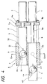
- FIG. 4 A representative type of the conventional screen changers is illustrated in Figs. 4 to 11.
- the screen changer generally indicated by 1 in Fig. 4 comprises a housing 2 in which two parallel through-holes 23 and 24 having a circular cross section as taken normal to the axis, two cylindrical slide bars 3 and 4 that are fitted into said through-holes 23 and 24, respectively, in a liquid-tight and reciprocating manner, and hydraulic cylinders 5 and 6 that are fixed to said housing 2 via a plurality of tie-bars 8, nuts 8a and a clamping plate 7 and which have piston rods 5a and 6a connected to said slide bars 3 and 4, respectively.
- said housing 2 has a through-channel 11 formed in a direction perpendicular to said through-holes 23 and 24, said through-channel 11 has an inflow channel 11a which separates into two directions part of the way and the two branches, after crossing the respective through-holes 23 and 24, meet part of the way in an outflow channel 11b.
- Each of the slide bars 3 and 4 has a channel portion and a filter portion that each communicate with said through-channel 11 and which penetrate it in a direction normal to the axis.
- Said channel and filter portions are composed of upstream compartments 31 and 41, the screen 9, a breaker plate 10 and downstream compartments 32 and 42.
- the upstream compartments 31 and 41 are formed in such a shape that openings of sufficiently large cross sections are provided to increase the effective area of filtration, or the two-dimensional area of the screen 9.
- the downstream compartments 32 and 42 are formed such that the cross sections of openings will decrease smoothly in a downward direction to insure that the large cross sections of openings just after the breaker plate 10 will match the small cross sections of openings in the outflow channel 11b.
- the through-holes 23 and 24 formed in the housing 2 have sufficient lengths to seal the channel portions of the slide bars 3 and 4, respectively, when they reciprocate.
- the first slide bar 3 is shown to be in such a state that filtration is possible, namely, the through-channel 11 in the housing 2 is in communication with the filter portion of the first slide bar 3, and the second slide bar 4 is shown to be in such a state the screen 9 can be cleaned or replaced, namely, the filter portion of the second slide bar 4 is exposed to the outside of the hosing 2.
- the screen changer 1 installed in it is first adapted to have both slide bars 3 and 4 positioned in the same manner as the first slide bar 3 is shown in Fig. 4 (i.e., they are positioned in such a state that filtration is possible) and, thereafter, a molten resin material is filtered.
- the molten material being delivered from the extruder enters the housing 2 through the inflow channel 11a and separates in two flows, which are filtered in the filter portions provided in the two slide bars 3 and 4 and thereafter meet in the outflow channel 11b to be discharged from the housing 2.
- the rejected contaminants collect on the sides of the screens 9 which face the upstream compartments 31 and 41 and the resistance to the flow of the molten material increases so much as to lower the operating efficiency of the extruder.
- it becomes necessary to reduce the flow resistance of the molten material by cleaning the screens 9 or replacing them with new ones.
- filtration is accomplished with only one of the two screens while the other screen is cleaned or replaced and, thereafter, the cleaned or substituted screen is used for filtration while the first mentioned screen is cleaned or replaced.
- the slide bar 3 or 4 in which the screen 9 is to be cleaned or replaced is pushed from the state of the first slide bar 3 (see Fig. 4) to the state of the second slide bar 4 (also see Fig. 4) by means of the hydraulic cylinder 5 or 6 and, after the screen 9 is cleaned or replaced, the slide bar is pulled back to the initial state (i.e., the state of the first slide bar 3). This procedure is successively followed for the two slide bars 3 and 4 one at a time.
- slide bars 3 and 4 When the slide bars 3 and 4 are to be pushed in the process of cleaning or replacing the screens 9, either slide bar is pushed in one action. On the other hand, when they are to be pulled back, either slide bar makes a temporary stop so that its channel and filter portions are filled with the molten material to eliminate air and only thereafter is either slide bar pulled back to the initial state (i.e., where filtration is possible).
- the reason for adopting this procedure is as follows.
- Figs. 6 and 7 shows the state where the second slide bar 4 has been pulled back to a position intermediate between the filtrable state and the cleanable or replaceable state such that the channel and filter portions of said second slide bar 4 are sealed and isolated within the through-hole 24 in the housing 2, and as shown, a material injection channel 43 which communicates the upstream compartment 41 of said filter portion to the inflow channel 11a in the housing, a first air withdrawing channel 44 which communicates the topmost part of the entrance end of the upstream compartment 41 to the outside of the housing 2, and a third air withdrawing channel 45 which communicates the topmost part of the exit end of the downstream compartment 42 of said filter portion to the outside of the housing 2 are provided axially in said intermediate position along the outer surface of the second slide bar 4.
- the first slide bar 3 is similarly provided with a material injection channel 33, a first air withdrawing channel 34 and a third air withdrawing channel 35.
- the tips of the material injection channel 33 (34), the first air withdrawing channel 34 (44) and the third air withdrawing channel 35 (45) are sealed within the through-hole 23 (24) in the housing 2 when the respective slide bar is in the filtrable state.
- the second slide bar 4 is in the intermediate position shown in Figs. 6 and 7, its channel and filter portions are emptied of air and filled with the molten material in the following manner.
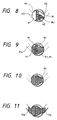
- Figs. 8 to 11 show the sequence of events that occur in that part of the screen changer which is shown in Fig. 5.
- Fig. 8 shows the state of the channel and filter portions of the second slide bar 4 before it is pulled back to the intermediate position.
- the upstream compartment 41 of the slide bar 4 is empty or filled with nothing but air a1.
- the downstream compartment 42 has a molten material m2 remaining in the lower part (which is sometimes completely absent as a result of cleaning) and has an air portion a2 present in the upper part.
- a molten material m1 flows gradually from the inflow channel 11a into the upstream compartment 41 via the material injection channel 43 (not shown) provided in an area closer to the viewer and as the upstream compartment 41 is progressively filled with the molten material m1, air a1 is pushed for displacement to the outside of the housing 2 via the first air withdrawing channel 44.
- the molten material m1 which continues to flow passes through the screen 9 and the breaker plate 10 to enter the downstream compartment 42 and as the latter is progressively filled with the molten material m1, air a2 is pushed for displacement to the outside of the housing 2 via the third air withdrawing channel 45.
- the upstream compartment 41 is completely filled with the molten material m1 and the air a2 remaining at the corners in the topmost part of the downstream compartment 42 (see Fig. 9) is pushed out of said compartment by means of the viscosity of the molten materials m1 and m2 which completely fill said downstream compartment 42.
- the upstream compartment 41 and the downstream compartment 42 are found to have been filled with the molten materials m1 and m2 by confirming that they are discharged through the tips of the first and third air withdrawing channels 44 and 45 which communicate to the outside of the housing 2.
- Fig. 10 the upstream compartment 41 is completely filled with the molten material m1 and the air a2 remaining at the corners in the topmost part of the downstream compartment 42 (see Fig. 9) is pushed out of said compartment by means of the viscosity of the molten materials m1 and m2 which completely fill said downstream compartment 42.
- the upstream compartment 41 and the downstream compartment 42 are found to have been filled with the molten materials
- the upstream and downstream compartments 41 and 42 are filled with the molten materials m1 and m2, namely, the channel and filter portions of the second slide bar 4 are completely filled with the molten material; thus, the second slide bar 4 has been pulled back to the filtrable state where the filter portion communicates with the inflow channel 11a and the outflow channel 11b in the housing 2.
- the above-described procedure allows the screens 9 to be cleaned or replaced without letting air to be entrapped in the molten material.
- the conventional screen changer has suffered from various problems as mentioned below.
- the air at the corners in the topmost part of the downstream compartment shown in Fig. 9 are not completely displaced by the pushing action of the molten material but will often remain in that downstream compartment.
- Such residual air is sensitive to the slightest change in the flow conditions of the molten material and will abruptly be discharged as part of the molten material.
- the transition from the high pressure in the extruder to a lower atmosphere occurs so rapidly that the hot and pressurized air in the molten material will burst as a result of sudden expansion, thereby causing broken strands to emerge from the die.
- a continuous strand emerging from the die is taken up by a granulator for granulation but if it breaks in the middle, the subsequent portion is discontinuous from the granulator and cannot be taken by the latter.
- the subsequent portion of the broken strand not only fails to be taken up by the granulator; broken strands will keep emerging from the die and, having nowhere to go, they will collect progressively until the normal operation of the extruder is prevented.
- the present invention has been accomplished under these circumstances and has as an object providing a screen changer that is adapted to insure that no air will be left in the channel and filter portions of either slide bar during screen cleaning or replacement.
- the screen changer of the invention comprises basically a housing having a through-channel and through-holes that cross said through-channel and columnar slide bars that each have a filter portion communicable with said through-channel and which are inserted into the through-holes in said housing in a liquid-tight and reciprocating manner, such that a molten material enters said housing via an inflow channel to the through-channel and passes through the filter portions of said slide bars to come out of said housing via an outflow channel from the through-channel, and material injection channels which communicate the upstream compartments in said filter portions to said inflow channel and first air withdrawing channels which communicate the topmost parts of the upstream compartments in said filter portions to the outside of said housing are provided along the outer surfaces of said slide bars in the position where the filter portions of said slide bars are sealed and isolated within the through-holes in said housing as a result of the movement of said slide bars.
- This screen changer is provided in that second air withdrawing channels that penetrate the topmost parts of the downstream compartments in the filter portions of said slide bars to reach the outer surfaces of said slide bars and which extend along the outer surfaces of the slide bars to communicate with the outside of said housing are provided in the position where said filter portions are sealed and isolated within the through-holes in said housing.
- the screen changer also has material withdrawing channels that are provided through said housing and that communicate the downstream compartments in the filter portions of said slide bars to the outside of said housing in the position where said filter portions are sealed and isolated within the through-holes in said housing.
- the screen changer of the invention will operate in the following manner.
- a slide bar that has been occupied with air in spaces in its channel and filter portions is pulled back to its intermediate position (i.e., where its filter portion is sealed and isolated within a through-hole in the housing)
- a molten material enters the housing via an inflow channel to the through-channel and passes through the material injection channel to flow into the upstream compartment, thereby progressively filling spaces in the channel and filter portions of the slide bar; at the same time, the air occupying those spaces is displaced by being pushed through the first and second air withdrawing channels to come out of the housing.
- first and second air withdrawing channels are provided to communicate with the topmost parts of the upstream and downstream compartments, respectively, the air occupying the channel and filter portions of slide bar will remain above the molten material being introduced into those portions and the entire part of the air can be completely pushed out of those portions.
- the molten material which has filled the channel and filter portions of the slide bar will leak out of these portions via the first and second air withdrawing channels, indicating that the air has been completely displaced from those portions.
- the screen changer of the invention ensures that the air occupying the spaces in the channel and filter portions of the slide bar is completely pushed out of the housing via the firsts and second air withdrawing channels and, in addition, the molten material containing the air bubbles will also flow out of the housing via the material withdrawing channel. Since the material withdrawing channel is provided adjacent the exit end of the downstream compartment, the entire portion of the molten material in the channel and filter portions will flow out of the housing.
- the molten material containing air bubbles can be regarded as having flowed out completely if no more air bubbles are found to exist in the molten material flowing out of the material withdrawing channel.
- Fig. 1 is a front section of the essential part of the screen changer of the invention
- Fig. 2 is a horizontal section of Fig. 1
- Fig. 3 is a section III-III of Fig. 1.
- the screen changer of the invention has generally the same construction as the conventional art apparatus shown in Fig. 4 which, therefore, is applicable to the invention.
- the screen changer generally indicated by 1 comprises a housing 2 in which two parallel through-holes 23 and 24 having a circular cross section as taken normal to the axis, two cylindrical slide bars 3 and 4 that are fitted into said through-holes 23 and 24, respectively, in a liquid-tight and reciprocating manner, and hydraulic cylinders 5 and 6 that are fixed to said housing 2 via a plurality of tie-bars 8, nuts 8a and a clamping plate 7 and which have piston rods 5a and 6a connected to said slide bars 3 and 4, respectively.
- cross sections of the through-holes 23 and 24 in the housing 2 and those of the slide bars 3 and 4 as taken normal to the axis are by no means limited to a circular shape but may be elliptical or assume rectangular and other polygonal shapes.
- the housing 2 has a through-hole 11 formed in a direction perpendicular to said through-holes 23 and 24; said through-channel 11 has an inflow channel 11a which separates into two directions part of the way and the two branches, after crossing the respective through-holes 23 and 24, meet part of the way in an outflow channel 11b.
- the slide bars 3 and 4 each have a channel and a filter portion formed therein that communicate with said through-channel 1 to penetrate it in a direction normal to the axis; the channel portion of the slide bar 3 (or 4) consists of an upstream compartment 31 (or 41) and a downstream compartment 32 (or 42), and the filter portion of each slide bar is composed of a screen 9 and a breaker plate 10.
- the upstream compartments 31 and 41 are formed in such a shape that openings of sufficiently large cross sections are provided to increase the effective area of filtration, or the two-dimensional area of the screen 9.
- the downstream compartments 32 and 42 are formed such that the cross sections of openings will decrease smoothly in a downward direction to insure that the large cross sections of openings just after the breaker plate 10 will match the small cross sections of openings in the outflow channel 11b.
- the through-holes 23 and 24 formed in the housing 2 have sufficient lengths to seal and isolate the channel and filter portions of the slide bars 3 and 4, respectively, when they reciprocate.
- the thickness of the housing 2 as measured from the through-channel 11 to its lateral side is sized to be greater than the width of the opening in the channel through each of the slide bars 3 and 4.
- the slide bar 3 (or 4) is driven by the hydraulic cylinder 5 (or 6) to move within the through-hole 23 (or 24) in the housing 2 so as to reciprocate between the two states shown in Fig. 4, one being the filtrable state assumed by the fist slide bar 3, in which the through-channel 11 in the housing 2 communicates with the filter portion of the first slide bar 3, and the other being the state assumed by the second slide bar 4 for the cleaning or replacement of screen 9, in which the channel portion of the second slide bar 4 is completely exposed to the outside of the housing 2.
- the channel portion of the slide bar 3 (or 4) is sealed and isolated within the through-hole 23 (or 24) in the housing 2.
- the slide bar 3 (or 4) is provided with a material injection channel 33 (or 43) and a first air withdrawing channel 34 (or 44) that are grooves extending axially along the outer surface of the slide bar 3 (or 4) in the intermediate position where the channel portion of the slide bar 3 (or 4) is sealed and isolated within the through-hole 23 (or 24).
- the material injection channel 33 (or 43) communicates the upstream compartment 31 (or 41) to the inflow channel 11a and the first air withdrawing channel 34 (or 44) communicates the entrance end which is the topmost part of the upstream compartment 31 (or 41) to the outside of the side wall of the housing 2.
- a second air withdrawing channel 36 which penetrates the topmost part of the downstream compartment 32 (or 42), i.e., upward from a position right after the breaker plate 10, and which then communicates to the outside of the side wall of the housing 2 is provided as a groove extending axially along the outer surface of the slider bar 3 (or 4) in the above-defined intermediate position.
- a material withdrawing channel 37 that communicates the exit end of the downstream compartment 32 (or 42) to the outside of the side wall of the housing 2 is provided through the housing 2 in the intermediate position of the slide bar 3 (or 4).
- groove-like material injection channel 33 or 43
- first air withdrawing channel 34 or 44
- second air withdrawing channel 36 or 46
- these channels may be provided on the outer surface of the slide bar 3 (or 4) or the inner surface of the through-hole 23 (or 24) in the housing 2, they are better provided on the outer surface of the slide bar 3 (or 4) as shown in Figs. 1 to 3 in order to assure ease in the manufacture of the apparatus.
- the screen changer 1 having the construction described above will operate in the following manner. First suppose that the slide bar 3 (or 4) has been pulled back to the intermediate position by means of hydraulic cylinder 5 (or 6) via piston rod 5a (or 6a) after the cleaning or replacement of screen 9.
- the openings of the upstream compartment 31 (or 41) and the downstream compartment 32 (or 42) are sealed and isolated within the through-hole 23 (or 24) between the through-channel 11 in the housing 2 and its side wall; in addition, the upstream compartment 31 (or 41) is allowed to communicate with the inflow channel 11a and the outside of the side wall of the housing 2 via the material injection channel 33 (or 43) and the first air withdrawing channel 34 (or 44), respectively; at the same time, the downstream compartment 32 (or 42) is allowed to communicate with the outside of the side wall of the housing 2 via the second air withdrawing channel 36 (or 46) and the material withdrawing channel 37 (or 47).
- the material injection channel 33 (or 43) has communicated with the inflow channel 11a, the molten material will simultaneously flow into the upstream compartment 31 (or 41) from the inflow channel 11a via the material injection channel 33 (or 43).
- the molten material which has flowed into the upstream compartment 31 (or 41) pushes the residual air out of said compartment via the first air withdrawing channel 34 (or 44), whereby the upstream compartment 31 (or 41) is progressively filled up with the molten material from bottom to top. Since the first air withdrawing channel 34 (or 44) has its terminal end provided in the topmost part of the upstream compartment 31 (or 41), the residual air can be completely pushed out of the upstream compartment 31 (or 41) and this is verified by the subsequent flowing of the molten material to emerge from the housing via the first air withdrawing channel 34 (or 44). The molten material which has flowed into the upstream compartment 31 (or 41) will then pass through the screen 9 and the breaker plate 10 to flow into the downstream compartment 32 (or 42).
- the molten material which has flowed into the downstream compartment 32 (or 42) pushes the residual air out of said compartment via the second air withdrawing channel 36 (or 46), whereby the downstream compartment 32 (or 42) is progressively filled up with the molten material from bottom to top. Since the second air withdrawing channel 36 (or 46) has its terminal end provided in the topmost part of the downstream compartment 32 (or 42), the residual air can be completely pushed out of the downstream compartment 32 (or 42) and this is verified by the subsequent flowing of the molten material to emerge from the housing via the second air withdrawing channel 36 (or 46). The molten material which has filled up the downstream compartment 32 (or 42) will flow out of the housing via the material withdrawing channel 37 (or 47).
- the molten material to be handled has a low viscosity in the range from 3000 to 1500 poises, the residual air will stay in the upper part of the space which is to be filled up with the molten material and it can be completely displaced by the provision of the first air withdrawing channels 34 and 44 and the second air withdrawing channels 36 and 46 because air bubbles are yet to be entrapped in the molten material.
- the viscosity of the molten material is lower than 1000 poises, residual air and other foreign matter will enter the molten material and the provision of the material withdrawing channels 37 and 47 becomes necessary.
- the slide bars 3 and 4 which have thus been emptied of residual air from their channel and filter portions are driven by the hydraulic cylinders 5 and 6 to be pulled back to the filtrable state.
- the screen changer of the invention offers the following advantages.
Landscapes
- Engineering & Computer Science (AREA)
- Mechanical Engineering (AREA)
- Extrusion Moulding Of Plastics Or The Like (AREA)
Applications Claiming Priority (2)
| Application Number | Priority Date | Filing Date | Title |
|---|---|---|---|
| JP6225238A JPH0890635A (ja) | 1994-09-20 | 1994-09-20 | スクリーンチェンジャ |
| JP225238/94 | 1994-09-20 |
Publications (2)
| Publication Number | Publication Date |
|---|---|
| EP0703056A2 true EP0703056A2 (fr) | 1996-03-27 |
| EP0703056A3 EP0703056A3 (fr) | 1996-10-30 |
Family
ID=16826165
Family Applications (1)
| Application Number | Title | Priority Date | Filing Date |
|---|---|---|---|
| EP95114710A Withdrawn EP0703056A3 (fr) | 1994-09-20 | 1995-09-19 | Changeur de filtre |
Country Status (3)
| Country | Link |
|---|---|
| US (1) | US5603828A (fr) |
| EP (1) | EP0703056A3 (fr) |
| JP (1) | JPH0890635A (fr) |
Cited By (1)
| Publication number | Priority date | Publication date | Assignee | Title |
|---|---|---|---|---|
| DE102007057816A1 (de) * | 2007-11-30 | 2009-06-04 | Kreyenborg Verwaltungen Und Beteiligungen Gmbh & Co. Kg | Filtrationseinrichtung |
Families Citing this family (11)
| Publication number | Priority date | Publication date | Assignee | Title |
|---|---|---|---|---|
| JP2855088B2 (ja) * | 1995-04-19 | 1999-02-10 | 株式会社日本製鋼所 | スクリーンチェンジャの瀘過方法及びスクリーンチェンジャ |
| IT1301946B1 (it) * | 1998-07-28 | 2000-07-20 | Previero Sas | Gruppo di filtrazione per materiale plastico fuso con elementifiltranti sostituibili senza arresto del flusso di materiale. |
| JP4318623B2 (ja) * | 2004-10-25 | 2009-08-26 | 株式会社神戸製鋼所 | スクリーンチェンジャ |
| JP5518784B2 (ja) * | 2011-04-13 | 2014-06-11 | 株式会社日本製鋼所 | スクリーンチェンジャのスクリーン交換方法及びスクリーンチェンジャ |
| US9090002B2 (en) * | 2011-10-06 | 2015-07-28 | Kolcor Technologies LLC | Sealing device in a polymer filtration device |
| JP5751718B2 (ja) * | 2012-10-24 | 2015-07-22 | 株式会社日本製鋼所 | スクリーンチェンジャ及びスクリーンチェンジャの予備充填方法 |
| KR200473402Y1 (ko) * | 2014-02-04 | 2014-07-01 | (주)영우케미칼 | 압출기용 스크린 체인저 |
| EP3308940B1 (fr) * | 2016-10-17 | 2025-03-05 | Next Generation Analytics GmbH | Système de filtre pour les fluides visqueux ou fortement visqueux, surtout plastique fondu et procédé de filtration des liquides visqueux ou fortement visqueux |
| US11260570B2 (en) * | 2018-05-07 | 2022-03-01 | PSI-Polymer Systems, Inc. | Filtration apparatuses and screen changer devices for polymer processing and related methods |
| KR102411216B1 (ko) * | 2021-09-03 | 2022-06-22 | 에코다이스(주) | 재생 원료 압출을 위한 다중 자동 다이스 |
| CN116638734B (zh) * | 2023-07-11 | 2025-09-30 | 湖北聚氟化工科技有限公司 | 一种聚四氟乙烯悬浮树脂挤出机 |
Family Cites Families (5)
| Publication number | Priority date | Publication date | Assignee | Title |
|---|---|---|---|---|
| US3684419A (en) * | 1971-01-25 | 1972-08-15 | Bradford R Voight | Screen changer for extruders |
| US4025434A (en) * | 1975-10-06 | 1977-05-24 | Bolton-Emerson, Inc. | Screen changer with pre-fill screen blocks |
| US3983038A (en) * | 1975-11-03 | 1976-09-28 | Heston Eugene E | Self-purging screen changer and strainer plate |
| US4814186A (en) * | 1988-02-29 | 1989-03-21 | Beringer Co., Inc. | Polymer filtration apparatus |
| DE3941831C1 (fr) * | 1989-12-19 | 1990-10-18 | Kreyenborg Verwaltungen Und Beteiligungen Kg, 4400 Muenster, De |
-
1994
- 1994-09-20 JP JP6225238A patent/JPH0890635A/ja active Pending
-
1995
- 1995-09-19 EP EP95114710A patent/EP0703056A3/fr not_active Withdrawn
- 1995-09-20 US US08/531,080 patent/US5603828A/en not_active Expired - Lifetime
Non-Patent Citations (1)
| Title |
|---|
| None |
Cited By (1)
| Publication number | Priority date | Publication date | Assignee | Title |
|---|---|---|---|---|
| DE102007057816A1 (de) * | 2007-11-30 | 2009-06-04 | Kreyenborg Verwaltungen Und Beteiligungen Gmbh & Co. Kg | Filtrationseinrichtung |
Also Published As
| Publication number | Publication date |
|---|---|
| EP0703056A3 (fr) | 1996-10-30 |
| JPH0890635A (ja) | 1996-04-09 |
| US5603828A (en) | 1997-02-18 |
Similar Documents
| Publication | Publication Date | Title |
|---|---|---|
| US5603828A (en) | Filter screen changer for resin extruder | |
| JP2855088B2 (ja) | スクリーンチェンジャの瀘過方法及びスクリーンチェンジャ | |
| US4701118A (en) | Apparatus for filtering plasticized materials in extruders | |
| DE3905963C2 (de) | Polymer-Filtervorrichtung | |
| US4167384A (en) | Filter screen exchanging apparatus for plastic extruder | |
| DE3941831C1 (fr) | ||
| EP1556202B1 (fr) | Dispositif filtrant a lavage a contre-courant pour matiere en fusion et organe de distribution pour un tel dispositif filtrant | |
| EP0617992B1 (fr) | Filtre pour la filtration de résine fondue et dispositif de filtration pour la formation de résine à plusieurs couches | |
| EP0744271A1 (fr) | Couche filtrante pour extrudeuses a resines et dispositif de remplacement d'ecrans pour extrudeuses a resines | |
| EP1082205B1 (fr) | Dispositif de filtration pour extrudeuses et machines a mouler par injection | |
| EP0680815B1 (fr) | Dispositif de filtration pour presses à extruder | |
| JPH06500278A (ja) | フィルタ交換ユニット | |
| DE19834302C2 (de) | Filtereinrichtung für Strangpressen und Spritzgießmaschinen | |
| JP4318623B2 (ja) | スクリーンチェンジャ | |
| DE19500060C1 (de) | Filtereinrichtung für Strangpreß- und Spritzgießmaschinen | |
| EP4196247B1 (fr) | Methode de netoyage des modules d'un dispositif de filtration et module de filatration | |
| WO2002016113A9 (fr) | Dispositif pour filtrer des substances liquides, corps support et procede permettant d'actionner ledit dispositif | |
| JP3641095B2 (ja) | 樹脂成形機用のスクリーン交換装置 | |
| JP2778914B2 (ja) | 樹脂成形機におけるスクリーン交換装置 | |
| JPH08252859A (ja) | スクリーンチェンジャ | |
| DE2705560A1 (de) | Filter fuer polymerschmelzen und polymerloesungen | |
| JPH01108019A (ja) | スクリーンチェンジャー | |
| EP0750979A1 (fr) | Appareil de changement de filtre | |
| EP2361662A1 (fr) | Filtre à plaques horizontales | |
| DE102004010968A1 (de) | Vorrichtung zum Filtrieren eines Fluids, insbesondere eines verflüssigten Kunststoffes |
Legal Events
| Date | Code | Title | Description |
|---|---|---|---|
| PUAI | Public reference made under article 153(3) epc to a published international application that has entered the european phase |
Free format text: ORIGINAL CODE: 0009012 |
|
| AK | Designated contracting states |
Kind code of ref document: A2 Designated state(s): FR IT |
|
| PUAL | Search report despatched |
Free format text: ORIGINAL CODE: 0009013 |
|
| AK | Designated contracting states |
Kind code of ref document: A3 Designated state(s): FR IT |
|
| STAA | Information on the status of an ep patent application or granted ep patent |
Free format text: STATUS: THE APPLICATION IS DEEMED TO BE WITHDRAWN |
|
| 18D | Application deemed to be withdrawn |
Effective date: 19970501 |