EP0703143B1 - Befestigung von einer Hilfsantriebsvorrichtung auf einer Welle - Google Patents
Befestigung von einer Hilfsantriebsvorrichtung auf einer Welle Download PDFInfo
- Publication number
- EP0703143B1 EP0703143B1 EP95305833A EP95305833A EP0703143B1 EP 0703143 B1 EP0703143 B1 EP 0703143B1 EP 95305833 A EP95305833 A EP 95305833A EP 95305833 A EP95305833 A EP 95305833A EP 0703143 B1 EP0703143 B1 EP 0703143B1
- Authority
- EP
- European Patent Office
- Prior art keywords
- propeller
- boss
- shaft
- auxiliary
- tightening
- Prior art date
- Legal status (The legal status is an assumption and is not a legal conclusion. Google has not performed a legal analysis and makes no representation as to the accuracy of the status listed.)
- Expired - Lifetime
Links
- 238000005192 partition Methods 0.000 claims abstract description 21
- 230000000295 complement effect Effects 0.000 claims description 8
- 238000006073 displacement reaction Methods 0.000 claims description 2
- 230000004048 modification Effects 0.000 description 4
- 238000012986 modification Methods 0.000 description 4
- 230000002093 peripheral effect Effects 0.000 description 4
- 238000000034 method Methods 0.000 description 2
- 230000003014 reinforcing effect Effects 0.000 description 1
Images

Classifications
-
- B—PERFORMING OPERATIONS; TRANSPORTING
- B63—SHIPS OR OTHER WATERBORNE VESSELS; RELATED EQUIPMENT
- B63H—MARINE PROPULSION OR STEERING
- B63H23/00—Transmitting power from propulsion power plant to propulsive elements
- B63H23/32—Other parts
- B63H23/34—Propeller shafts; Paddle-wheel shafts; Attachment of propellers on shafts
Definitions
- the invention relates to a propeller system.
- An object of the invention is to propose a propeller system having an auxiliary propelling device that can improve propelling performance without modification, or with minor modification, of an existing propeller shaft.
- DE-B-1293056 discloses a propeller system including a propeller shaft, a propeller including a propeller boss mounted on the shaft and a tightening nut threaded onto the shaft and maintaining the propeller boss thereon.
- US-A-4391567 also discloses a propeller system including a propeller shaft, a propeller including a propeller boss mounted on the shaft and means for maintaining the propeller boss on the shaft.
- a propeller system including a propeller shaft, a propeller including a propeller boss mounted on the shaft, a tightening nut threaded onto the shaft and maintaining the propeller boss thereon, and an auxiliary propeller device comprising:
- the invention can improve propelling performance in high speed boats or fishing boats, which requires no or little modification of the existing propeller shaft system.
- said boss member and said internal partition comprise a unitary one-piece structure of the same material.
- said internal partition has therethrough a central through-hole.
- said auxiliary tightening member comprises a bolt extending through said through-hole to be threaded into a screw hole in the end of the shaft, said bolt having a head positioned in said second interior portion and operable upon threaded tightening of said bolt to force said internal partition in said direction.
- said auxiliary tightening means comprises a nut positioned in said second interior portion and operable to be threadably tightened over an end portion of the shaft to extend through said through-hole to thereby force said internal partition in said direction.
- said boss member has an interior step portion to engage an edge of a ring to be positioned on the shaft between the propeller boss and the tightening nut.
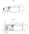
- Fig. 1 shows the assembly structure of an ordinary propeller of a double-nut type.
- the fixture of propeller boss 2 (propeller blades not shown) to propeller shaft 3 is of the ordinary double-nut type.
- screw portion will be understood to mean a threaded portion which is profiled to accept a nut or similarly threaded component in a complementary and tight relationship.
- Fig. 2 shows the assembly structure of an ordinary propeller of the double-nut type with the auxiliary propelling device A mounted thereon.
- Screw hole 32 having the same axis as the propeller shaft, is formed at end part of propeller shaft 3.
- the one or more convex parts A3 are one or more complementary concave parts 21 formed at the rear end of propeller boss 2.
- boss portion A1 of auxiliary propelling device A is fitted over and fitted with nut 5 and nut 6 at the end of propeller shaft 3.
- the convex part A3 of boss A1 of auxiliary propelling device A is engaged in a tightly complementary way with a corresponding concave part 21 of propeller boss 2.
- Assembly bolt 7 is screwed through spring washer 8 and screw hole 32 at the end of propeller shaft 3, the head 71 of bolt 7 abuts the rear end of internal partition A2, to thereby clamp internal partition A2 of auxiliary propelling device A with head 71 of assembly bolt 7.
- boss A1 of auxiliary propelling device A is fixed rigidly to propeller shaft 3.
- boss A1 of auxiliary propelling device A is fixed very firmly in the radial direction because the gap formed between the external peripheral surface of nut 5 and the inner peripheral surface of boss A1 of auxiliary propelling device A, is very small.
- This assembly structure of auxiliary propelling device and propeller boss 2 rotate in the same direction at the same rotating speed.
- the result is that the plurality of blades set in almost the same radial direction (not shown) to each of boss A1 and 2, can generate thrust efficiently.
- Fig. 3 shows propeller 1 fixed with a tightening nut to prevent loosening at the end portion.
- Propeller boss 2 (propeller blades not shown) is fixed to propeller shaft 3 as follows. Propeller boss 2 is mounted onto propeller shaft 3 by means of key 4, tightening nut 5' and ring 10. Said tightening nut 5' screwed on screw portion 31 formed at end of propeller shaft 3 in a way similar to that described above regarding the first embodiment.
- Fig. 4 shows the assembly structure of auxiliary propelling device A mounted immediately behind propeller 1.
- auxiliary propelling device A To fix the auxiliary propelling device A to propeller 1 with a tightening nut to prevent loosening as shown in Fig. 3, tightening nut 5 is fixed to shaft 3 and the front end of boss portion A1 of auxiliary propelling device A has concave part A3. Convex part A3 of boss A1 is engaged in a tightly complementary way with concave part 21 of propeller boss 2. Section part A4 of boss A1 of auxiliary propelling device A engages ring 10.
- Convex part A3 of boss A1 of auxiliary propelling device A engages in a tightly complementary way a corresponding concave part 21 of propeller boss 2.
- propeller 1 and auxiliary propelling device A will be also be fixed in the rotating direction of propeller shaft 3.
- boss A1 of auxiliary propelling device A is constructed to be effectively integral with propeller shaft 3 and also fixed with propeller shaft 3 in the radial direction due to centrifugal force.
- auxiliary propelling device A can be fixed immediately behind propeller boss 2 without restructuring the existing propeller shaft system. Thrust can be generated efficiently with a plurality of blades equipped in almost radial configuration at each boss A1 and boss 2 (not shown) by rotating same number of rotations in almost same direction between boss A1 of auxiliary propelling device A and propeller boss 2.
Landscapes
- Chemical & Material Sciences (AREA)
- Engineering & Computer Science (AREA)
- Combustion & Propulsion (AREA)
- Mechanical Engineering (AREA)
- Ocean & Marine Engineering (AREA)
- Motor Power Transmission Devices (AREA)
- Shafts, Cranks, Connecting Bars, And Related Bearings (AREA)
- Structures Of Non-Positive Displacement Pumps (AREA)
- Jib Cranes (AREA)
- Arrangement And Driving Of Transmission Devices (AREA)
- Automobile Manufacture Line, Endless Track Vehicle, Trailer (AREA)
- Replacement Of Web Rolls (AREA)
Claims (6)
- Antriebsschraubensystem, das folgendes einschließt: eine Antriebsschraubenwelle (3), eine Antriebsschraube, die eine Antriebsschraubennabe (2) einschließt, die auf der Welle (3) montiert ist, eine Klemmutter (5 oder 5'), die auf die Welle (3) geschraubt wird und die Antriebsschraubennabe (2) auf dieser hält, und eine Antriebsschrauben-Zusatzeinrichtung, die folgende Komponenten aufweist:ein zylindrisches Zusatz-Antriebsschrauben-Nabenelement (A1), dessen Inneres durch eine integrierte innere Trennwand (A2) des Nabenelementes (A1) in axial mit Zwischenraum angeordnete erste und zweite innere Abschnitte unterteilt ist, wobei das Nabenelement (A1) über der Klemmutter (5 oder 5') und einem Ende (31) der Antriebsschraubenwelle (3) angebracht wird, wobei der erste innere Abschnitt Mittel bildet, um die Klemmutter (5 oder 5') darin aufzunehmen; undein Zusatz-Spannelement (71 oder 71'), das wenigstens teilweise in dem zweiten inneren Abschnitt aufgenommen wird, wobei das Zusatz-Spannelement Mittel definiert, die mit dem Ende (31) der Welle (3) zusammenwirken, um die innere Trennwand (A2) in eine Richtung zum Drücken gegen die Klemmutter zu drücken;wobei das Nabenelement (A1) an seinem vorderen Ende wenigstens einen konvexen Abschnitt (A3) hat, der Mittel bildet, die, wenn das Zusatz-Spannelement die innere Trennwand (A2) in die genannte Richtung drückt, mit einem komplementären konkaven Abschnitt (21) der Antriebsschraubennabe (2) zusammenwirken, um das Nabenelement (A1) drehend im Verhältnis zur Antriebsschraubennabe (2) an dieser zu befestigen und eine relative Rotationsverschiebung zwischen diesen beim Drehen der Antriebsschraubenwelle (3) zu verhindern.
- Antriebsschraubensystem nach Anspruch 1, bei dem das Nabenelement (A1) und die innere Trennwand (A2) eine unitäre, aus einem Stück bestehende Struktur aus dem gleichen Material aufweisen.
- Antriebsschraubensystem nach Anspruch 1 oder Anspruch 2, bei dem durch die innere Trennwand (A2) ein zentrales Durchgangsloch führt.
- Antriebsschraubensystem nach Anspruch 3, bei dem das Zusatz-Spannelement eine Durchsteckschraube (7) umfaßt, die durch das Durchgangsloch verläuft, um in ein Schraubloch (32) in dem Ende der Welle (3) eingeschraubt zu werden, wobei die Durchsteckschraube (7) einen Kopf (71) hat, der in dem zweiten inneren Abschnitt angeordnet ist und nach dem schraubenden Anziehen der Durchsteckschraube (7) dahingehend wirksam ist. die innere Trennwand (A2) in die genannte Richtung zu drücken.
- Antriebsschraubensystem nach Anspruch 3, bei dem das Zusatz-Spannelement eine Mutter (7') aufweist, die in dem zweiten inneren Abschnitt angeordnet ist und dahingehend wirksam ist, schraubend über einem Endabschnitt (31) der Welle (3) angezogen zu werden, um durch das Durchgangsloch zu verlaufen, um dadurch die innere Trennwand (A2) in die genannte Richtung zu drücken.
- Antriebsschraubensystem nach Anspruch 5, bei dem das Nabenelement (A1) einen inneren Stufenabschnitt hat, um mit dem Rand eines Ringes (10) ineinanderzugreifen, der auf der Welle (3) zwischen dem Nabenelement (2) und der Klemmutter (5') anzuordnen ist.
Applications Claiming Priority (3)
| Application Number | Priority Date | Filing Date | Title |
|---|---|---|---|
| JP198641/94 | 1994-08-23 | ||
| JP19864194A JP3428165B2 (ja) | 1994-08-23 | 1994-08-23 | 補助推進装置の取付け構造 |
| JP19864194 | 1994-08-23 |
Publications (2)
| Publication Number | Publication Date |
|---|---|
| EP0703143A1 EP0703143A1 (de) | 1996-03-27 |
| EP0703143B1 true EP0703143B1 (de) | 2000-05-17 |
Family
ID=16394594
Family Applications (1)
| Application Number | Title | Priority Date | Filing Date |
|---|---|---|---|
| EP95305833A Expired - Lifetime EP0703143B1 (de) | 1994-08-23 | 1995-08-22 | Befestigung von einer Hilfsantriebsvorrichtung auf einer Welle |
Country Status (6)
| Country | Link |
|---|---|
| US (1) | US5611718A (de) |
| EP (1) | EP0703143B1 (de) |
| JP (1) | JP3428165B2 (de) |
| AT (1) | ATE192990T1 (de) |
| AU (1) | AU692282B2 (de) |
| DE (1) | DE69516961D1 (de) |
Families Citing this family (3)
| Publication number | Priority date | Publication date | Assignee | Title |
|---|---|---|---|---|
| USD818812S1 (en) | 2017-04-20 | 2018-05-29 | Laurence T. Schrawder | Propeller nut |
| CN110001898A (zh) * | 2019-04-25 | 2019-07-12 | 广州船舶及海洋工程设计研究院(中国船舶工业集团公司第六0五研究院) | 船舶及其螺旋桨的紧固组件 |
| CN113605522A (zh) * | 2021-08-06 | 2021-11-05 | 浙大城市学院 | 一种管道清淤机器人的搅拌动力机构 |
Family Cites Families (6)
| Publication number | Priority date | Publication date | Assignee | Title |
|---|---|---|---|---|
| US2351356A (en) * | 1943-12-24 | 1944-06-13 | Federal Mogul Corp | Propeller inhibitor |
| DE1293056B (de) * | 1963-02-18 | 1969-04-17 | P & O Res & Dev Co | Keilnutlose Verbindung eines Schiffspropellers mit der Propellerwelle |
| US3422905A (en) * | 1967-02-16 | 1969-01-21 | Ernest Muller | Indirect driven propeller |
| US3792938A (en) * | 1973-01-26 | 1974-02-19 | Production Mold Inc | Propeller nut and fairwater |
| US4391567A (en) * | 1981-05-04 | 1983-07-05 | Dominick Ciampolillo | Corrosion preventing device for a marine propeller |
| US4538962A (en) * | 1984-01-24 | 1985-09-03 | Mccain Conrad L | Marine propeller lock |
-
1994
- 1994-08-23 JP JP19864194A patent/JP3428165B2/ja not_active Expired - Lifetime
-
1995
- 1995-08-21 AU AU30172/95A patent/AU692282B2/en not_active Ceased
- 1995-08-22 DE DE69516961T patent/DE69516961D1/de not_active Expired - Lifetime
- 1995-08-22 EP EP95305833A patent/EP0703143B1/de not_active Expired - Lifetime
- 1995-08-22 AT AT95305833T patent/ATE192990T1/de not_active IP Right Cessation
- 1995-08-23 US US08/518,302 patent/US5611718A/en not_active Expired - Fee Related
Also Published As
| Publication number | Publication date |
|---|---|
| ATE192990T1 (de) | 2000-06-15 |
| US5611718A (en) | 1997-03-18 |
| JP3428165B2 (ja) | 2003-07-22 |
| AU3017295A (en) | 1996-03-07 |
| AU692282B2 (en) | 1998-06-04 |
| EP0703143A1 (de) | 1996-03-27 |
| DE69516961D1 (de) | 2000-06-21 |
| JPH0858694A (ja) | 1996-03-05 |
Similar Documents
| Publication | Publication Date | Title |
|---|---|---|
| US5845543A (en) | Bicycle crank arm parts/assembly and assembly tools | |
| US20080096446A1 (en) | Propeller for boat | |
| US6415684B1 (en) | Bicycle crank arm parts/assembly and assembly tools | |
| AU2007333477A1 (en) | Spindle with overmolded bushing | |
| US20020085914A1 (en) | Hub assembly for marine propeller | |
| US20070045079A1 (en) | Cap member for internally geared bicycle hub | |
| EP0825148A3 (de) | Kappenbaugruppe | |
| US4204806A (en) | Folding propeller | |
| US5221168A (en) | Device for fixing external part to shaft | |
| US5967751A (en) | Propeller assembly for marine engine | |
| JPH0544576Y2 (de) | ||
| US6672834B2 (en) | Removable propeller assembly incorporating breakaway elements | |
| US5611718A (en) | Auxiliary propelling device | |
| US20140072445A1 (en) | Demountable Propeller | |
| US5356236A (en) | Device for connecting two elements in rotation | |
| US4310285A (en) | Folding propeller with rubber hub | |
| JP2705776B2 (ja) | エンジン発電機のローター回り止め構造 | |
| WO2024166448A1 (ja) | 船舶用プロペラキャップ | |
| JPS63162399A (ja) | 船舶のプロペラ取付構造 | |
| NO348123B1 (en) | Propeller attachment and retention assembly | |
| JP3056279B2 (ja) | 船舶推進機におけるロワーケーシングとロワーケーシングキャップとの固定構造 | |
| JP2541283Y2 (ja) | 締付け軸力安定用ワッシャー組込みボルト | |
| JP2963409B2 (ja) | 自動車用ハンドルボス | |
| CN117526639A (zh) | 防松锁桨夹无刷电机及其制造方法 | |
| JPH0540699Y2 (de) |
Legal Events
| Date | Code | Title | Description |
|---|---|---|---|
| PUAI | Public reference made under article 153(3) epc to a published international application that has entered the european phase |
Free format text: ORIGINAL CODE: 0009012 |
|
| AK | Designated contracting states |
Kind code of ref document: A1 Designated state(s): AT BE CH DE DK ES FR GB GR IE IT LI LU MC NL PT SE |
|
| 17P | Request for examination filed |
Effective date: 19960723 |
|
| 17Q | First examination report despatched |
Effective date: 19980514 |
|
| GRAG | Despatch of communication of intention to grant |
Free format text: ORIGINAL CODE: EPIDOS AGRA |
|
| GRAG | Despatch of communication of intention to grant |
Free format text: ORIGINAL CODE: EPIDOS AGRA |
|
| GRAH | Despatch of communication of intention to grant a patent |
Free format text: ORIGINAL CODE: EPIDOS IGRA |
|
| GRAH | Despatch of communication of intention to grant a patent |
Free format text: ORIGINAL CODE: EPIDOS IGRA |
|
| GRAA | (expected) grant |
Free format text: ORIGINAL CODE: 0009210 |
|
| AK | Designated contracting states |
Kind code of ref document: B1 Designated state(s): AT BE CH DE DK ES FR GB GR IE IT LI LU MC NL PT SE |
|
| PG25 | Lapsed in a contracting state [announced via postgrant information from national office to epo] |
Ref country code: NL Free format text: LAPSE BECAUSE OF FAILURE TO SUBMIT A TRANSLATION OF THE DESCRIPTION OR TO PAY THE FEE WITHIN THE PRESCRIBED TIME-LIMIT Effective date: 20000517 Ref country code: LI Free format text: LAPSE BECAUSE OF FAILURE TO SUBMIT A TRANSLATION OF THE DESCRIPTION OR TO PAY THE FEE WITHIN THE PRESCRIBED TIME-LIMIT Effective date: 20000517 Ref country code: IT Free format text: LAPSE BECAUSE OF FAILURE TO SUBMIT A TRANSLATION OF THE DESCRIPTION OR TO PAY THE FEE WITHIN THE PRESCRIBED TIME-LIMIT;WARNING: LAPSES OF ITALIAN PATENTS WITH EFFECTIVE DATE BEFORE 2007 MAY HAVE OCCURRED AT ANY TIME BEFORE 2007. THE CORRECT EFFECTIVE DATE MAY BE DIFFERENT FROM THE ONE RECORDED. Effective date: 20000517 Ref country code: GR Free format text: LAPSE BECAUSE OF NON-PAYMENT OF DUE FEES Effective date: 20000517 Ref country code: FR Free format text: LAPSE BECAUSE OF FAILURE TO SUBMIT A TRANSLATION OF THE DESCRIPTION OR TO PAY THE FEE WITHIN THE PRESCRIBED TIME-LIMIT Effective date: 20000517 Ref country code: ES Free format text: THE PATENT HAS BEEN ANNULLED BY A DECISION OF A NATIONAL AUTHORITY Effective date: 20000517 Ref country code: CH Free format text: LAPSE BECAUSE OF FAILURE TO SUBMIT A TRANSLATION OF THE DESCRIPTION OR TO PAY THE FEE WITHIN THE PRESCRIBED TIME-LIMIT Effective date: 20000517 Ref country code: BE Free format text: LAPSE BECAUSE OF FAILURE TO SUBMIT A TRANSLATION OF THE DESCRIPTION OR TO PAY THE FEE WITHIN THE PRESCRIBED TIME-LIMIT Effective date: 20000517 Ref country code: AT Free format text: LAPSE BECAUSE OF FAILURE TO SUBMIT A TRANSLATION OF THE DESCRIPTION OR TO PAY THE FEE WITHIN THE PRESCRIBED TIME-LIMIT Effective date: 20000517 |
|
| REF | Corresponds to: |
Ref document number: 192990 Country of ref document: AT Date of ref document: 20000615 Kind code of ref document: T |
|
| REG | Reference to a national code |
Ref country code: IE Ref legal event code: FG4D Ref country code: CH Ref legal event code: EP |
|
| REF | Corresponds to: |
Ref document number: 69516961 Country of ref document: DE Date of ref document: 20000621 |
|
| PG25 | Lapsed in a contracting state [announced via postgrant information from national office to epo] |
Ref country code: SE Free format text: LAPSE BECAUSE OF FAILURE TO SUBMIT A TRANSLATION OF THE DESCRIPTION OR TO PAY THE FEE WITHIN THE PRESCRIBED TIME-LIMIT Effective date: 20000817 Ref country code: PT Free format text: LAPSE BECAUSE OF FAILURE TO SUBMIT A TRANSLATION OF THE DESCRIPTION OR TO PAY THE FEE WITHIN THE PRESCRIBED TIME-LIMIT Effective date: 20000817 Ref country code: DK Free format text: LAPSE BECAUSE OF FAILURE TO SUBMIT A TRANSLATION OF THE DESCRIPTION OR TO PAY THE FEE WITHIN THE PRESCRIBED TIME-LIMIT Effective date: 20000817 |
|
| PG25 | Lapsed in a contracting state [announced via postgrant information from national office to epo] |
Ref country code: DE Free format text: LAPSE BECAUSE OF FAILURE TO SUBMIT A TRANSLATION OF THE DESCRIPTION OR TO PAY THE FEE WITHIN THE PRESCRIBED TIME-LIMIT Effective date: 20000818 |
|
| PG25 | Lapsed in a contracting state [announced via postgrant information from national office to epo] |
Ref country code: LU Free format text: LAPSE BECAUSE OF NON-PAYMENT OF DUE FEES Effective date: 20000822 Ref country code: IE Free format text: LAPSE BECAUSE OF NON-PAYMENT OF DUE FEES Effective date: 20000822 |
|
| PG25 | Lapsed in a contracting state [announced via postgrant information from national office to epo] |
Ref country code: MC Free format text: THE PATENT HAS BEEN ANNULLED BY A DECISION OF A NATIONAL AUTHORITY Effective date: 20000831 |
|
| EN | Fr: translation not filed | ||
| NLV1 | Nl: lapsed or annulled due to failure to fulfill the requirements of art. 29p and 29m of the patents act | ||
| REG | Reference to a national code |
Ref country code: CH Ref legal event code: PL |
|
| PLBE | No opposition filed within time limit |
Free format text: ORIGINAL CODE: 0009261 |
|
| STAA | Information on the status of an ep patent application or granted ep patent |
Free format text: STATUS: NO OPPOSITION FILED WITHIN TIME LIMIT |
|
| 26N | No opposition filed | ||
| REG | Reference to a national code |
Ref country code: IE Ref legal event code: MM4A |
|
| REG | Reference to a national code |
Ref country code: GB Ref legal event code: IF02 |
|
| PGFP | Annual fee paid to national office [announced via postgrant information from national office to epo] |
Ref country code: GB Payment date: 20030820 Year of fee payment: 9 |
|
| PG25 | Lapsed in a contracting state [announced via postgrant information from national office to epo] |
Ref country code: GB Free format text: LAPSE BECAUSE OF NON-PAYMENT OF DUE FEES Effective date: 20040822 |
|
| GBPC | Gb: european patent ceased through non-payment of renewal fee |
Effective date: 20040822 |