EP0703169A1 - Anlage zur Ausschleusung von Feinstäuben oder dgl. - Google Patents
Anlage zur Ausschleusung von Feinstäuben oder dgl. Download PDFInfo
- Publication number
- EP0703169A1 EP0703169A1 EP95114451A EP95114451A EP0703169A1 EP 0703169 A1 EP0703169 A1 EP 0703169A1 EP 95114451 A EP95114451 A EP 95114451A EP 95114451 A EP95114451 A EP 95114451A EP 0703169 A1 EP0703169 A1 EP 0703169A1
- Authority
- EP
- European Patent Office
- Prior art keywords
- pressure
- fine dust
- pressure part
- control element
- low
- Prior art date
- Legal status (The legal status is an assumption and is not a legal conclusion. Google has not performed a legal analysis and makes no representation as to the accuracy of the status listed.)
- Granted
Links
- 238000009434 installation Methods 0.000 title description 2
- 239000000843 powder Substances 0.000 title 1
- 239000000428 dust Substances 0.000 claims abstract description 43
- 238000000034 method Methods 0.000 claims abstract description 18
- 239000012530 fluid Substances 0.000 claims abstract description 9
- 238000007599 discharging Methods 0.000 claims description 9
- 230000002040 relaxant effect Effects 0.000 claims description 3
- 239000000919 ceramic Substances 0.000 claims description 2
- ORQBXQOJMQIAOY-UHFFFAOYSA-N nobelium Chemical compound [No] ORQBXQOJMQIAOY-UHFFFAOYSA-N 0.000 description 8
- 238000010586 diagram Methods 0.000 description 4
- 239000008247 solid mixture Substances 0.000 description 4
- 239000003570 air Substances 0.000 description 3
- 239000000571 coke Substances 0.000 description 2
- 239000000463 material Substances 0.000 description 2
- 239000012080 ambient air Substances 0.000 description 1
- 229910010293 ceramic material Inorganic materials 0.000 description 1
- 239000003245 coal Substances 0.000 description 1
- 238000010276 construction Methods 0.000 description 1
- 230000003628 erosive effect Effects 0.000 description 1
- 238000002309 gasification Methods 0.000 description 1
- 238000012423 maintenance Methods 0.000 description 1
- 239000000203 mixture Substances 0.000 description 1
- 239000007787 solid Substances 0.000 description 1
- 229910001220 stainless steel Inorganic materials 0.000 description 1
- 239000010935 stainless steel Substances 0.000 description 1
Images


Classifications
-
- B—PERFORMING OPERATIONS; TRANSPORTING
- B65—CONVEYING; PACKING; STORING; HANDLING THIN OR FILAMENTARY MATERIAL
- B65G—TRANSPORT OR STORAGE DEVICES, e.g. CONVEYORS FOR LOADING OR TIPPING, SHOP CONVEYOR SYSTEMS OR PNEUMATIC TUBE CONVEYORS
- B65G53/00—Conveying materials in bulk through troughs, pipes or tubes by floating the materials or by flow of gas, liquid or foam
- B65G53/34—Details
- B65G53/66—Use of indicator or control devices, e.g. for controlling gas pressure, for controlling proportions of material and gas, for indicating or preventing jamming of material
Definitions
- the present invention relates to a system for discharging fine dust or the like, with a high-pressure part working under high pressure and a low-pressure part working under low pressure, a discharge device for releasing and discharging the material supplied from the high-pressure part in the transport path of the fine dust between the high-pressure part and the low-pressure part Fine dust is arranged and the discharge device has a control element with a through opening narrowing the transport path in its flow cross-section.
- Such a system belongs to the general state of the art.
- PSR K ohle u v mwandlungs out.
- coke is present as fine dust, so-called fine coke, which must be expanded to atmospheric ambient pressure via a lock system in order to then be collected in a storage container for further use.
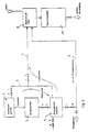
- FIG. 3 such a lock system of the general prior art is explained using a basic circuit diagram.
- a discharge device comprises a pressure vessel 3, a pressure swing vessel 5, several fittings a / b, c / d, e / f, g / h, i / k and l as well as a line system 7, which the individual components of the high pressure part of the system with each other and with a low-pressure part of the system, in particular with a low-pressure filter 9 and a storage container 11.
- the fine dust arising in a high-pressure process is collected in the pressure vessel 3 until it reaches a certain level.
- the fine dust collected in the pressure vessel 3 and under high pressure must now be discharged into the reservoir 11 under low pressure.
- the pressure change container 5 connected downstream of the pressure container 3 is first brought to the same pressure that is present in the pressure container 3. This is done by closing fittings a / b, c / d, i / k and g / h and opening fitting e / f will. Through the opening of the valve e / f, the pressure swing container 5 comes under the high pressure influence of the currently running high pressure process.
- the fittings a / b are opened and the fine dust from the pressure container 3 is emptied into the pressure change container 5.
- the gas volume displaced from the pressure swing container 5 can escape via the still open fittings e / f.
- the fittings a / b and e / f are closed and the fittings i / k are opened.
- the pressure swing container 5 is expanded to the low pressure (eg atmospheric pressure) prevailing in the low-pressure filter 9.
- the fittings i / k are closed and the fittings g / h and c / d are opened.
- the fine dust from the pressure swing container 5 enters a pneumatic transport line of the line system 7, which ends in the low-pressure filter 9.
- the valve l is opened simultaneously with the opening of the fittings c / d, so that a transport fluid, in particular transport air or a transport gas from the process, is switched on and the fine dust is pneumatically transported to the low pressure filter 9.
- the opening of the fittings g / h causes the gas volume to be replenished into the pressure change container 5 which the fine dust escaping from the pressure change container 5 has taken up.
- the fine dust is separated from the transport fluid and fed to the storage container 11. The fine dust is removed from this for further use.
- the throughput of fine dust is determined by the discontinuous process of covering and relaxing, the associated loading and relaxing times of the pressure swing container 5 and the limited container size of the pressure container 3 in an economically justifiable design.
- DE 42 25 482 and DE 42 25 483 each disclose devices for discharging solids with a throttle element.
- swirling flows occur which lead to a strong Lead to erosion on the surrounding components.
- the lifespan of these components is therefore only very short and the downtime of the system and the replacement of the components itself result in high operating costs.
- the object of the present invention is therefore to create a system for discharging fine dust or the like, with which the throughput of fine dust to be discharged can be significantly increased, largely without swirling, regardless of the size of a pressure vessel.
- control element (102) has a diffuser area (102.3) in the flow direction behind the passage opening (102.1) for the continuous expansion of the fine dust flowing through the passage opening (102.1).
- the main advantage of the plant according to the invention is that a direct, continuous disposal of the fine dust arising during a high-pressure process is possible, regardless of the amount of fine dust to be discharged. All factors that have limited the amount of fine dust to be discharged in a state-of-the-art system are eliminated.
- the pressure vessel 3 and the pressure swing vessel 5 as well as the fittings e / f, g / h, i / k and l and the corresponding part of the line system 7 are omitted without replacement.
- the flow is guided in a controlled manner through the diffuser area adjoining the through opening and the pressure is reduced in a controlled manner, and thus it is avoided that the flow swirls after passing through the through opening.
- a further advantage is that the operating costs of the plant are significantly lower than those in a plant of the prior art. Not only is the construction of the plant cheaper, but also the maintenance costs are reduced considerably, not least because the plant according to the invention is less susceptible to faults due to its simple but effective structuring.
- the transport air or the transport gas is not only switched on after the fine dust has been released, but is already switched on in the high-pressure part of the system to be transported through the discharge device fine dust so that it is on its way from high pressure part to low pressure part the system is transported pneumatically. This saves a separate transport air or gas supply system.
- the installation of a shut-off valve according to claim 3 has the advantage that the continuous discharge can be interrupted if necessary.
- FIG. 1 shows a basic circuit diagram of a system according to the invention for discharging fine dust or the like.
- fine dust is produced in a high-pressure part 100, which must be discharged to the low-pressure part 200 of the system in order to be available for further use there .
- the high-pressure part 100 is operatively connected via a line 101 to a discharge device which comprises the fittings A / B and C / D and a control element 102.
- the fittings A / B sit in line 101 in the direction of the lock in front of the control element 102 and the fittings C / D sit in line 101 in the direction of the lock behind the control element 102.
- a discharge process begins.
- the fine dust is removed directly from the high-pressure part 100 or the high-pressure process.
- a transport fluid either the normal ambient air or another transport gas, e.g. B. from the process.
- the gas / solid mixture removed from the high-pressure part 100 is pneumatically conveyed through the line 101 to the opened fittings A / B, passed through the control element 102.
- this mixture is expanded, that is, brought to the low pressure prevailing in the low-pressure part 200 of the system. It is then optionally possible to transport the expanded gas / solid mixture via a line system 201 to a low-pressure filter 202 or to discharge it directly for further use via a line system 203.
- the fine dust which has entered the low-pressure filter 202 via the line system 201 is separated from the transport fluid there and discharged via a line 205 into a predicate container 207.
- the fine dust collected in the predate container 207 can, if necessary, be removed via a valve 209 for further use.
- control element 102 is shown in longitudinal section.
- the control element 102 is preferably a ceramic expansion nozzle, such as. B. a Laval nozzle with a through opening 102.1.
- the flow cross-section of the passage opening 102.1 is calculated in such a way that the entire fine dust arising in a high-pressure process can be removed from the process together with the required amount of transport fluid.
- An inlet area 102.2 is formed in front of the passage opening 102.1, the flow cross section of which narrows inward with an entry angle ⁇ of approximately 5 ° to the passage opening 102.1 with the narrowest cross section (Q, double arrow in the illustration).
- a diffuser area 102.3 is formed behind the passage opening 102.1, the flow cross section of which extends from the inside to the outside with an exit angle ⁇ of approximately 5 ° to an exit opening 102.4.
- the diffuser area 102.1 can also be made of a non-ceramic material, such as. B. stainless steel.
- the exit angle ⁇ of the nozzle of approximately 5 ° prevents the fine dust from swirling during the relaxation. A swirling of the fine dust would lead to a removal of the nozzle material in the diffuser area 102.3.
- the length of the diffuser area 102.3 that is to say the horizontal distance between the passage opening 102.1 with the narrowest cross section Q and the outlet opening 102.4 at the end of the diffuser area 102.3, is selected such that the gas / solid mixture at the outlet opening 102.4 is just that for the pneumatic further transport required flow rate reached.
- control element 102 can be used for different fine dusts and different transport fluids.
- controls 102 can respond to different process conditions be adjusted. The calculation bases required for this are known per se to the person skilled in the art.
Landscapes
- Engineering & Computer Science (AREA)
- Mechanical Engineering (AREA)
- Air Transport Of Granular Materials (AREA)
Abstract
Description
- Die vorliegende Erfindung betrifft eine Anlage zur Ausschleusung von Feinstäuben oder dgl., mit einem unter Hochdruck arbeitenden Hochdruckteil und einem unter Niederdruck arbeitenden Niederdruckteil, wobei in dem Transportweg der Feinstäube zwischen dem Hochdruckteil und dem Niederdruckteil eine Ausschleusungseinrichtung zum Entspannen und Ausschleusen des aus dem Hochdruckteil zugeführten Feinstaubes angeordnet ist und die Ausschleusungseinrichtung ein Steuerelement mit einer den Transportweg in seinem Strömungsquerschnitt verengenden Durchgangsöfffnung aufweist.
- Eine solche Anlage gehört zu dem allgemeinen Stand der Technik. Zum Beispiel findet eine solche Anlage und ein solches Verfahren Anwendung in Kohlekraftwerken und in diesen wiederum in einer KUV-Anlage (KUV = Kohleumwandlungsverfahren). Bei einer unter Hochdruck durchgeführten Kohleteilvergasung fällt als Feinstaub vorliegender Koks, sogenannter Feinkoks, an, der über ein Schleussystem auf atmosphärischen Umgebungsdruck entspannt werden muß, um dann zur weiteren Verwendung in einem Vorratsbehälter gesammelt zu werden.
- Solche Schleussysteme sind überall dort notwendig, wo unter Hochdruck stehende Feinstäube zur weiteren Verwendung auf einen Niederdruck gebracht werden müssen.
- In Fig. 3 wird an einem Prinzipschaltbild ein solches Schleussystem des allgemeinen Standes der Technik erläutert. In einem Hochdruckteil 1 läuft ein Hochdruckprozeß ab, bei dem Feinstaub anfällt. Eine Ausschleusungseinrichtung umfaßt einen Druckbehälter 3, einen Druckwechselbehälter 5, mehrere Armaturen a/b, c/d, e/f, g/h, i/k und l sowie ein Leitungssystem 7, das die einzelnen Bauelemente des Hochdruckteils der Anlage untereinander und mit einem Niederdruckteil der Anlage, insbesondere mit einem Niederdruckfilter 9 und einem Vorratsbehälter 11, verbindet.
- Der in einem Hochdruckprozeß anfallende Feinstaub wird in dem Druckbehälter 3 gesammelt, solange bis dieser einen bestimmten Füllstand erreicht. Der in dem Druckbehälter 3 gesammelte und unter Hochdruck stehende Feinstaub muß nun in den unter Niederdruck stehenden Vorratsbehälter 11 ausgeschleust werden. Dazu wird der dem Druckbehälter 3 nachgeschaltete Druckwechselbehälter 5 zunächst auf den gleichen Druck gebracht, der in dem Druckbehälter 3 vorliegt. Dies geschieht dadurch, daß die Armaturen a/b, c/d, i/k und g/h geschlossen und die Armatur e/f geöffnet werden. Durch die Öffnung der Armatur e/f gelangt der Druckwechselbehälter 5 unter den Hochdruckeinfluß des gerade laufenden Hochdruckprozesses. Sobald der Druckwechselbehälter 5 bespannt worden ist, werden die Armaturen a/b geöffnet und der Feinstaub aus dem Druckbehälter 3 in den Druckwechselbehälter 5 entleert. Das aus dem Druckwechselbehälter 5 verdrängte Gasvolumen kann über die noch geöffneten Armaturen e/f entweichen.
- Wenn der Druckbehälter 3 entleert ist, werden die Armaturen a/b und e/f geschlossen und die Armaturen i/k geöffnet. Durch das Öffnen der Armaturen i/k wird der Druckwechselbehälter 5 auf den im Niederdruckfilter 9 herrschenden niedrigen Druck (z. B. atmosphärischen Druck) entspannt. Sobald der Druckwechselbehälter 5 vollständig entspannt ist, werden die Armaturen i/k geschlossen und die Armaturen g/h und c/d geöffnet. Durch die Öffnung der Armaturen c/d gelangt der Feinstaub aus dem Druckwechselbehälter 5 in eine pneumatische Transportleitung des Leitungssystems 7, die in dem Niederdruckfilter 9 endet. Damit der Feinstaub über die pneumatische Transportleitung in das Niederdruckfilter 9 gelangen kann, wird gleichzeitig mit der Öffnung der Armaturen c/d auch die Armatur l geöffnet, so daß ein Transportfluid, insbesondere Transportluft oder ein Transportgas aus dem Prozeß, aufgeschaltet wird und den Feinstaub pneumatisch zum Niederdruckfilter 9 transportiert. Die Öffnung der Armaturen g/h bewirkt, daß das Gasvolumen in den Druckwechselbehälter 5 nachgespeist wird, das der aus dem Druckwechselbehälter 5 auslaufende Feinstaub eingenommen hat. In dem Niederdruckfilter 9 wird der Feinstaub von dem Transportfluid getrennt und dem Vorratsbehälter 11 zugeführt. Diesem wird der Feinstaub zur weiteren Verwendung entnommen.
- Wenn der Druckwechselbehälter 5 entleert ist, werden die Armaturen c/d, g/h und l wieder geschlossen, um einen neuen Ausschleusungszyklus einzuleiten.
- In einer Anlage bzw. einem Verfahren des oben genannten Standes der Technik wird der Durchsatz an Feinstaub durch den diskontinuierlichen Vorgang des Bespannens und Entspannens, der damit verbundenen Be- und Entspannungszeiten des Druckwechselbehälters 5 und der bei wirtschaftlich vertretbarer Auslegung begrenzten Behältergröße des Druckbehälters 3 bestimmt.
- Aus DE 42 25 482 und DE 42 25 483 sind jeweils Vorrichtungen zum Ausschleusen von Feststoffen mit einem Drosselorgan bekannt. Bei diesen Vorrichtungen kommt es aufgrund einer intensiven Entspannung in dem in Strömungsrichtung hinter dem engsten Drosselquerschnitt liegenden, unkontrollierten Bereich zu verwirbelten Strömungen, die zu einer starken Erosion an den umgebenden Bauteilen führen. Die Lebensdauer dieser Bauteile ist daher nur sehr kurz und die dadurch begründeten Ausfallzeiten der Anlage wie auch der Ersatz der Bauteile selbst führen zu hohen Betriebskosten.
- Aufgabe der vorliegenden Erfindung ist daher, eine Anlage zur Ausschleusung von Feinstäuben oder dgl. zu schaffen, mit der der Durchsatz an auszuschleusendem Feinstaub unabhängig von der Größe eines Druckbehälters weitestgehend verwirbelungsfrei deutlich erhöht werden kann.
- Die Aufgabe wird dadurch gelöst, daß das Steuerelement (102) in Strömungsrichtung hinter der Durchgangsöffnung (102.1) einen Diffusorbereich (102.3) zur kontinuierlichen Entspannung des durch die Durchgangsöffnung (102.1) strömenden Feinstaubes aufweist.
- Der wesentliche Vorteil der erfindungsgemäßen Anlage liegt darin, daß eine direkte, kontinuierliche Entsorgung des während eines Hochdruckprozesses anfallenden Feinstaubes, unabhängig von der Menge des auszuschleusenden Feinstaubes möglich ist. Es entfallen alle Faktoren, die in einer Anlage des Standes der Technik zu einer Begrenzung der auszuschleusenden Feinstaubmenge geführt haben. So fallen der Druckbehälter 3 und der Druckwechselbehälter 5 sowie die Armaturen e/f, g/h, i/k und l sowie der entsprechende Teil des Leitungssystems 7 ersatzlos weg. Darüber hinaus wird die Strömung durch den sich an die Durchgangsöffnung anschließenden Diffusorbereich kontrolliert geführt und der Druck kontrolliert abgebaut und somit vermieden, daß die Strömung nach Durchtritt durch die Durchgangsöffnung verwirbelt.
- Neben dem dadurch bewirkten höheren Durchsatz, liegt ein weiterer Vorteil darin, daß die Betriebskosten der Anlage deutlich niedriger sind als die in einer Anlage des Standes der Technik. Nicht nur der Bau der Anlage wird günstiger, sondern auch die Wartungskosten werden erheblich gesenkt, nicht zuletzt deshalb, weil die erfindungsgemäße Anlage aufgrund ihrer einfachen aber wirkungsvollen Strukturierung weniger störanfällig ist.
- Mit den Unteransprüchen 2 bis 3 verbundene Vorteile werden nachstehend angeführt.
- So ist es gemäß Anspruch 2 von Vorteil, daß die Transportluft oder das Transportgas nicht erst aufgeschaltet wird, nachdem der Feinstaub entspannt worden ist, sondern bereits im Hochdruckteil der Anlage dem durch die Ausschleusungseinrichtung zu transportierenden Feinstaub aufgeschaltet wird, so daß dieser auf seinem ganzen Weg vom Hochdruckteil zum Niederdruckteil der Anlage pneumatisch transportiert wird. Dadurch wird ein separates Transportluft- oder Gaszuleitungssystem eingespart.
- Der Einbau einer Absperrarmatur gemäß Anspruch 3 hat den Vorteil, daß die kontinuierliche Ausschleusung bedarfsweise unterbrochen werden kann.
- Weitere Vorteile der vorliegenden Erfindung sind in den Unteransprüchen 4 bis 10 angeführt.
- Eine Ausführungsform der vorliegenden Erfindung wird im folgenden anhand der Zeichnungen näher beschrieben. Es zeigen:
- Fig. 1 ein Prinzipschaltbild der Anlage zur Ausschleusung von Feinstäuben oder dgl. gemäß vorliegender Erfindung;
- Fig. 2 einen Längsschnitt durch ein Steuerelement einer Ausschleusungseinrichtung der Anlage gemäß Fig. 1;
- Fig. 3 ein Prinzipschaltbild einer Anlage zur Ausschleusung von Feinstäuben oder dgl. des Standes der Technik.
- Fig. 1 zeigt ein Prinzipschaltbild einer erfindungsgemäßen Anlage zur Auschleusung von Feinstäuben oder dgl. In einem Hochdruckteil 100 einer Anlage fallen während des Hochdruckprozesses Feinstäube an, die an den Niederdruckteil 200 der Anlage abgeführt werden müssen, um dort einer weiteren Verwendung zur Verfügung stehen zu können.
- Der Hochdruckteil 100 steht über eine Leitung 101 mit einer Ausschleusungseinrichtung in Wirkverbindung, die die Armaturen A/B und C/D sowie ein Steuerelement 102 umfaßt. Die Armaturen A/B sitzen in der Leitung 101 in Schleusrichtung vor dem Steuerelement 102 und die Armaturen C/D sitzen in der Leitung 101 in Schleusrichtung hinter dem Steuerelement 102. Bei Öffnung der Armaturen A/B und C/D beginnt ein Ausschleusungsvorgang.
- Mit den Armaturen A/B und C/D in Öffnungsstellung (nicht dargestellt) wird der Feinstaub dem Hochdruckteil 100, bzw. dem Hochdruckprozeß, direkt entnommen. Gleichzeitig wird noch im Hochdruckteil 100 dem auszuschleusenden Feinstaub ein Transportfluid, entweder die normale Umgebungsluft oder ein anderes Transportgas, z. B. aus dem Prozeß, aufgeschaltet. Das dem Hochdruckteil 100 entnommene Gas-/Feststoffgemisch wird pneumatisch auf seinem Transportweg durch die Leitung 101, an den geöffneten Armaturen A/B vorbei, durch das Steuerelement 102 hindurchgeführt.
- Bei der Hindurchführung des Gas-/Feststoffgemisches durch das Steuerelement 102 wird dieses Gemisch entspannt, das heißt, auf den im Niederdruckteil 200 der Anlage herrschenden Niederdruck gebracht. Wahlweise besteht dann die Möglichkeit, das entspannte Gas-/Feststoffgemisch über ein Leitungssystem 201 zu einem Niederdruckfilter 202 zu transportieren oder über ein Leitungssystem 203 direkt zur weiteren Verwendung abzuleiten. Der über das Leitungssystem 201 in das Niederdruckfilter 202 gelangte Feinstaub wird dort von dem Transportfluid getrennt und über eine Leitung 205 in einen Vortatsbehälter 207 abgeführt. Der in dem Vortatsbehälter 207 gesammelte Feinstaub kann bedarfsweise über ein Ventil 209 zur weiteren Verwendung entnommen werden.
- In Fig. 2 ist das Steuerelement 102 im Längsschnitt dargestellt. Das Steuerelement 102 ist vorzugsweise eine keramische Entspannungsdüse, wie z. B. eine Lavaldüse, mit einer Durchgangsöffnung 102.1. Der Strömungsquerschnitt der Durchgangsöffnung 102.1 ist so berechnet, daß der gesamte, in einem Hochdruckprozeß anfallende Feinstaub zusammen mit der erforderlichen Menge Transportfluid aus dein Prozeß abgeführt werden kann. Vor der Durchgangsöffnung 102.1 ist ein Eintrittsbereich 102.2 ausgebildet, dessen Strömungsquerschnitt sich mit einem Eintrittswinkel α von ca. 5° nach innen bis zur Durchgangsöffnung 102.1 mit dem engsten Querschnitt (Q, Doppelpfeil in der Darstellung) verjüngt. Hinter der Durchgangsöffnung 102.1 ist ein Diffusorbereich 102.3 ausgebildet, dessen Strömungsquerschnitt sich mit einem Austrittswinkel β von ca. 5° von innen nach außen bis zu einer Austrittsöffnung 102.4 ausdehnt. Der Diffusorbereich 102.1 kann auch aus einem nichtkeramischen Material, wie z. B. Edelstahl gefertigt sein.
- Durch den Austrittswinkel β der Düse von ca. 5° wird verhindert, daß der Feinstaub bei der Entspannung verwirbelt. Eine Verwirbelung des Feinstaubes würde zu einer Abtragung des Düsenmaterials im Diffusorbereich 102.3 führen. Die Länge des Diffusorbereichs 102.3, das heißt, der horizontale Abstand zwischen der Durchgangsöffnung 102.1 mit dem engsten Querschnitt Q und der Austrittsöffnung 102.4 am Ende des Diffusorbereichs 102.3 ist so gewählt, daß das Gas-/Feststoffgemisch an der Austrittsöffnung 102.4 gerade die für den pneumatischen Weitertransport erforderliche Strömungsgeschwindigkeit erreicht.
- Für unterschiedliche Feinstäube und unterschiedliche Transportfluide können unterschiedliche Ausführungsformen des Steuerelements 102 eingesetzt werden. Zudem können Steuerelemente 102 an unterschiedliche Prozeßbedingungen angepaßt werden. Die dazu erforderlichen Berechnungsgrundlagen sind dem Fachmann an sich bekannt.
Claims (10)
- Anlage zur Ausschleusung von Feinstäuben oder dgl., mit einem unter Hochdruck arbeitenden Hochdruckteil und einem unter Niederdruck arbeitenden Niederdruckteil, wobei in dem Transportweg der Feinstäube zwischen dem Hochdruckteil und dem Niederdruckteil eine Ausschleusungseinrichtung zum Entspannen und Ausschleusen des aus dem Hochdruckteil zugeführten Feinstaubes angeordnet ist und die Ausschleusungseinrichtung ein Steuerelement mit einer den Transportweg in seinem Strömungsquerschnitt verengende Durchgangsöffnung aufweist
dadurch gekennzeichnet,
daß das Steuerelement (102) in Strömungsrichtung hinter der Durchgangsöffnung (102.1) einen Diffusorbereich (102.3) zur kontinuierlichen Entspannung des durch die Durchgangsöffnung (102.1) strömenden Feinstaubes aufweist. - Anlage nach Anspruch 1,
dadurch gekennzeichnet,
daß der Transport des Feinstaubes zwischen Hochdruckteil (100) und Niederdruckteil (200) mit einem Transportfluid pneumatisch erfolgt. - Anlage nach Anspruche 1 oder 2,
dadurch gekennzeichnet,
daß die Ausschleusungseinrichtung (102, A/B, C/D) eine Absperrvorrichtung (A/B, C/D) für den Transportweg umfaßt. - Anlage nach Anspruch 3,
dadurch gekennzeichnet,
daß die Absperrvorrichtung (A/B, C/D) eine Absperrarmatur (A/B) aufweist, die zwischen dem Hochdruckteil (100) und dem Steuerelement (102) angeordnet ist. - Anlage nach Anspruch 3 oder 4,
dadurch gekennzeichnet,
daß die Absperrvorrichtung (A/B, C/D) eine Absperrarmatur (C/D) aufweist, die zwischen dem Steuerelement (102) und dem Niederdruckteil (200) angeordnet ist. - Anlage nach einem der vorstehenden Ansprüche,
dadurch gekennzeichnet,
daß das Steuerelement (102) eine an die aus dem Prozeß pneumatisch abzuführende Menge Feinstaub angepaßte Entspannungsdüse ist. - Anlage nach einem der vorstehenden Ansprüche,
dadurch gekennzeichnet,
daß das Steuerelement (102) vor der Durchgangsöffnung (102.1) einen Eintrittsbereich (102.2) mit einem Neigungswinkel α von ca. 5° aufweist. - Anlage nach einem der vorstehenden Ansprüche
dadurch gekennzeichnet,
daß der Diffusorbereich (102.3) einen Neigungswinkel β von ca. 5° aufweist. - Anlage nach einem der vorstehenden Ansprüche,
dadurch gekennzeichnet,
daß das Steuerelement (102) keramisch ausgebildet ist. - Anlage nach einem der Ansprüche 2-9,
dadurch gekennzeichnet,
daß das Transportfluid ein aus dem Hochdruckteil (100) abgezweigtes Prozeßgas ist.
Applications Claiming Priority (2)
| Application Number | Priority Date | Filing Date | Title |
|---|---|---|---|
| DE4432994 | 1994-09-16 | ||
| DE19944432994 DE4432994C2 (de) | 1994-09-16 | 1994-09-16 | Anlage zur Ausschleusung von Feinstäuben |
Publications (2)
| Publication Number | Publication Date |
|---|---|
| EP0703169A1 true EP0703169A1 (de) | 1996-03-27 |
| EP0703169B1 EP0703169B1 (de) | 2001-08-22 |
Family
ID=6528370
Family Applications (1)
| Application Number | Title | Priority Date | Filing Date |
|---|---|---|---|
| EP95114451A Expired - Lifetime EP0703169B1 (de) | 1994-09-16 | 1995-09-14 | Anlage zur Ausschleusung von Feinstäuben oder dgl. |
Country Status (2)
| Country | Link |
|---|---|
| EP (1) | EP0703169B1 (de) |
| DE (1) | DE4432994C2 (de) |
Citations (3)
| Publication number | Priority date | Publication date | Assignee | Title |
|---|---|---|---|---|
| EP0366104A2 (de) * | 1988-10-26 | 1990-05-02 | Richard Kisilowski | Fördervorrichtung in Form eines Sendegerätes für staubförmige oder feinkörnige Güter |
| DE4225483A1 (de) | 1992-08-01 | 1994-02-03 | Kretschmer Horst Dr Ing | Schüttgutdrosselvorrichtung zum Entspannen, Ausschleusen, Dosieren, Dispergieren und Fördern feinkörniger Schüttgüter |
| DE4225482A1 (de) | 1992-08-01 | 1994-02-03 | Babcock Energie Umwelt | Verfahren und Vorrichtung zum Ausschleusen von Feststoffen |
Family Cites Families (5)
| Publication number | Priority date | Publication date | Assignee | Title |
|---|---|---|---|---|
| DE2628236C3 (de) * | 1976-06-24 | 1979-02-01 | Claudius Peters Ag, 2000 Hamburg | Verfahren und Vorrichtung zum Entlüften eines Druckgefäßförderers |
| DE2938369A1 (de) * | 1979-09-22 | 1981-04-16 | Dr. C. Otto & Comp. Gmbh, 4630 Bochum | Verfahren zum pneumatischen foerdern feinkoernigen brennstoffes zu einem vergaser |
| DE3331414A1 (de) * | 1983-08-31 | 1985-03-14 | Ludger 4354 Datteln Schumacher | Verfahren zur einbringung koerniger und/oder staubfoermiger gueter in pneumatische foerderanlagen und foerdervorrichtung zur durchfuehrung dieses verfahrens |
| DE3708462A1 (de) * | 1987-03-16 | 1988-09-29 | Gema Ransburg Ag | Pneumatische foerdereinrichtung |
| DE4134652C2 (de) * | 1991-10-19 | 1994-07-14 | Berchem & Schaberg Gmbh | Vorrichtung zur Druck- und Mengenstromsteuerung eines in einem Strömungskanal strömenden kompressiblen oder inkompressiblen Mediums |
-
1994
- 1994-09-16 DE DE19944432994 patent/DE4432994C2/de not_active Expired - Fee Related
-
1995
- 1995-09-14 EP EP95114451A patent/EP0703169B1/de not_active Expired - Lifetime
Patent Citations (3)
| Publication number | Priority date | Publication date | Assignee | Title |
|---|---|---|---|---|
| EP0366104A2 (de) * | 1988-10-26 | 1990-05-02 | Richard Kisilowski | Fördervorrichtung in Form eines Sendegerätes für staubförmige oder feinkörnige Güter |
| DE4225483A1 (de) | 1992-08-01 | 1994-02-03 | Kretschmer Horst Dr Ing | Schüttgutdrosselvorrichtung zum Entspannen, Ausschleusen, Dosieren, Dispergieren und Fördern feinkörniger Schüttgüter |
| DE4225482A1 (de) | 1992-08-01 | 1994-02-03 | Babcock Energie Umwelt | Verfahren und Vorrichtung zum Ausschleusen von Feststoffen |
Also Published As
| Publication number | Publication date |
|---|---|
| DE4432994A1 (de) | 1995-03-30 |
| EP0703169B1 (de) | 2001-08-22 |
| DE4432994C2 (de) | 2003-01-30 |
Similar Documents
| Publication | Publication Date | Title |
|---|---|---|
| EP0176627B1 (de) | Verfahren und Einrichtung zum pneumatischen und hydraulischen Transport von Feststoffen durch Rohrleitungen | |
| EP1404434B2 (de) | Verfahren und vorrichtung zur abreinigung von filtern für staubbelastete abgase | |
| EP1024878B1 (de) | Verfahren und vorrichtung zum reinigen eines staubabscheiders | |
| WO2011069588A1 (de) | Vorrichtung zur einspeisung eines fluids in eine feststoffförderleitung | |
| DE3637370C1 (de) | Verfahren zum Einspeisen von in einer Kavernenspeicheranlage gespeichertem Gas in ein Verbrauchernetz sowie Anordnung zum Durchfuehren eines solchen Verfahrens | |
| WO2015158429A1 (de) | Ausblaseinrichtung für eine zellenradschleuse | |
| EP1108822B1 (de) | Abwasserhebeanlage | |
| EP0603601B1 (de) | Vorrichtung zum pneumatischen Fördern von Schüttgut | |
| DD141240A3 (de) | Behaelterschleuse zur ueberfuehrung staubhaltiger und staubfoermiger gueter in ein system hoeheren druckes | |
| DE3223406A1 (de) | Blasvorrichtung zum beseitigen von aufstauungen in lagersilos fuer schuettgut | |
| DE4334699C1 (de) | Filternder Abscheider | |
| DE3323739A1 (de) | Vorrichtung zur pfropfenfoerderung von schuettgut | |
| DE3412930C2 (de) | ||
| EP0703169B1 (de) | Anlage zur Ausschleusung von Feinstäuben oder dgl. | |
| DE2248859B2 (de) | Verfahren und Vorrichtung zum pneumatischen Fördern von staubförmigem oder körnigem Schüttgut | |
| DE2363505A1 (de) | Aufgabevorrichtung einer druckluftfoerderanlage fuer schuettgut | |
| DE2058395A1 (de) | Siebvorrichtung zum Abscheiden von Feststoffen aus Fluessigkeitsstroemen in Rohrleitungen | |
| DE2219199B2 (de) | Pneumatische foerderanlage, insbesondere fuer die pfropfenfoermige foerderung von schuettguetern | |
| DE3245374C1 (de) | Verfahren und Einrichtung zum Druckreduzieren von Gichtgasen einer oberen Druckstufe | |
| EP0816266B1 (de) | Verfahren und Vorrichtung zum Befüllen einer Dichtstrom-Förderleitung | |
| DE10349871B4 (de) | Verfahren und Einrichtung zur Versorgung von mehreren pneumatischen Förder-Anlagen mit Fördergas unter Druck | |
| CH678820A5 (de) | ||
| DE102010054698A1 (de) | Vorrichtung zur Austragung von Schüttgut | |
| DE19732985C2 (de) | Verfahren zum Befüllen einer Dichtstrom-Förderleitung | |
| DE2818729B2 (de) | Rückspülbare Schnellfilteranlage |
Legal Events
| Date | Code | Title | Description |
|---|---|---|---|
| PUAI | Public reference made under article 153(3) epc to a published international application that has entered the european phase |
Free format text: ORIGINAL CODE: 0009012 |
|
| AK | Designated contracting states |
Kind code of ref document: A1 Designated state(s): BE ES FR GB IT NL |
|
| 17P | Request for examination filed |
Effective date: 19960925 |
|
| 17Q | First examination report despatched |
Effective date: 19970709 |
|
| GRAG | Despatch of communication of intention to grant |
Free format text: ORIGINAL CODE: EPIDOS AGRA |
|
| GRAG | Despatch of communication of intention to grant |
Free format text: ORIGINAL CODE: EPIDOS AGRA |
|
| GRAH | Despatch of communication of intention to grant a patent |
Free format text: ORIGINAL CODE: EPIDOS IGRA |
|
| GRAH | Despatch of communication of intention to grant a patent |
Free format text: ORIGINAL CODE: EPIDOS IGRA |
|
| GRAA | (expected) grant |
Free format text: ORIGINAL CODE: 0009210 |
|
| AK | Designated contracting states |
Kind code of ref document: B1 Designated state(s): BE ES FR GB IT NL |
|
| PG25 | Lapsed in a contracting state [announced via postgrant information from national office to epo] |
Ref country code: IT Free format text: LAPSE BECAUSE OF FAILURE TO SUBMIT A TRANSLATION OF THE DESCRIPTION OR TO PAY THE FEE WITHIN THE PRESCRIBED TIME-LIMIT;WARNING: LAPSES OF ITALIAN PATENTS WITH EFFECTIVE DATE BEFORE 2007 MAY HAVE OCCURRED AT ANY TIME BEFORE 2007. THE CORRECT EFFECTIVE DATE MAY BE DIFFERENT FROM THE ONE RECORDED. Effective date: 20010822 |
|
| GBT | Gb: translation of ep patent filed (gb section 77(6)(a)/1977) |
Effective date: 20011117 |
|
| REG | Reference to a national code |
Ref country code: GB Ref legal event code: IF02 |
|
| EN | Fr: translation not filed | ||
| PG25 | Lapsed in a contracting state [announced via postgrant information from national office to epo] |
Ref country code: ES Free format text: LAPSE BECAUSE OF FAILURE TO SUBMIT A TRANSLATION OF THE DESCRIPTION OR TO PAY THE FEE WITHIN THE PRESCRIBED TIME-LIMIT Effective date: 20020228 |
|
| PLBE | No opposition filed within time limit |
Free format text: ORIGINAL CODE: 0009261 |
|
| STAA | Information on the status of an ep patent application or granted ep patent |
Free format text: STATUS: NO OPPOSITION FILED WITHIN TIME LIMIT |
|
| 26N | No opposition filed | ||
| PGFP | Annual fee paid to national office [announced via postgrant information from national office to epo] |
Ref country code: NL Payment date: 20020924 Year of fee payment: 8 |
|
| PGFP | Annual fee paid to national office [announced via postgrant information from national office to epo] |
Ref country code: BE Payment date: 20030127 Year of fee payment: 8 |
|
| PGFP | Annual fee paid to national office [announced via postgrant information from national office to epo] |
Ref country code: GB Payment date: 20030901 Year of fee payment: 9 |
|
| PG25 | Lapsed in a contracting state [announced via postgrant information from national office to epo] |
Ref country code: BE Free format text: LAPSE BECAUSE OF NON-PAYMENT OF DUE FEES Effective date: 20030930 |
|
| BERE | Be: lapsed |
Owner name: *KRISCHIK GERD Effective date: 20030930 |
|
| PG25 | Lapsed in a contracting state [announced via postgrant information from national office to epo] |
Ref country code: NL Free format text: LAPSE BECAUSE OF NON-PAYMENT OF DUE FEES Effective date: 20040401 |
|
| NLV4 | Nl: lapsed or anulled due to non-payment of the annual fee |
Effective date: 20040401 |
|
| PG25 | Lapsed in a contracting state [announced via postgrant information from national office to epo] |
Ref country code: GB Free format text: LAPSE BECAUSE OF NON-PAYMENT OF DUE FEES Effective date: 20040914 |
|
| ET | Fr: translation filed | ||
| REG | Reference to a national code |
Ref country code: FR Ref legal event code: ERR Free format text: BOPI DE PUBLICATION N: 02/03 PAGES: 281 PARTIE DU BULLETIN CONCERNEE: BREVETS EUROPEENS DONT LA TRADUCTION N'A PAS ETE REMISE A I'INPI IL Y A LIEU DE SUPPRIMER: LA MENTION DE LA NON REMISE. LA REMISE DE LA TRADUCTION EST PUBLIEE DANS LE PRESENT BOPI. |
|
| GBPC | Gb: european patent ceased through non-payment of renewal fee |
Effective date: 20040914 |
|
| PG25 | Lapsed in a contracting state [announced via postgrant information from national office to epo] |
Ref country code: FR Free format text: LAPSE BECAUSE OF NON-PAYMENT OF DUE FEES Effective date: 20050531 |
|
| REG | Reference to a national code |
Ref country code: FR Ref legal event code: ST |
|
| PG25 | Lapsed in a contracting state [announced via postgrant information from national office to epo] |
Ref country code: FR Free format text: LAPSE BECAUSE OF NON-PAYMENT OF DUE FEES Effective date: 20010930 |