EP0703178B1 - Dispositif de va-et-vient pour un pot plat pendant son remplissage à une machine textile délivrant des mèches - Google Patents
Dispositif de va-et-vient pour un pot plat pendant son remplissage à une machine textile délivrant des mèches Download PDFInfo
- Publication number
- EP0703178B1 EP0703178B1 EP95118583A EP95118583A EP0703178B1 EP 0703178 B1 EP0703178 B1 EP 0703178B1 EP 95118583 A EP95118583 A EP 95118583A EP 95118583 A EP95118583 A EP 95118583A EP 0703178 B1 EP0703178 B1 EP 0703178B1
- Authority
- EP
- European Patent Office
- Prior art keywords
- flat
- traversing
- axis
- sliver
- swivel
- Prior art date
- Legal status (The legal status is an assumption and is not a legal conclusion. Google has not performed a legal analysis and makes no representation as to the accuracy of the status listed.)
- Expired - Lifetime
Links
Images








Classifications
-
- B—PERFORMING OPERATIONS; TRANSPORTING
- B65—CONVEYING; PACKING; STORING; HANDLING THIN OR FILAMENTARY MATERIAL
- B65H—HANDLING THIN OR FILAMENTARY MATERIAL, e.g. SHEETS, WEBS, CABLES
- B65H54/00—Winding, coiling, or depositing filamentary material
- B65H54/76—Depositing materials in cans or receptacles
- B65H54/78—Apparatus in which the depositing device or the receptacle is reciprocated
-
- B—PERFORMING OPERATIONS; TRANSPORTING
- B65—CONVEYING; PACKING; STORING; HANDLING THIN OR FILAMENTARY MATERIAL
- B65H—HANDLING THIN OR FILAMENTARY MATERIAL, e.g. SHEETS, WEBS, CABLES
- B65H2701/00—Handled material; Storage means
- B65H2701/30—Handled filamentary material
- B65H2701/31—Textiles threads or artificial strands of filaments
Definitions
- the invention relates to filling the flat can with sliver by a textile machine delivering a sliver, such as a card or stretch, the flat can under one stationary rotating turntable is moved.
- the can movement has an influence on the quality of the sliver and on the degree of can filling.
- flat cans are filled by a The flat jug rotates stationary as a delivery device is moved back and forth under this turntable, i.e. the Flat can is changed.
- the back and forth movements of the flat can take place at a constant speed up to the turning point. During this movement, the flat can takes with it Footprint in a flat position.
- EP 457 099, column 4, lines 26-33 In order to achieve a higher degree of can filling with a defined quality of the sliver to be laid down, it was proposed in the prior art (cf. EP 457 099, column 4, lines 26-33) to combine the straight-line traversing movement with a lateral movement of the flat can to this end .
- EP 457 099, column 12, 35.-39. Line assumes that the lateral, translational transverse displacement of the flat can can result in an increase in the degree of filling by shifting the loop storage of the sliver. This fact is important because the can also serves as a buffer store between the draw frame and the rotor spinning machine, reducing the number of times it is transported as the degree of filling increases.
- EP 457 099, column 4, 26.-31 In order to achieve a higher degree of can filling with a defined quality of the sliver to be laid down, it was proposed in the prior art (cf. EP 457 099, column 4, lines 26-3
- the object of the invention is to fill a flat can necessary movements of the flat can compared to their effort noticeably reduce the state of the art.
- a textile machine delivering sliver can be a card or be a stretch.
- the delivery device is a stationary one Turntable, which due to its rotation the sliver deposited cycloid-like in the flat can.
- the invention Device for traversing a flat can during the filling process on a textile machine delivering sliver is through the characterizing features of claim 1 realized.
- the reversal path of the traversing is part of the traversing path.
- the traversing path for the flat can is the distance between two reversal points.
- the flat can moves on you Reversal point too, is in the immediate vicinity before the reversal point the flat can is braked and immediately after passing through the Reversal point accelerated for a short distance. These distances braking and accelerating in the immediate vicinity the reversal point are called the reversal path.
- the movement the flat can between the two reversal paths is essentially one uniform movement.
- the flat can is in the reverse path defined from one side to the other by one fixed axis pivoted.
- the flat can is turned around pivoted such an angular amount that the upper edge of the can, which is formed by the can bulge, is laterally offset.
- This offset of the upper edge of the can is essential for the process, because takes place in the area of this upper edge of the can always the storage of the sliver.
- the counter space that is formed between the upper edge of the can, by the Swivel shifted sideways. This makes it possible for the Tape storage by the turntable laterally offset to the original Position (basic position) of the flat can can.
- This lateral offset is adjustable and corresponds approximately the thickness of the sliver to be processed.
- the angle of the swivel taken by the flat can towards their basic position is when the opposite one reaches Reverse path reversed from the basic position.
- the flat can swings in the other direction and around the axis is in this swiveled position again to the opposite Reverse path changes.
- An advantage of the invention is that the pivoting movement as a lateral transverse displacement of the flat can from the technical point of view Effort is less expensive than the known translational Transverse displacement. The effort was noticeably reduced become. Another advantage is that the inertial forces that disadvantageously when reversing the traversing device the filling process act, also compensated much cheaper become.
- the angular amount by which the flat can can be swiveled Usually the flat can is an equal amount after the swung one and the other side. This angular amount is variable and adjustable. This is useful when changing the Sliver material due to change of lot.
- Another advantage is possible influences on the sliver storage, which results from the Interaction between the direction of deposition of the sliver and the Direction of movement of the elongated side wall result, too influence. It is an added advantage that uneven angles can be adjusted for swiveling, i.e. the angular amount pivoting to one side is unequal to the angular amount of panning to the other side. In order to it becomes possible to see deviations from the centrality between flat jug and balance turntable.
- the traversing device equipped with a swivel device.
- the swivel device has a swivel encoder and a tool Axis around which the flat can is pivoted.
- the swivel encoders are arranged on both sides of the traversing path of a flat can. In with respect to the flat can, the arrangement is such that the Swivel encoder on both sides near the longitudinal walls of a flat jug are arranged.
- One swivel encoder can be used in one Position to the longitudinal wall, which is between upper can rim and adjacent gripper plate of the traversing device or lower can rim and adjacent gripper plate can be located.
- the arrangement of the rotary encoder for the longitudinal wall the flat can can also depend on the selection of the Swivel axis.
- the swivel encoders enable swiveling around an axis Swivel axis.
- the swivel encoders give the power to swivel and the direction of force on the flat can.
- the swivel encoders can advantageously arranged to each other in a horizontal plane be.
- the swivel encoders give the flat can when moving a tour at the same time. Reaches the flat can while traversing a reversal point of their traversing path, then both swivel Swiveling the flat can into a defined angle defined direction. In this position the flat jug held and led back to the other reversal point when traversing. When the other turning point is reached, they pivot The flat pot can be swiveled into the opposite angular position. This process is repeated until the jug is full and on Can change is displayed.
- the flat can hang through in a traversing device the swivel device can be swiveled.
- the flat can can however also on a transport track that supports the traversing, be swiveled or flat jug and associated transport track are swiveled together.
- a swivel encoder this is designed as an eccentrically mounted roller.
- the role is rotatably supported in its eccentric axis of rotation.
- the axis of rotation can be swiveled and fixed infinitely.
- the flat jug will between the two eccentrically mounted rollers.
- the Rolls can be arranged in the lower or upper can area be.
- Training the swivel encoder as eccentrically mounted rollers is special advantageous because a very low construction effort for Panning exists.
- the roles also become an advantageous one Guide to the flat can reached during traversing.
- An adjustment device controls depending on the reversal points the movement of the two roles.
- swivel encoder is a Sliding bar.
- the two sides near the longitudinal wall of the flat can arranged slide bars are independent of each other manageable, yet synchronizable in their interaction.
- Angle of panning is via the control of the pan encoder adjustable.
- the swivel encoders also allow the flat can to be centered in a basic position, which is advantageous for changing the can and an exact guidance of the flat jug during traversing in the panned position.
- a flat can is under the Turntable of a route.
- the turntable is stationary in the machine table arranged. It has a guide channel through which the sliver leaves the turntable and is placed in the flat can becomes. Since the flat can under the entire length When the turntable is changed, the sliver becomes cycloid-shaped and stored in individual layers in the flat can.
- the flat jug has an essentially elongated shape, i.e. the side walls are much larger than the end walls.
- FIG 1 shows one of the commonly used flat cans.
- the outer shape of the flat can is essentially formed through the two elongated side walls 2 and 3 and the two end faces 4 and 5.
- the walls 2, 3, 4 and 5 are perpendicular to their footprint 7.
- the footprint 7 of the flat can lies in the base area 6, which represents the flat floor.
- the walls 2, 3, 4, 5 are delimited from the base area 6 through the can bead 8.
- the upper limit of the flat can is through the can bulge 9. Between the can bulge 9 as upper limit of the can walls results in an area that in Figure 1 as a storage surface 10 parallel to the base 7 and is thus also arranged parallel to the base 6. How later as will be explained, the position of the storage surface 10 changes when swiveling.
- This state of the flat can 1 according to Figure 1 is referred to as the home position G.
- the basic position G is for one Can change advantageous.
- the can plate 11 is empty the flat can 1 a few centimeters below the upper can bulge 9 positioned.
- the can plate 11 is made by a pantograph as well as ring springs pressed into this position. For reasons This well-known mechanism for the Can plate not shown. With increasing weight of the sliver storage the can plate 11 in the direction of the footprint 7 pressed.
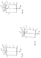
- FIG. 2 illustrates the pivoting of the flat can.
- Figure 2 shows the end face of a flat can. To see is the end face 5, which is delimited by the side faces 2 and 3 and partly through the upper can 9 and the lower Jug bead 8.
- the flat jug 1 stands with its footprint 7 on the base area 6.
- FIG. 2 facilitates understanding for a basic position G of the flat can to be defined.
- a flat jug is also in the basic position when the standing area 7 is arranged above and parallel to the base 6.
- FIG. 2 also shows a perpendicular M, which is shown in the middle between the side walls 2 and 3, to these runs parallel and is perpendicular to the base 7.
- the axis A0 around which the can 1 is to be pivoted is a longitudinal axis which perpendicular to the perpendicular M, but below that Stand area 7.
- This state according to FIG. 2 is the basic position G of the flat can 1.
- the start of the filling process for example 2a assumed that the flat can in the reverse path starts. It becomes one within this reversal path Angle ⁇ pivoted to the left about the axis A0.
- Angle ⁇ pivoted to the left about the axis A0.
- the upper edge of the can, which is formed by the bead 9 is laterally offset. This lateral offset of the top Jug rim is essential because it leads to a side Offset of the shelf 10. Due to the variability and adjustability the angle ⁇ and ⁇ can lay the sliver can be varied compared to the side of the can.
- the flat can is held in this pivoted posture according to FIG. 2a and oscillates up to the opposite reversal path.
- the flat can 1 is pivoted in the opposite direction with respect to the perpendicular L.
- Figure 2b shows this state.
- the flat can 1 with a perpendicular M was pivoted back by the amount ⁇ and moreover pivoted in the opposite direction by the angle ⁇ .
- the flat can is held in this pivoted position (FIG. 2b) and oscillates when the reversal path is left.
- the flat can is changed in the swiveled position. This corresponds to a lateral displacement of the top edge of the flat can relative to the traversing direction. With the lateral displacement of the flat can by pivoting it is achieved that the slings can be stored offset from the layer of slings already directly below.
- the flat can is advantageously pivoted by an angle which corresponds to the displacement of the flat can by approximately the thickness of a sliver to be processed. It has been found that this angle between perpendicular M and perpendicular L can be in the range of about 2 °.
- the swiveling of the flat can to one side and later to the other side can take place at the same angular amount, ie the angles ⁇ and ⁇ are equal in amount, but opposite in the direction with respect to the perpendicular L.
- the angular amount is variable and adjustable.
- the upper can rim 500 of a flat can is shown schematically.
- a turntable 600 is assigned.
- the flat can has a traversing speed with the direction of movement K.
- Der Turntable 600 has a rotation speed and a direction of rotation DR, rotational forces occurring on the circumference R1, R2 influence the sliver to be laid down. The influencing takes place also due to the flat can movement. That from the turntable 600 in the Flat jug with top jug rim receives 500 sliver a relative speed.
- the 500 act near the wall Speed components of the turntable and the flat can in opposite direction.
- the result is a lower relative speed of the sliver in this area.
- the storage radius for the sliver becomes larger, i.e. the sliver becomes slight put down more to the edge of the can.
- This effect can be due to the variability and adjustability of the angle for swiveling the flat can, i.e. the angle to be swiveled can be slightly lower be as originally without considering the described effect, provided the can rim 500 is at this point the sliver, which drifts outwards, is pivoted in an accommodating manner.
- the can rim is therefore not in the position as originally 500 ', but provided an "accommodating" Direction of pivoting RS only to the position of the upper one Can rim 500 '' swiveled, i.e. is the set angle slightly smaller than the originally intended angle of pivoting.
- An analogous situation applies to the return movement of the Flat jug.
- a relative speed of the sliver is also possible which causes the sliver to have a higher relative speed receives.
- the sliver put something away from the wall. You can do this compensate for by a larger than originally intended Angle of pivoting the top of the can 500 set becomes.
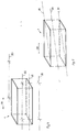
- Figures 3 and 3a show that by moving the flat can Swiveling effect achievable with the tape storage. This effect is the basis for the fact that the degree of filling is significantly opposite Pots that are not moved laterally increased can be.
- Figure 3 shows schematically some superimposed sliver loops in a traversal without lateral lateral shift the flat can. It can be seen that the sliver on the elongated side walls 2, 3 arranged one above the other is. In contrast, Figure 3a shows the state of the sliver for traversing with transverse shift. It can be seen that this Sliver to the one below or immediately above Sliver is laterally offset. The offset corresponds approximately the thickness of a sliver. With this type of storage, the Degree of filling of the flat can depending on the fiber material can be increased by up to 30%.
- the position of the axis has to be the flat can is swung, great importance.
- Figure 4 are some options for the position of the pivot axis are shown schematically.
- the axis A2 is centrally symmetrical.
- Another embodiment is the axis A1 lying underneath, which in the footprint of the flat jug. Even deeper and therefore outside the swivel axis is the A0. This case is already shown in Figure 2.
- the flat With the A3 axis the possibility becomes demonstrated that the flat can also pivoted about an axis that can be outside the flat jug and nearby one side wall.
- the axis can also be in a position that is not leads parallel to the traversing direction CR.
- Figure 5 shows the situation the A4 axis.
- This axis A4 is in the footprint 7 of the Flat jug 1 from one corner to the diagonally opposite one Corner of the flat jug.
- This position of the A4 axis is advantageous because inertia can be used cheaply can.
- Figure 6 shows the possibility of the axis for pivoting the flat can also to be able to run vertically.
- the axis A7 is vertical arranged central axis around which the flat can is pivoted can be. As the position of axis A8 shows, it can be vertical guided axis but also outside the flat can, more advantageous Way near the end wall. A swing around one of the axes shown also results in an offset of the sliver during the filing.
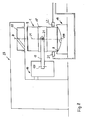
- a basic structure of a device for the invention Show traversing of a flat can during the filling process Figure 7 and 7a.
- a flat jug 1 hangs under the turntable 22 of a stretch 23.
- One of the end walls of the flat can is to recognize.
- the sliver delivers the sliver to the turntable 22, the sliver (here for reasons of clarity not shown) in the flat can 1.
- the traversing device 16 detects the flat can 1, each with a gripper arm and its swiveling gripper plate on the end wall.
- Figure 7a shows a view of the longitudinal walls of the Flat jug. It can be seen more clearly there that the flat can 1 is clamped and held between the gripper plates 18, 18 '. A condition for changing the can is shown.
- the gripper plates 18, 18 ' are pivotable and resettable in their Gripper arms 17, 17 'mounted. This storage corresponds to one Swivel axis, the axis A2.
- the gripper arm 17 can, for example, in the traversing device 16 can be arranged pivotably about a vertical axis 170, so that he from a starting position (parallel to the rail 160 Figure 7a) around Can be swiveled 90 ° to grip and hold the flat jug ( Figure 7).
- the gripper arm 17 ' is in position strongly gripped for gripping and holding, i.e. the gripper arm 17 ' forms a stop for the new one to be inserted when changing the can Flat jug. This has the advantage that the flat can thus is positioned opposite the traversing device.
- the flat can 1 is held by the traversing device 16 and shifts.
- the traversing takes place along a rail 160 which corresponds to a traverse path with the reversal points.
- the can wall there is an upper can area on both sides oKB and a lower can area uKB shown.
- the upper can area oKB is an area between the upper can rim and a gripper plate holding the flat can lies.
- the lower can area oKB is an area between the lower edge of the can and one holding the flat can Gripper plate is.
- Swivel encoder S1, S2 can be arranged.
- the swivel encoders S1, S2 can be arranged in the upper can area oKB.
- FIG. 7 shows a possible arrangement of the pivot sensors S1 and S2 uKB in the lower can area.
- the swiveling device SV is formed in the example according to FIG. 7 by slew encoders S1, S2 and axis A2. This swivel device SV is arranged with the traversing device 16.
- the swivel sensors S1, S2 arranged.
- the rotary encoders S1, S2 have none Contact with the flat jug 1.
- the rotary encoders S1, S2 put into operation, i.e. they give the Flat can in the lower area uKB a guide.
- the swivel encoders S1, S2 thus have the option of the flat jug in the basic position center or swivel into a swiveled position and give guidance in this swiveled position.
- the swivel sensors are shown in FIG S1, S2 activated so that the flat can in the lower area swivel right or left around axis A2 and in one these swivel positions when traversing to the opposite Lead the return path.
- the flat can 1 After the filling process is complete Returned the flat can 1 to its basic position G, i.e. she hangs and can be placed on a ready-made can magazine trolley (not shown) are transported. An empty jug is from Can magazine trolley in the basic position G below the turntable 22 hanged.
- the flat jug stands 1 on a conveyor track 19.
- the conveyor track 19 is like this designed that they both the traversing movement and the Can ensure pivoting movement of the flat can 1.
- the touch area 190 of the transport track 19 is concave.
- the concave contact surface has its apex line at the lowest level. Due to this concave design of the contact surface 190 the flat can is on one side with the lower can 8 elongated side walls on the contact surface 190. That has the advantage that the contact surface 190 is both a changierals also a swiveling movement of the flat can without additional constructive effort.
- the transport track 19 thus has also no portable assemblies such as pushcars necessary to perform the pivoting movement of the flat can.
- FIG 9 shows a detailed embodiment of the swivel device with a transport path.
- the flat can 1 is seen with the narrow end face.
- the flat can 1 stands on the transport path 19.
- the transport path 19 consists of individual, rotatably mounted rollers which are arranged side by side over the entire length of the traversing path.
- the roles 206 and 207 are shown as representative of this. It can be seen that these rollers are inclined relative to the base 6 at an angle which can be, for example, 12 °.
- the rollers 206, 207 are arranged with their surface line in such a way that the surface line simulates cutouts from the concavely inclined contact surface 190.
- the flat can 1 Due to this inclination of the rollers, the flat can 1 with its can bulge 8, which delimit the elongated side walls 2 and 3, stands on the right rollers (symbolized by the roller 207) and on the left rollers (symbolized by the roller 206).
- the flat can In the position shown, the flat can is in its basic position G.
- the central perpendicular M of the flat can 1 coincides with the vertical L of the base area 6 (cf. FIG. 2).
- this basic position G the flat can 1 is located, for example, immediately before the filling process begins.
- the turntable 22 is also still in the rest position.
- the traversing device 16 has its own drive 24 Control that transfers power to a clutch mechanism 161.
- the clutch mechanism 161 allows the traversing device 16 are moved on the rail 160 can.
- clutch mechanism 161 receives a signal in a known manner for mutual coupling, so that a reversal of the direction of travel becomes possible.
- the traversing device 16 has the vertical one Swivel axis 170 pivotable gripper arm 17 in the direction of the narrow Front of the flat can 1 pivoted.
- the gripper arm 17 has the opposite one in FIG. 9 not visible end face detected. Limit the further explanations on the gripper arm 17 shown here, they apply but analogously for the other gripper arm not visible in the picture 17 '.
- the gripper arm 17 has a gripper plate 18 which End wall of the flat can 1 includes a form fit.
- the gripper plate 18 is in the gripper arm 17 by means of the axis 21 pivoted.
- the axis 21 realizes the analog Function of a swivel axis A2.
- FIG. 9 also shows two sliding bars as possible swivel sensors 202, 203, arranged in the lower can area uKB are.
- Each of the slide bars 202, 203 has a length that exceeds the The length of the flat can is sufficient.
- individual roles are arranged side by side.
- the axes of rotation these rollers are inclined at an angle to the perpendicular M.
- FIG. 10 shows the illustration.
- the illustration is schematic and shows a section from the transport track 19 and the assignment of the sliding bar 203.
- the partial transport track 19 is inclined Rollers 206, 206 'and 206' 'marked. Above this
- the sliding bar 203 is arranged to roll. He's wearing one Frame the rollers 204, 204 'and 204' '. These roles are with its axis of rotation in a plane that is angled approx.
- This sliding bar 203 is in the transverse direction Transport track 19 freely movable.
- the opposite (in Figure 10 not shown) sliding bar 202 is in the transverse direction versatile.
- the axes of rotation of the rollers of both sliding beams are inclined to each other so that their imaginary extension of the axes of rotation over the conveyor track.
- the two sliding bars 202, 203 can be controlled by controller 210 in such a way that their movements can be controlled independently of one another, thus it becomes possible not only to vary the angular amount, but also to realize unequal angles ⁇ and ⁇ when swiveling. This gives the possibility of making one of the two angles larger or keep it smaller than the remaining angle. So could an offset of the perpendicular perpendicular M to the axis of rotation D of the turntable be balanced.
- the sliding bar 202 stands with the pneumatic cylinder 200 in Connection, the same applies to the slide bar 203 and the pneumatic cylinder 201. Obtained depending on a control 210 the pneumatic cylinders 200, 201 via the pneumatic line 208, 209 compressed air supplied, so that the sliding bar 202, 203 accordingly moved towards or away from the inclined position of the jug can be.
- the flat can placed on the conveyor track 19 can thus be centered in a basic position G.
- the flat can is to bring it into a swiveled position.
- the control 210 of the pneumatic cylinder 201 Compressed air is relieved and in return the pneumatic cylinder 200 definitely loaded with compressed air.
- This interplay of the pneumatic cylinders 200, 201 causes the lower half of the Flat can 1 pivoted about axis 21 in the direction of the left side of the image becomes.
- the can rim with can 8 of the can wall 3 slide on the rollers (symbolic in Figure 9, roller 206 shown) upwards, while the can rim with can 8 the can wall 2 on the rollers (symbolic in FIG. 9, Roll 207 shown) slides down. In this position kept the jug.
- the filling of the flat can begins in this position.
- the Flat jug is in the swiveled position to the opposite Reverse path changes. It slides along the rollers which are arranged in the sliding bar.
- the traversing device 16 recognizes that the flat can 1 the return path the swivel encoders with the Sliding bar activated. This is done by the fact that the pneumatic cylinder 201 is loaded with a defined force, during the pneumatic cylinder 200 also via the control 210 defined relief. Through these movements the pneumatic cylinder the sliding bar 203 pushes the lower edge of the can towards the right side of the picture ( Figure 9). The can rim slides down on the roll 206.
- Figure 11 shows a principle where the flat can on a flat Transport path 300 stands and this flat transport path 300 in turn is arranged in a concave transport path 301.
- a force F1, F2 is alternately applied by the swivel encoder, which leads to the fact that the transport path 300 within the Transport path 301 pivots.
- FIG. 12 shows in principle another embodiment. After In the present example, FIG. 12 does not cause the pivoting Use of the rotary encoder is achieved, but by the forced Guiding a flat can with the help of a rail system (403, 404, 405).
- the rail system is concave Transport track 40 arranged.
- the flat can 1 is mutual guided on the rails 403, 404 or 403, 405.
- the traversing is a switch (not here shown)
- the flat can from a rail 403, 404 on the other track 403, 405 and vice versa.
- the Flat jug is thus forcibly on the angled walls 401, 402 of the transport track 40.
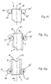
- FIG 14 shows a further advantageous embodiment of a Swivel encoder SG.
- the swivel encoder SG consists of a roller 50, which is mounted eccentrically in an axis 51.
- Figure 14 shows for example, that roller 50 with axis 51 below the machine table 52 of the sliver storage is arranged on a route. Under the machine table 52 is a flat can 1 for traversing arranged.
- the swivel encoder SG consists of an adjustment lever 53 with axis 54 and an adjusting device 55. Adjusting lever 53 with axis 54 and adjusting device 55 are above the Machine table 52 arranged and do not interfere with the movement of one Flat jug.
- the roller 50 consists in detail of an eccentric hub 56 which is arranged eccentrically in axis 51.
- the eccentric hub 56 is fixed by a detachable screw connection with the axis 51 connected.
- the eccentric hub 56 has an elongated hole 57 with an adjustable Grid. With slot 57 there is the possibility Eccentricity of the eccentric hub 56 is gradually adjustable and fixable close. An adjustment of the eccentricity can, for example become necessary if the can formats change or a change in the swivel angle may be necessary.
- the eccentric hub 56 has a ball bearing ring 58. On this ball bearing ring is rotatable a roller ring 59 with its outer surface 60 arranged.
- the axis 51 is fixed with an adjusting lever 53 connected.
- the adjusting lever 53 is rotatably mounted in the axis 54.
- the adjusting device 55 is mounted in the axis 54.
- the adjusting device 55 can be used, for example, as a pneumatic cylinder 61 with a piston rod 62. would be applicable however also other physically acting adjustment devices, for example, electromechanical or hydraulic adjusting devices.
- the piston rod 62 is in engagement with the axis 54.
- the pneumatic cylinder 61 is held by an angular body 63, which is fixed on the machine table 52.
- the pneumatic cylinder 61 also has a connection 64 for a control line, which leads to a control device.
- the swivel encoder SG is on both sides of the traversing path of a flat can, preferably on Reversal path arranged. The arrangement can optionally be in Near the lower can area or the upper can area. According to FIG. 14, the arrangement of the swivel encoder is, for example SG shown near the upper can area oKB.
- FIG. 16 shows a top view of the swivel encoder SG according to FIG 14.
- Figure 16 shows that roller 50 is between the position shown and the dashed position P swivel and adjustable is. For this purpose, the piston rod 62 must be pulled or pushed.
- FIGS. 15 to 15b show a flat jug, which is empty and placed in the change position with a can change is.
- Figures 15 to 15b show a representation with View of the storage surface from the lower side of the machine table 52 10 a flat jug with an upper jug rim 9.
- the two rollers 50, 50 'with their eccentric axis 51, 51' are arranged schematically in the upper can area, at the upper edge 9.
- the flat can is already in Change position and the rollers 50, 50 'by means of an adjusting device placed on the top of the can.
- the outer surface 60 the roller crown 59 lies against the can rim 9.
- the preparation 15a shows a traversing position of the flat can.
- the dashed The arrangement shows the state of the figure 15.
- the swivel encoder SG can also be used in the lower can area uKB become.
- the swivel encoder SG requires little construction Effort, is inexpensive and requires little maintenance.
Landscapes
- Coiling Of Filamentary Materials In General (AREA)
- Spinning Or Twisting Of Yarns (AREA)
- Treatment Of Fiber Materials (AREA)
- Preliminary Treatment Of Fibers (AREA)
Claims (7)
- Dispositif de va-et-vient pour un pot plat (1) pendant son remplissage à une machine textile délivrant du ruban de fibres, des éléments de retenue étant disposés sur un dispositif de va-et-vient (16) qui peut être déplacé le long d'un trajet de va-et-vient et le pot plat (1) étant disposé de façon suspendue entre les éléments de retenue, et un dispositif pivotant pivotant le pot plat (1), pendant l'inversion du trajet de va-et-vient, dans une position latérale, jusqu'à l'inversion opposée, pour le pivoter ensuite dans une position latérale opposée, caractérisé en ce que le pot plat (1) pend dans les éléments de retenue (17, 18; 17', 18') du dispositif de va-et-vient (16) de façon à pouvoir être pivoté, l'axe (A0, A1, A2, A3) positionné dans l'élément de retenue (17, 18; 17', 18') et destiné au pivotement du pot plat (1) étant mené, en ce qui concerne sa direction d'orientation, parallèlement au trajet de va-et-vient et que des mécanismes pivotant sont disposés à proximité immédiate du pot plat (1) qui agissent sur le pot plat.
- Dispositif selon la revendication 1, caractérisé en ce que les mécanismes pivotant (S1, S2; SG; 50, 50') sont disposés à proximité des parois longitudinales du pot plat (1).
- Dispositif selon la revendication 1, caractérisé en ce que l'axe constitue respectivement la liaison entre le bras de préhension (17, 17') et la plaque de préhension (18, 18') d'un élément de retenue.
- Dispositif selon la revendication 1 ou 2, caractérisé en ce que les mécanismes pivotant (S1, S2, 50, 50') constituent un guidage du pot plat en position pivotée.
- Dispositif selon la revendication 1 ou 2, caractérisé en ce que les mécanismes pivotant (S1, S2, 50, 50') centrent le pot plat dans la position de base (G) de celui-ci.
- Dispositif selon la revendication 1 ou 2, caractérisé en ce qu'un mécanisme pivotant est conçu comme rouleau rotatif excentrique (50) relié à un dispositif de réglage (61, 64).
- Dispositif selon la revendication 1ou 2, caractérisé en ce que les mécanismes pivotant (S1, S2, 50, 50') sont susceptibles d'être commandés au moyen d'un dispositif de commande.
Applications Claiming Priority (3)
| Application Number | Priority Date | Filing Date | Title |
|---|---|---|---|
| DE4324951A DE4324951A1 (de) | 1993-07-24 | 1993-07-24 | Verfahren zur Changierung einer Flachkanne während des Befüllens an einer Faserband abliefernden Textilmaschine und dessen Vorrichtung |
| DE4324951 | 1993-07-24 | ||
| EP94109057A EP0635448B1 (fr) | 1993-07-24 | 1994-06-14 | Procédé de va-et-vient pour un pot plat pendant son remplissage à une machine de textile délivrant des mèches et son dispositif |
Related Parent Applications (2)
| Application Number | Title | Priority Date | Filing Date |
|---|---|---|---|
| EP94109057.3 Division | 1994-06-14 | ||
| EP94109057A Division-Into EP0635448B1 (fr) | 1993-07-24 | 1994-06-14 | Procédé de va-et-vient pour un pot plat pendant son remplissage à une machine de textile délivrant des mèches et son dispositif |
Publications (3)
| Publication Number | Publication Date |
|---|---|
| EP0703178A2 EP0703178A2 (fr) | 1996-03-27 |
| EP0703178A3 EP0703178A3 (fr) | 1997-03-26 |
| EP0703178B1 true EP0703178B1 (fr) | 1999-01-20 |
Family
ID=6493666
Family Applications (2)
| Application Number | Title | Priority Date | Filing Date |
|---|---|---|---|
| EP95118583A Expired - Lifetime EP0703178B1 (fr) | 1993-07-24 | 1994-06-14 | Dispositif de va-et-vient pour un pot plat pendant son remplissage à une machine textile délivrant des mèches |
| EP94109057A Expired - Lifetime EP0635448B1 (fr) | 1993-07-24 | 1994-06-14 | Procédé de va-et-vient pour un pot plat pendant son remplissage à une machine de textile délivrant des mèches et son dispositif |
Family Applications After (1)
| Application Number | Title | Priority Date | Filing Date |
|---|---|---|---|
| EP94109057A Expired - Lifetime EP0635448B1 (fr) | 1993-07-24 | 1994-06-14 | Procédé de va-et-vient pour un pot plat pendant son remplissage à une machine de textile délivrant des mèches et son dispositif |
Country Status (6)
| Country | Link |
|---|---|
| US (1) | US5661947A (fr) |
| EP (2) | EP0703178B1 (fr) |
| JP (1) | JP3516354B2 (fr) |
| CZ (1) | CZ285664B6 (fr) |
| DE (3) | DE4324951A1 (fr) |
| RU (1) | RU94026073A (fr) |
Families Citing this family (4)
| Publication number | Priority date | Publication date | Assignee | Title |
|---|---|---|---|---|
| DE4416948A1 (de) * | 1994-05-13 | 1995-11-16 | Rieter Ingolstadt Spinnerei | Vorrichtung zum Schwenken einer changierenden Flachkanne an einer Strecke |
| EP1329541A3 (fr) | 1998-05-13 | 2003-08-27 | Maschinenfabrik Rieter Ag | Machine pour le traitement de matériau textile avec banc d'étirage |
| DE19831908A1 (de) * | 1998-07-16 | 2000-01-20 | Manfred Langen | Rechteckspinnkanne |
| KR102364998B1 (ko) * | 2021-07-23 | 2022-02-17 | 유한복 | 마스크 끈 제조장치 |
Family Cites Families (16)
| Publication number | Priority date | Publication date | Assignee | Title |
|---|---|---|---|---|
| GB325660A (en) * | 1929-01-08 | 1930-02-27 | Joshua Valentine Eves | Improvements in apparatus for coiling and packing the slivers of flax, hemp and similar fibres into cans or equivalent receptacles |
| GB812644A (en) * | 1956-09-04 | 1959-04-29 | Tmm Research Ltd | Improvements relating to the processing and packaging of textile slivers |
| BE571328A (fr) * | 1957-10-02 | |||
| FR1225360A (fr) * | 1958-05-30 | 1960-06-30 | Fleissner & Co G M B H | Dispositif d'empilage de pièces de longueur finie telles que bandes de tissus, voiles ou nappes de fibres, ou articles analogues, dans les machines textiles |
| US3339244A (en) * | 1962-06-19 | 1967-09-05 | Warner Swasey Co | Apparatus for packing sliver |
| FR1441502A (fr) * | 1965-02-19 | 1966-06-10 | Crylor | Procédé et appareil pour le bambanage de câbles de filaments continus ou de rubans de fibres discontinues |
| US3590257A (en) * | 1968-04-12 | 1971-06-29 | Teijin Ltd | Apparatus for automatically removing irregular yarn |
| DE1932621A1 (de) * | 1968-07-15 | 1970-01-22 | Leipzig Veb Druckmasch Werke | Einrichtung zum registergleichen Verbinden einer vorbedruckten Bahn |
| CH632721A5 (de) * | 1978-10-30 | 1982-10-29 | Heberlein Hispano Sa | Vorrichtung zum abfuellen eines faserstrangs in spinnkannen. |
| DE2913450A1 (de) * | 1979-04-04 | 1980-10-16 | Schlafhorst & Co W | Verfahren und vorrichtung zum ablegen von lunte in einen behaelter |
| DE3110440A1 (de) * | 1981-03-18 | 1982-10-07 | Trützschler GmbH & Co KG, 4050 Mönchengladbach | Faserbandablegeeinrichtung fuer eine karde, strecke o. dgl. |
| US4628972A (en) * | 1983-08-18 | 1986-12-16 | H. Daniel Doane | Apparatus for reconditioning drums |
| US4960156A (en) * | 1989-01-13 | 1990-10-02 | Howden Food Equipment, Inc. | Method and apparatus for topping off containers with liquid to predetermined headspace level |
| CH681450A5 (fr) * | 1990-05-18 | 1993-03-31 | Rieter Ag Maschf | |
| IT1238737B (it) * | 1990-05-30 | 1993-09-01 | Gualchierani System | Metodo ed apparecchiatura per il riempimento di contenitori di forma quadra o rettangolare per materiale tessile in stoppino o tops |
| DE4416948A1 (de) * | 1994-05-13 | 1995-11-16 | Rieter Ingolstadt Spinnerei | Vorrichtung zum Schwenken einer changierenden Flachkanne an einer Strecke |
-
1993
- 1993-07-24 DE DE4324951A patent/DE4324951A1/de not_active Ceased
-
1994
- 1994-06-14 DE DE59400759T patent/DE59400759D1/de not_active Expired - Fee Related
- 1994-06-14 DE DE59407705T patent/DE59407705D1/de not_active Expired - Fee Related
- 1994-06-14 EP EP95118583A patent/EP0703178B1/fr not_active Expired - Lifetime
- 1994-06-14 EP EP94109057A patent/EP0635448B1/fr not_active Expired - Lifetime
- 1994-07-08 JP JP15710394A patent/JP3516354B2/ja not_active Expired - Fee Related
- 1994-07-13 CZ CZ941691A patent/CZ285664B6/cs not_active IP Right Cessation
- 1994-07-22 RU RU94026073/12A patent/RU94026073A/ru unknown
-
1996
- 1996-03-27 US US08/622,926 patent/US5661947A/en not_active Expired - Fee Related
Also Published As
| Publication number | Publication date |
|---|---|
| EP0635448B1 (fr) | 1996-10-02 |
| CZ169194A3 (en) | 1995-02-15 |
| EP0635448A1 (fr) | 1995-01-25 |
| US5661947A (en) | 1997-09-02 |
| DE4324951A1 (de) | 1995-01-26 |
| CZ285664B6 (cs) | 1999-10-13 |
| DE59400759D1 (de) | 1996-11-07 |
| JPH07237818A (ja) | 1995-09-12 |
| EP0703178A3 (fr) | 1997-03-26 |
| DE59407705D1 (de) | 1999-03-04 |
| JP3516354B2 (ja) | 2004-04-05 |
| EP0703178A2 (fr) | 1996-03-27 |
| RU94026073A (ru) | 1996-09-27 |
Similar Documents
| Publication | Publication Date | Title |
|---|---|---|
| DE69117208T2 (de) | Vorrichtung zur Einstellung der Maschenlänge auf einer Flachstrickmaschine | |
| DE3410470A1 (de) | Vorrichtung zum transport von verpackungsmaterial-bahnen | |
| EP1711420A2 (fr) | Dispositif de stockage dynamique d'objets | |
| EP0681980B1 (fr) | Dispositif pour pivoter un pot plat de va-et-vient d'une machine textile délivrant des mèches | |
| EP0592828A1 (fr) | Pot plat de filature | |
| DE2944331A1 (de) | Rollen-verpackungsvorrichtung | |
| DE3416033C2 (fr) | ||
| EP0031821B1 (fr) | Dispositif de bobinage pour fils | |
| DE69900527T2 (de) | Automatische Vorrichtung zum Sammeln und Packen von von einer Karde produziertem Faserband in eine Kanne | |
| EP0703178B1 (fr) | Dispositif de va-et-vient pour un pot plat pendant son remplissage à une machine textile délivrant des mèches | |
| CH691475A5 (de) | Vorrichtung zum Füllen einer Kanne mit länglichem Querschnitt an einer Spinnereimaschine. | |
| EP0718223B1 (fr) | Dispositif de transfert pour marchandises, notamment pour boítes | |
| WO2017025155A1 (fr) | Dispositif de remplissage d'un pot de filature avec un ruban de fibres | |
| DE2715194C3 (de) | Vorrichtung zum Schwenken einer sich horizontal auf einem Luftkissentisch bewegenden Glasscheibe in ihrer Ebene | |
| DE2610084C2 (de) | Verfahren und Vorrichtung zum Wickeln konischer Kreuzspulen | |
| DE1901638B2 (de) | Vorrichtung zum automatischen auswechseln voller spulen gegen leere spulenhuelsen fuer ringspinn- und ringzwirnmaschinen | |
| DE1560012B2 (de) | Vorrichtung zum auslegen von gewebebahnen | |
| DE3316479C2 (de) | Maschine zum Ein- und Auspacken von Kleinpackungen in oder aus oben offenen Transportgebinden | |
| EP0593951A2 (fr) | Dispositif de filature | |
| DE493319C (de) | Vorrichtung zum faltenartigen Ablegen der Lunte in Kannen | |
| DE4406488C1 (de) | Vorspinnmaschine | |
| WO1991013822A1 (fr) | Dispositif de tuyeres de transport pour margeurs rapides | |
| DE2519341C2 (de) | Vorrichtung zum Beladen mehrerer in einem Ablagegestell angeordneter Tragplatten mit blattartigen Gegenständen | |
| DE3729776C2 (de) | Verfahren und Vorrichtung zum Entnehmen von Kreuzspulen aus dem Spulenrahmen und zum Ablegen auf eine Kreuzspulenempfangsvorrichtung | |
| EP0629574A1 (fr) | Dispositif de chargement pour du matériau, en particulier pour des bobines de papier |
Legal Events
| Date | Code | Title | Description |
|---|---|---|---|
| PUAI | Public reference made under article 153(3) epc to a published international application that has entered the european phase |
Free format text: ORIGINAL CODE: 0009012 |
|
| 17P | Request for examination filed |
Effective date: 19951125 |
|
| AC | Divisional application: reference to earlier application |
Ref document number: 635448 Country of ref document: EP |
|
| AK | Designated contracting states |
Kind code of ref document: A2 Designated state(s): DE ES IT |
|
| PUAL | Search report despatched |
Free format text: ORIGINAL CODE: 0009013 |
|
| AK | Designated contracting states |
Kind code of ref document: A3 Designated state(s): DE ES IT |
|
| 17Q | First examination report despatched |
Effective date: 19970602 |
|
| GRAG | Despatch of communication of intention to grant |
Free format text: ORIGINAL CODE: EPIDOS AGRA |
|
| GRAG | Despatch of communication of intention to grant |
Free format text: ORIGINAL CODE: EPIDOS AGRA |
|
| GRAH | Despatch of communication of intention to grant a patent |
Free format text: ORIGINAL CODE: EPIDOS IGRA |
|
| GRAH | Despatch of communication of intention to grant a patent |
Free format text: ORIGINAL CODE: EPIDOS IGRA |
|
| GRAA | (expected) grant |
Free format text: ORIGINAL CODE: 0009210 |
|
| AC | Divisional application: reference to earlier application |
Ref document number: 635448 Country of ref document: EP |
|
| AK | Designated contracting states |
Kind code of ref document: B1 Designated state(s): DE ES IT |
|
| PG25 | Lapsed in a contracting state [announced via postgrant information from national office to epo] |
Ref country code: ES Free format text: THE PATENT HAS BEEN ANNULLED BY A DECISION OF A NATIONAL AUTHORITY Effective date: 19990120 |
|
| ITF | It: translation for a ep patent filed | ||
| REF | Corresponds to: |
Ref document number: 59407705 Country of ref document: DE Date of ref document: 19990304 |
|
| PLBE | No opposition filed within time limit |
Free format text: ORIGINAL CODE: 0009261 |
|
| STAA | Information on the status of an ep patent application or granted ep patent |
Free format text: STATUS: NO OPPOSITION FILED WITHIN TIME LIMIT |
|
| 26N | No opposition filed | ||
| PG25 | Lapsed in a contracting state [announced via postgrant information from national office to epo] |
Ref country code: IT Free format text: LAPSE BECAUSE OF NON-PAYMENT OF DUE FEES;WARNING: LAPSES OF ITALIAN PATENTS WITH EFFECTIVE DATE BEFORE 2007 MAY HAVE OCCURRED AT ANY TIME BEFORE 2007. THE CORRECT EFFECTIVE DATE MAY BE DIFFERENT FROM THE ONE RECORDED. Effective date: 20050614 |
|
| PGFP | Annual fee paid to national office [announced via postgrant information from national office to epo] |
Ref country code: DE Payment date: 20050629 Year of fee payment: 12 |
|
| PG25 | Lapsed in a contracting state [announced via postgrant information from national office to epo] |
Ref country code: DE Free format text: LAPSE BECAUSE OF NON-PAYMENT OF DUE FEES Effective date: 20070103 |