EP0703321B2 - Arbeitsgerät mit Schwenkantrieb für Baumaschinen - Google Patents
Arbeitsgerät mit Schwenkantrieb für Baumaschinen Download PDFInfo
- Publication number
- EP0703321B2 EP0703321B2 EP95105337A EP95105337A EP0703321B2 EP 0703321 B2 EP0703321 B2 EP 0703321B2 EP 95105337 A EP95105337 A EP 95105337A EP 95105337 A EP95105337 A EP 95105337A EP 0703321 B2 EP0703321 B2 EP 0703321B2
- Authority
- EP
- European Patent Office
- Prior art keywords
- housing
- work tool
- motor
- plates
- upper side
- Prior art date
- Legal status (The legal status is an assumption and is not a legal conclusion. Google has not performed a legal analysis and makes no representation as to the accuracy of the status listed.)
- Expired - Lifetime
Links
- 238000010276 construction Methods 0.000 title claims description 11
- 210000000056 organ Anatomy 0.000 description 2
- 230000005540 biological transmission Effects 0.000 description 1
- 238000009434 installation Methods 0.000 description 1
Images




Classifications
-
- E—FIXED CONSTRUCTIONS
- E02—HYDRAULIC ENGINEERING; FOUNDATIONS; SOIL SHIFTING
- E02F—DREDGING; SOIL-SHIFTING
- E02F9/00—Component parts of dredgers or soil-shifting machines, not restricted to one of the kinds covered by groups E02F3/00 - E02F7/00
- E02F9/20—Drives; Control devices
- E02F9/22—Hydraulic or pneumatic drives
- E02F9/2264—Arrangements or adaptations of elements for hydraulic drives
- E02F9/2275—Hoses and supports therefor and protection therefor
-
- E—FIXED CONSTRUCTIONS
- E02—HYDRAULIC ENGINEERING; FOUNDATIONS; SOIL SHIFTING
- E02F—DREDGING; SOIL-SHIFTING
- E02F3/00—Dredgers; Soil-shifting machines
- E02F3/04—Dredgers; Soil-shifting machines mechanically-driven
- E02F3/28—Dredgers; Soil-shifting machines mechanically-driven with digging tools mounted on a dipper- or bucket-arm, i.e. there is either one arm or a pair of arms, e.g. dippers, buckets
- E02F3/36—Component parts
- E02F3/3604—Devices to connect tools to arms, booms or the like
- E02F3/3677—Devices to connect tools to arms, booms or the like allowing movement, e.g. rotation or translation, of the tool around or along another axis as the movement implied by the boom or arms, e.g. for tilting buckets
Definitions
- the invention relates to an implement, in particular a bucket or the like to connect with a stick of a construction machine on his Top with a centrally located attachment
- Has pivoting device that as a rotary motor Housing is formed, the shaft with a receiving device at the top of the implement connected is.
- Excavator bucket and especially trench clearing bucket are usually about hydraulic piston-cylinder units attached to the end of the excavator handle, so that pivoting movements about the transverse axis of the spoon can be executed.
- a disadvantage of such constructions is the fact that the hydraulic units very susceptible to damage in harsh operations and are therefore protected must be accommodated. Because of the long Power transmission paths are also those on the Fork edge of the bucket acting forces limited.
- a trench clearing spoon of the one outlined at the beginning Type is known from DE-A 42 09 412. There it is Attachment via a welded swivel head connected to the excavator bucket, in which A rotating motor is suspended from the swivel head Fastening a relatively weak flange serves, which is fixed in the swivel head.
- the Welded construction of the swivel head is proportionate vulnerable and must all be transferred from the backhoe Absorb forces. Furthermore, there are no precautions hit, which make it possible to counter the backhoe swap another one or in simpler Way to attach to another excavator arm.
- EP 0 356 738 B1 shows a shovel that can be releasably shifted to a receptacle device is attached, on which in turn the shaft of a motor by means of several screws distributed in the circumferential direction is fixed.
- the time of US 5,327,812 is that Instead, use several screws arranged parallel in the radial direction established.
- the invention is based on the object Tools of the genre outlined at the beginning are available to put, its attachment with swivel device is much more robust and that Possibility to be expanded if necessary to replace it with another implement or to attach to another stem.
- the receiving device of the implement in a manner known per se from two to one another parallel, protruding from the top of the implement Plates, the cutouts for releasable engagement the motor shaft.
- On the rotary motor can then be another implement can be grown, for example a hammer or a CombiCutter.
- a characteristic feature of claim 1 grips one end of the motor shaft in the recess one of the two plates one while the other End of the motor shaft in the elongated hole that is open at the top trained recess of the other plate used is at this end via a mounting plate is screwed tight.
- the rotary motor from above into the receiving device use, it is provided that the distance of the two plates around the one from the rotary motor protruding projection of the form-fitting into the recess engaging shaft end is larger than that Length of the case.
- the distance between the two ends corresponds to the length the housing of the rotary motor, the shaft ends essentially flush with the end faces of the housing to lock.
- the two shaft ends and the plates of the receiving device lying against it are connected to each other via screw bushings, the one lying against the outside of the plate Have flange that screwed detachably to the plate is.
- an implement according to the The present invention is the housing of the rotary motor directly on the underside of the attachment organ releasably attached.
- the rotary motor is an integrated one Component of the implement and replaces the previously common, welded swivel head.
- the motor housing takes over immediately forces acting between the handle and the implement can assume much higher values than previously usual designs with swivel head.
- the flat top of the housing of the rotary motor is designed so that it is at the bottom of the Attachment element is attached and detachable with screws this is connected.
- the implement for example an excavator spoon or trench clearing bucket to be removed from the handle of the construction machine and on another within a very short time Fasten construction machine type.
- the preferably hydraulic rotary motor has on its flat top connections for hydraulic Pipes protected by the attachment in Way to the hydraulics of the construction machine can be.
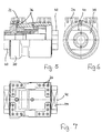
- FIGS 1 to 4 show a as a bucket 10 trained implement, which is a longitudinal extension transverse central axis swiveling be connected to the handle of a construction machine can.
- 10 is on the top of the excavator bucket a receptacle 12 firmly attached, the a front plate 14 and a parallel, rear Plate 16 is made. Between these two plates 14 and 16, a hydraulic rotary motor 18 is used, which has a housing 20 and in the figures 5 to 7 is shown in more detail.
- the housing 20 has one flat top 22 with threaded holes 24 and is via screws 26 on the flat underside of an attachment 28 attached.
- the attachment organ consists of a flat one, by means of the screws 26 on the top 22 of the housing 20 attached plate 30, of the two parallel legs 32 protrude upwards. through this attachment 26 is the bucket 10 on a stick attached to a construction machine.
- Figure 1 shows that through the attachment 28 hydraulic lines 34 are guided, the Ends to terminals 36 on the flat top 22 of the hydraulic rotary motor 18 lead.
- FIGS. 1 to 8 are the ends 38 and 40 of the shaft 42 of the rotary motor 18 over the housing 20 before. At least one the two protruding ends 38 have two to each other parallel flats 44, which in FIGS. 1 and 6 are recognizable. This flattened end 38 engages positively in a corresponding recess 46 the front plate 14 with which this shaft end 38 is secured by two screws 48.
- FIGS 3 and 4 show the bucket 10 from the back, where you can see that in the rear plate 16 has a recess which is an elongated hole 50 open at the top. In this slot 50 engages the other end 40 of the shaft 42. Like the figures 4 and 8 show, is at this shaft end 40 one circular disk-shaped mounting plate 52 attached, which via screws 54 to the back plate 16 is firmly connected.
Landscapes
- Engineering & Computer Science (AREA)
- Mining & Mineral Resources (AREA)
- Civil Engineering (AREA)
- General Engineering & Computer Science (AREA)
- Structural Engineering (AREA)
- Mechanical Engineering (AREA)
- Earth Drilling (AREA)
- Consolidation Of Soil By Introduction Of Solidifying Substances Into Soil (AREA)
- Load-Engaging Elements For Cranes (AREA)
Description
Claims (7)
- Arbeitsgerät, insbesondere Baggerlöffel oder dgl., das zur Verbindung mit einem Stiel einer Baumaschine an seiner Oberseite ein mittig angeordnetes Anbauorgan mit Schwenkeinrichtung aufweist, die als Drehmotor mit Gehäuse ausgebildet ist, dessen Welle mit einer Aufnahmeeinrichtung an der Oberseite des Arbeitsgerätes verbunden ist,
wobei das Gehäuse (20) des Drehmotors (18) unmittelbar an der Unterseite des Anbauorgans (28) lösbar befestigt ist, dadurch gekennzeichnet, daß die Aufnahmeeinrichtung (12) des Arbeitsgerätes (10) in an sich bekannter Weise aus zwei zueinander parallelen, von der Oberseite des Arbeitsgerätes abstehenden Platten (14, 16) besteht, die Aussparungen (46, 50) für den lösbaren Eingriff der Motorwelle (42) hat und
daß ein Ende (38) der Motorwelle (42) formschlüssig in die Aussparung (46) einer der beiden Platten (14) eingreift, während das andere Ende (40) der Motorwelle (42) in die als oben offenes Langloch (50) ausgebildete Aussparung der anderen Platte (16) eingesetzt ist, an der dieses Ende (40) über eine Befestigungsplatte (52) festgeschraubt ist. - Arbeitsgerät nach Anspruch 1, dadurch gekennzeichnet, daß der Abstand der beiden Platten (14, 16) um den aus dem Drehmotor (18) vorstehenden Überstand des formschlüssig in die Aussparung (46) eingreifenden Wellenendes (38) größer als die Länge des Gehäuses (20) ist.
- Arbeitsgerät, insbesondere Baggerlöffel oder dgl., das zur Verbindung mit einem Stiel einer Baumaschine an seiner Oberseite ein mittig angeordnetes Anbauorgan mit Schwenkeinrichtung aufweist, die als Drehmotor mit Gehäuse ausgebildet ist, dessen Welle mit einer Aufnahmeeinrichtung an der Oberseite des Arbeitsgerätes verbunden ist,
wobei das Gehäuse (20) des Drehmotors (18) unmittelbar an der Unterseite des Anbauorgans (28) lösbar befestigt ist, dadurch gekennzeichnet, daß die Aufnahmeeinrichtung (12) des Arbeitsgerätes (10) in an sich bekannter Weise aus zwei zueinander parallelen, von der Oberseite des Arbeitsgerätes abstehenden Platten (14, 16) besteht, die Aussparungen (46, 50) hat und
daß der Abstand der beiden Platten (14, 16) der Länge des Gehäuses (20) des Drehmotors (18) entspricht, dessen Wellenenden (38, 40) i.w. bündig mit den Stirnseiten des Gehäuses (20) abschließen, und daß die Wellenenden (38, 40) und die daran anliegenden Platten (14, 16) der Aufnahmeeinrichtung (12) über Schraubbuchsen (56) miteinander verbunden sind, die jeweils in eine Aussparung (46; 50) einer Platte (14, 16) eingreifen und einen an der Außenseite der Platte (14, 16) anliegenden Flansch (60) aufweisen, der an der Platte (14, 16) lösbar festgeschraubt ist. - Arbeitsgerät nach Anspruch 1 oder 3, dadurch gekennzeichnet, daß die flache Oberseite (22) des Gehäuses (20) des Drehmotors (18) an der Unterseite des Anbauorgans (28) anliegt und über Schrauben (26) lösbar mit diesem verbunden ist.
- Arbeitsgerät nach Anspruch 1 oder 3, dadurch gekennzeichnet, daß der als hydraulischer Motor ausgebildete Drehmotor (18) an seiner flachen Oberseite (22) Anschlüsse (36) für hydraulische Leitungen (34) hat, die durch das Anbauorgan (28) geführt sind.
- Arbeitsgerät nach Anspruch 3, dadurch gekennzeichnet, daß der Abstand der beiden Platten (14, 16) der Länge des Gehäuses (20) des Drehmotors (18) entspricht, dessen Wellenenden (38, 40) i.w. bündig mit den Stirnseiten des Gehäuses (20) abschließen, und daß die Wellenenden (38, 40) und die daran anliegenden Platten (14, 16) der Aufnahmeeinrichtung (12) über Schraubbuchsen (56) miteinander verbunden sind, die jeweils einen an der Außenseite der Platte (14, 16) anliegenden Flansch (60) aufweisen, der an der Platte (14, 16) lösbar festgesch raubt ist.
- Arbeitsgerät nach einem der vorhergehenden Ansprüche, dadurch gekennzeichnet, daß der als hydraulischer Motor ausgebildete Drehmotor (18) an seiner flachen Oberseite (22) Anschlüsse (36) für hydraulische Leitungen (34) hat, die durch das Anbauorgan (28) geführt sind.
Applications Claiming Priority (2)
| Application Number | Priority Date | Filing Date | Title |
|---|---|---|---|
| DE9415512U DE9415512U1 (de) | 1994-09-24 | 1994-09-24 | Arbeitsgerät mit Schwenkantrieb für Baumaschinen |
| DE9415512U | 1994-09-24 |
Publications (3)
| Publication Number | Publication Date |
|---|---|
| EP0703321A1 EP0703321A1 (de) | 1996-03-27 |
| EP0703321B1 EP0703321B1 (de) | 2000-03-15 |
| EP0703321B2 true EP0703321B2 (de) | 2004-09-15 |
Family
ID=6914130
Family Applications (1)
| Application Number | Title | Priority Date | Filing Date |
|---|---|---|---|
| EP95105337A Expired - Lifetime EP0703321B2 (de) | 1994-09-24 | 1995-04-08 | Arbeitsgerät mit Schwenkantrieb für Baumaschinen |
Country Status (3)
| Country | Link |
|---|---|
| EP (1) | EP0703321B2 (de) |
| AT (1) | ATE190687T1 (de) |
| DE (2) | DE9415512U1 (de) |
Families Citing this family (2)
| Publication number | Priority date | Publication date | Assignee | Title |
|---|---|---|---|---|
| DE19806057C2 (de) * | 1998-02-13 | 2002-11-28 | Franz Wimmer | Baumaschinenadapter |
| DE20315873U1 (de) * | 2003-10-15 | 2005-02-24 | Rädlinger Maschinen- und Anlagenbau GmbH | Hydraulischer Drehmotor |
Family Cites Families (2)
| Publication number | Priority date | Publication date | Assignee | Title |
|---|---|---|---|---|
| US4906161A (en) * | 1987-11-30 | 1990-03-06 | Weyer Paul P | Tiltable bucket assembly |
| DE4209412A1 (de) * | 1991-09-27 | 1993-04-01 | Lewin Heinz Ulrich | Anbauteil fuer bagger mit schwenkmotor |
-
1994
- 1994-09-24 DE DE9415512U patent/DE9415512U1/de not_active Expired - Lifetime
-
1995
- 1995-04-08 DE DE59507993T patent/DE59507993D1/de not_active Expired - Fee Related
- 1995-04-08 AT AT95105337T patent/ATE190687T1/de not_active IP Right Cessation
- 1995-04-08 EP EP95105337A patent/EP0703321B2/de not_active Expired - Lifetime
Also Published As
| Publication number | Publication date |
|---|---|
| DE9415512U1 (de) | 1994-12-22 |
| ATE190687T1 (de) | 2000-04-15 |
| EP0703321B1 (de) | 2000-03-15 |
| EP0703321A1 (de) | 1996-03-27 |
| DE59507993D1 (de) | 2000-04-20 |
Similar Documents
| Publication | Publication Date | Title |
|---|---|---|
| DE2602744C2 (de) | Zahn für Baggerlöffel von Erdbewegungsmaschinen | |
| DE2500217C3 (de) | Vorrichtung zum Anschließen auswechselbarer unterschiedlicher Arbeitswerkzeuge eines Baggers o.dgl | |
| DE2140111A1 (de) | Zweiteilige Schaufelkante für Flachbagger od. dgl | |
| EP3875692B1 (de) | Schnellwechsler für eine baumaschine | |
| EP3730697B2 (de) | Adapter für ein schnellwechselsystem und schnellwechselsystem mit einem solchen adapter | |
| EP0703321B2 (de) | Arbeitsgerät mit Schwenkantrieb für Baumaschinen | |
| EP2107166B1 (de) | Anbauplatte für Schnellwechselvorrichtung | |
| AT390645B (de) | Hammerschwenkvorrichtung | |
| DE7801553U1 (de) | Bearbeitungswerkzeug | |
| DE202017103198U1 (de) | Adapter für ein Schnellwechselsystem und Schnellwechselsystem mit einem solchen Adapter | |
| EP4502278A1 (de) | Schnellwechselsystem | |
| EP1727944B1 (de) | Arbeitswerkzeug für eine erdbaumaschine. | |
| DE19806057A1 (de) | Baumaschinenadapter | |
| DE3246002C2 (de) | ||
| EP1353011A1 (de) | Kopplungsvorrichtung zur lösbaren Kopplung eines Arbeitsgeräts mit einer Baumaschine | |
| AT413117B (de) | Anbauplatte für schnellwechselvorrichtung | |
| DE2458361A1 (de) | Montageanordnung fuer erdbearbeitungswerkzeuge | |
| DE29601727U1 (de) | Werkzeugwechselvorrichtung für Hydraulikbagger | |
| DE202005019913U1 (de) | Gesteinsbohrmaschine und Gesteinsbohrsystem | |
| DE3245894A1 (de) | Abstuetzeinrichtung fuer motorbetriebene werkzeuge, vorzugsweise fuer motorbetriebene gewindeschneidkluppen | |
| DE3637485C2 (de) | ||
| DE10138675B4 (de) | Anordnung zur Sicherung von Gelenkbolzen | |
| AT8070U1 (de) | Schnellwechselvorrichtung für bagger | |
| EP0393337A2 (de) | Bodenbearbeitungswerkzeug | |
| DE2538648C2 (de) | Meißel für Kohlenhobel |
Legal Events
| Date | Code | Title | Description |
|---|---|---|---|
| PUAI | Public reference made under article 153(3) epc to a published international application that has entered the european phase |
Free format text: ORIGINAL CODE: 0009012 |
|
| AK | Designated contracting states |
Kind code of ref document: A1 Designated state(s): AT BE CH DE DK ES FR GB GR IE IT LI LU MC NL PT SE |
|
| 17P | Request for examination filed |
Effective date: 19960313 |
|
| 17Q | First examination report despatched |
Effective date: 19980507 |
|
| GRAG | Despatch of communication of intention to grant |
Free format text: ORIGINAL CODE: EPIDOS AGRA |
|
| GRAG | Despatch of communication of intention to grant |
Free format text: ORIGINAL CODE: EPIDOS AGRA |
|
| GRAH | Despatch of communication of intention to grant a patent |
Free format text: ORIGINAL CODE: EPIDOS IGRA |
|
| GRAH | Despatch of communication of intention to grant a patent |
Free format text: ORIGINAL CODE: EPIDOS IGRA |
|
| GRAA | (expected) grant |
Free format text: ORIGINAL CODE: 0009210 |
|
| AK | Designated contracting states |
Kind code of ref document: B1 Designated state(s): AT BE CH DE DK ES FR GB GR IE IT LI LU MC NL PT SE |
|
| PG25 | Lapsed in a contracting state [announced via postgrant information from national office to epo] |
Ref country code: IT Free format text: LAPSE BECAUSE OF FAILURE TO SUBMIT A TRANSLATION OF THE DESCRIPTION OR TO PAY THE FEE WITHIN THE PRE;WARNING: LAPSES OF ITALIAN PATENTS WITH EFFECTIVE DATE BEFORE 2007 MAY HAVE OCCURRED AT ANY TIME BEFORE 2007. THE CORRECT EFFECTIVE DATE MAY BE DIFFERENT FROM THE ONE RECORDED.SCRIBED TIME-LIMIT Effective date: 20000315 Ref country code: GR Free format text: LAPSE BECAUSE OF NON-PAYMENT OF DUE FEES Effective date: 20000315 Ref country code: GB Free format text: LAPSE BECAUSE OF FAILURE TO SUBMIT A TRANSLATION OF THE DESCRIPTION OR TO PAY THE FEE WITHIN THE PRESCRIBED TIME-LIMIT Effective date: 20000315 Ref country code: FR Free format text: LAPSE BECAUSE OF FAILURE TO SUBMIT A TRANSLATION OF THE DESCRIPTION OR TO PAY THE FEE WITHIN THE PRESCRIBED TIME-LIMIT Effective date: 20000315 Ref country code: ES Free format text: THE PATENT HAS BEEN ANNULLED BY A DECISION OF A NATIONAL AUTHORITY Effective date: 20000315 |
|
| REF | Corresponds to: |
Ref document number: 190687 Country of ref document: AT Date of ref document: 20000415 Kind code of ref document: T |
|
| REG | Reference to a national code |
Ref country code: CH Ref legal event code: EP |
|
| REG | Reference to a national code |
Ref country code: CH Ref legal event code: NV Representative=s name: ISLER & PEDRAZZINI AG |
|
| PG25 | Lapsed in a contracting state [announced via postgrant information from national office to epo] |
Ref country code: LU Free format text: LAPSE BECAUSE OF NON-PAYMENT OF DUE FEES Effective date: 20000408 |
|
| PG25 | Lapsed in a contracting state [announced via postgrant information from national office to epo] |
Ref country code: IE Free format text: LAPSE BECAUSE OF NON-PAYMENT OF DUE FEES Effective date: 20000410 |
|
| REF | Corresponds to: |
Ref document number: 59507993 Country of ref document: DE Date of ref document: 20000420 |
|
| ET | Fr: translation filed | ||
| REG | Reference to a national code |
Ref country code: IE Ref legal event code: FG4D Free format text: GERMAN |
|
| PG25 | Lapsed in a contracting state [announced via postgrant information from national office to epo] |
Ref country code: PT Free format text: LAPSE BECAUSE OF FAILURE TO SUBMIT A TRANSLATION OF THE DESCRIPTION OR TO PAY THE FEE WITHIN THE PRESCRIBED TIME-LIMIT Effective date: 20000615 Ref country code: DK Free format text: LAPSE BECAUSE OF FAILURE TO SUBMIT A TRANSLATION OF THE DESCRIPTION OR TO PAY THE FEE WITHIN THE PRESCRIBED TIME-LIMIT Effective date: 20000615 |
|
| GBV | Gb: ep patent (uk) treated as always having been void in accordance with gb section 77(7)/1977 [no translation filed] |
Effective date: 20000315 |
|
| PG25 | Lapsed in a contracting state [announced via postgrant information from national office to epo] |
Ref country code: MC Free format text: LAPSE BECAUSE OF NON-PAYMENT OF DUE FEES Effective date: 20001031 |
|
| PLAV | Examination of admissibility of opposition |
Free format text: ORIGINAL CODE: EPIDOS OPEX |
|
| PLBI | Opposition filed |
Free format text: ORIGINAL CODE: 0009260 |
|
| PLBQ | Unpublished change to opponent data |
Free format text: ORIGINAL CODE: EPIDOS OPPO |
|
| PLBI | Opposition filed |
Free format text: ORIGINAL CODE: 0009260 |
|
| PLBQ | Unpublished change to opponent data |
Free format text: ORIGINAL CODE: EPIDOS OPPO |
|
| PLBI | Opposition filed |
Free format text: ORIGINAL CODE: 0009260 |
|
| PLAV | Examination of admissibility of opposition |
Free format text: ORIGINAL CODE: EPIDOS OPEX |
|
| 26 | Opposition filed |
Opponent name: FREDI STURY AG SCHWEISS- U. KONSTRUKTIONSWERKSTATT Effective date: 20001215 |
|
| PLBF | Reply of patent proprietor to notice(s) of opposition |
Free format text: ORIGINAL CODE: EPIDOS OBSO |
|
| REG | Reference to a national code |
Ref country code: IE Ref legal event code: MM4A |
|
| 26 | Opposition filed |
Opponent name: LEHNHOFF HARTSTAHL GMBH & CO. Effective date: 20001215 Opponent name: FREDI STURY AG SCHWEISS- U. KONSTRUKTIONSWERKSTATT Effective date: 20001215 |
|
| 26 | Opposition filed |
Opponent name: HELAC CORPORATION Effective date: 20001215 Opponent name: LEHNHOFF HARTSTAHL GMBH & CO. Effective date: 20001215 Opponent name: FREDI STURY AG SCHWEISS- U. KONSTRUKTIONSWERKSTATT Effective date: 20001215 |
|
| NLR1 | Nl: opposition has been filed with the epo |
Opponent name: HELAC CORPORATION Opponent name: LEHNHOFF HARTSTAHL GMBH & CO. Opponent name: FREDI STURY AG SCHWEISS- U. KONSTRUKTIONSWERKSTATT |
|
| PLBF | Reply of patent proprietor to notice(s) of opposition |
Free format text: ORIGINAL CODE: EPIDOS OBSO |
|
| PLBF | Reply of patent proprietor to notice(s) of opposition |
Free format text: ORIGINAL CODE: EPIDOS OBSO |
|
| PLBP | Opposition withdrawn |
Free format text: ORIGINAL CODE: 0009264 |
|
| PGFP | Annual fee paid to national office [announced via postgrant information from national office to epo] |
Ref country code: FR Payment date: 20040421 Year of fee payment: 10 |
|
| PGFP | Annual fee paid to national office [announced via postgrant information from national office to epo] |
Ref country code: SE Payment date: 20040426 Year of fee payment: 10 |
|
| PUAH | Patent maintained in amended form |
Free format text: ORIGINAL CODE: 0009272 |
|
| STAA | Information on the status of an ep patent application or granted ep patent |
Free format text: STATUS: PATENT MAINTAINED AS AMENDED |
|
| 27A | Patent maintained in amended form |
Effective date: 20040915 |
|
| AK | Designated contracting states |
Kind code of ref document: B2 Designated state(s): AT BE CH DE DK ES FR GB GR IE IT LI LU MC NL PT SE |
|
| REG | Reference to a national code |
Ref country code: CH Ref legal event code: AEN Free format text: AUFRECHTERHALTUNG DES PATENTES IN GEAENDERTER FORM |
|
| NLR2 | Nl: decision of opposition |
Effective date: 20040915 |
|
| NLR3 | Nl: receipt of modified translations in the netherlands language after an opposition procedure | ||
| EUG | Se: european patent has lapsed | ||
| PGFP | Annual fee paid to national office [announced via postgrant information from national office to epo] |
Ref country code: NL Payment date: 20050418 Year of fee payment: 11 |
|
| PGFP | Annual fee paid to national office [announced via postgrant information from national office to epo] |
Ref country code: BE Payment date: 20050421 Year of fee payment: 11 Ref country code: AT Payment date: 20050421 Year of fee payment: 11 |
|
| PGFP | Annual fee paid to national office [announced via postgrant information from national office to epo] |
Ref country code: CH Payment date: 20050422 Year of fee payment: 11 |
|
| PGFP | Annual fee paid to national office [announced via postgrant information from national office to epo] |
Ref country code: DE Payment date: 20050629 Year of fee payment: 11 |
|
| EN | Fr: translation not filed | ||
| PG25 | Lapsed in a contracting state [announced via postgrant information from national office to epo] |
Ref country code: AT Free format text: LAPSE BECAUSE OF NON-PAYMENT OF DUE FEES Effective date: 20060408 |
|
| PG25 | Lapsed in a contracting state [announced via postgrant information from national office to epo] |
Ref country code: LI Free format text: LAPSE BECAUSE OF NON-PAYMENT OF DUE FEES Effective date: 20060430 Ref country code: CH Free format text: LAPSE BECAUSE OF NON-PAYMENT OF DUE FEES Effective date: 20060430 Ref country code: BE Free format text: LAPSE BECAUSE OF NON-PAYMENT OF DUE FEES Effective date: 20060430 |
|
| PG25 | Lapsed in a contracting state [announced via postgrant information from national office to epo] |
Ref country code: NL Free format text: LAPSE BECAUSE OF NON-PAYMENT OF DUE FEES Effective date: 20061101 Ref country code: DE Free format text: LAPSE BECAUSE OF NON-PAYMENT OF DUE FEES Effective date: 20061101 |
|
| REG | Reference to a national code |
Ref country code: CH Ref legal event code: PL |
|
| NLV4 | Nl: lapsed or anulled due to non-payment of the annual fee |
Effective date: 20061101 |
|
| BERE | Be: lapsed |
Owner name: JOSEF RADLINGER MASCHINENBAU *RMB Effective date: 20060430 |
|
| PG25 | Lapsed in a contracting state [announced via postgrant information from national office to epo] |
Ref country code: SE Free format text: LAPSE BECAUSE OF NON-PAYMENT OF DUE FEES Effective date: 20050409 |
|
| PLAB | Opposition data, opponent's data or that of the opponent's representative modified |
Free format text: ORIGINAL CODE: 0009299OPPO |