EP0703326A1 - Elément de tension inoxydable pour la réalisation d'ouvrages en béton précontraint avec post-tension - Google Patents
Elément de tension inoxydable pour la réalisation d'ouvrages en béton précontraint avec post-tension Download PDFInfo
- Publication number
- EP0703326A1 EP0703326A1 EP95114352A EP95114352A EP0703326A1 EP 0703326 A1 EP0703326 A1 EP 0703326A1 EP 95114352 A EP95114352 A EP 95114352A EP 95114352 A EP95114352 A EP 95114352A EP 0703326 A1 EP0703326 A1 EP 0703326A1
- Authority
- EP
- European Patent Office
- Prior art keywords
- disk
- tension member
- tension
- holes
- armature
- Prior art date
- Legal status (The legal status is an assumption and is not a legal conclusion. Google has not performed a legal analysis and makes no representation as to the accuracy of the status listed.)
- Granted
Links
- 238000005260 corrosion Methods 0.000 title claims abstract description 12
- 230000007797 corrosion Effects 0.000 title claims abstract description 8
- 239000011513 prestressed concrete Substances 0.000 title claims description 4
- 238000007789 sealing Methods 0.000 claims abstract description 16
- 239000004033 plastic Substances 0.000 claims abstract description 7
- 229920003023 plastic Polymers 0.000 claims abstract description 7
- 229910000831 Steel Inorganic materials 0.000 claims abstract description 6
- 239000010959 steel Substances 0.000 claims abstract description 6
- 238000004873 anchoring Methods 0.000 claims description 21
- 239000000463 material Substances 0.000 claims description 11
- 150000001875 compounds Chemical class 0.000 claims description 8
- 210000002435 tendon Anatomy 0.000 claims description 6
- 239000011083 cement mortar Substances 0.000 claims description 3
- 239000002131 composite material Substances 0.000 claims description 2
- 230000001681 protective effect Effects 0.000 abstract description 2
- 239000004698 Polyethylene Substances 0.000 description 4
- 239000004567 concrete Substances 0.000 description 4
- 238000005253 cladding Methods 0.000 description 3
- 239000004519 grease Substances 0.000 description 3
- -1 polyethylene Polymers 0.000 description 3
- 239000004568 cement Substances 0.000 description 2
- 230000006835 compression Effects 0.000 description 2
- 238000007906 compression Methods 0.000 description 2
- 238000010276 construction Methods 0.000 description 2
- 230000003213 activating effect Effects 0.000 description 1
- 238000011161 development Methods 0.000 description 1
- 230000018109 developmental process Effects 0.000 description 1
- 229920001971 elastomer Polymers 0.000 description 1
- 239000003292 glue Substances 0.000 description 1
- 238000002347 injection Methods 0.000 description 1
- 239000007924 injection Substances 0.000 description 1
- 238000003780 insertion Methods 0.000 description 1
- 230000037431 insertion Effects 0.000 description 1
- 230000000149 penetrating effect Effects 0.000 description 1
- 229920001084 poly(chloroprene) Polymers 0.000 description 1
- 229920000573 polyethylene Polymers 0.000 description 1
- 125000006850 spacer group Chemical group 0.000 description 1
Images


Classifications
-
- E—FIXED CONSTRUCTIONS
- E04—BUILDING
- E04C—STRUCTURAL ELEMENTS; BUILDING MATERIALS
- E04C5/00—Reinforcing elements, e.g. for concrete; Auxiliary elements therefor
- E04C5/08—Members specially adapted to be used in prestressed constructions
- E04C5/12—Anchoring devices
-
- E—FIXED CONSTRUCTIONS
- E01—CONSTRUCTION OF ROADS, RAILWAYS, OR BRIDGES
- E01D—CONSTRUCTION OF BRIDGES, ELEVATED ROADWAYS OR VIADUCTS; ASSEMBLY OF BRIDGES
- E01D19/00—Structural or constructional details of bridges
- E01D19/14—Towers; Anchors ; Connection of cables to bridge parts; Saddle supports
Definitions
- the invention relates to a corrosion-protected tension member, primarily a tendon for prestressed concrete without composite according to the preamble of claim 1.
- prestressing In the construction of prestressed concrete structures, but especially in bridge structures, prestressing is known with and without bond. Prestressing with bond is usually carried out as prestressing with subsequent joining.
- the tendons are held longitudinally movable by arrangement in cladding tubes within the concrete cross-section until the concrete has hardened and, after tensioning, are injected into the remaining annular spaces in connection with the building by injecting cement glue.
- the tendons When prestressing without bond, the tendons are usually outside the concrete cross-section, but are supported against the building; they can be viewed at any time, retensioned and, if necessary, replaced.
- tension elements i.e. steel wire strands, which are each arranged in a sheath made of plastic, for example polyethylene, and are surrounded by a plastically deformable corrosion protection compound, e.g. grease, which fills the annular space between the tension element and sheath (DE. DE 37 34 954 C2).
- a plastically deformable corrosion protection compound e.g. grease
- the anchor pot itself is inserted into an anchor tube, which forms the tubular casing of the tension member in the anchoring area.
- an anchor tube which forms the tubular casing of the tension member in the anchoring area.
- the strands can be retightened and exchanged and it is still possible to pass the anchor pot Press cavity between the coverings of the strands and the inner wall of the tubular cover in the free area of the tension member with hardening material, in particular cement mortar.
- the invention has for its object to provide a simpler and more economical way of sealing the anchoring area of such a tension member from its free area, in which the cavity may also be wholly or partially with a hardening material, such as e.g. Cement paste, can be filled.
- a hardening material such as e.g. Cement paste
- the advantage of the invention is above all that the arrangement of the sealing plate immediately below the armature plate means that the previously required cavity filled with anti-corrosion compound can be completely dispensed with.
- the envelopes of the individual tension elements are brought through the sealing washer to the armature disk or introduced into it, so that the corrosion protection compound surrounding the individual elements within their envelopes directly adjoins the material filling the bores in the armature disk. Since the material still adhering to the individual elements in the anchoring area after the coverings have been removed is stripped off when the anchoring wedges are pushed on and fills the bores including the blind hole-like extensions, it is usually possible to dispense with additional filling of corrosion protection compound into the bores.
- the tension elements 2 consist of so-called monostrands, which are steel wire strands 3, which are used for protection against corrosion with coverings made of plastic, e.g. Envelope tubes 4, are provided and in which the cavity between the strands 3 and the envelope tubes 4 with a plastically deformable anti-corrosion compound, e.g. Fat, is filled.
- the strands 3 are anchored by means of multi-part ring wedges 5 in conical bores 6 in an armature disk 7 made of steel.
- the armature disk 7 is supported against an anchoring body 8 made of steel, which is embedded in a concrete component 9 and forms the tubular covering of the tension member 1 in this anchoring area.
- the tubular casing sits in connection with the anchoring body 8 in a trumpet 10 made of plastic, e.g. PE, to which then a cladding tube 11, again made of plastic, e.g. PE, is sealingly connected.
- the strands 3 with their envelopes 4 are passed through bores in a perforated disk 12, which in turn consists of plastic, primarily PE.
- the perforated disk 12 is interposed with a sealing disk 13 provided with corresponding bores and made of an elastically deformable material, such as e.g. Neoprene, on the side of the armature disk 7 facing away from the air side.
- Screw bolts 14 pass through the armature disk 7, the sealing disk 13 and the perforated disk 12 and permit the application of a surface pressure to the sealing disk 13, with the result of a transverse expansion causing a seal with respect to the envelopes 4 of the strands 2.
- the coverings 4 are removed over an end region of a certain length; at this point, the envelopes 4 extend into blind-hole-like extensions 6a of the bores 6 in the armature disk 7.
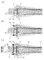
- FIGS. 3a to f shows individual successive working phases.
- the tensioning channel remaining within the tubular casing can be coated with a hardening material, e.g. Cement mortar to be filled in order to arrange and fix the individual elements 2. After this material has hardened, the prestress is applied.
- a hardening material e.g. Cement mortar
- the strands 3 with the coverings 4 are inserted into the anchoring body 8; they extend beyond the anchoring by the length L required for tensioning or anchoring.
- the perforated disk 12 and the sealing disk 13 have already been pushed onto the strands 3 with their envelopes 4.
- the strands 3 are stripped to a length l in the region of the protruding length L, that is, they are freed from the sheaths 4 in order to be able to anchor the strands 3 individually (FIG. 3b).
- the armature disk 7 is then pushed onto the exposed ends of the strands 3 (FIG. 3c), which is loosely connected to the perforated disk 12 with the sealing disk 13 interposed and pushed into the anchoring body 8 until it rests on its air-side support surface (FIG. 3d ). Since the sheaths 4 of the strands 3 can be shortened by temperature influences, it is recommended to leave the sheaths a little longer so that they come under compression pressure when the armature disk 7 is put on. The connection of the perforated disk 12 and the armature disk 7 takes place via the screw bolts 14.
Landscapes
- Engineering & Computer Science (AREA)
- Architecture (AREA)
- Civil Engineering (AREA)
- Structural Engineering (AREA)
- Reinforcement Elements For Buildings (AREA)
- Bridges Or Land Bridges (AREA)
Applications Claiming Priority (2)
| Application Number | Priority Date | Filing Date | Title |
|---|---|---|---|
| DE4433832 | 1994-09-22 | ||
| DE4433832A DE4433832A1 (de) | 1994-09-22 | 1994-09-22 | Korrosionsgeschütztes Zugglied, vornehmlich Spannglied für Spannbeton ohne Verbund |
Publications (2)
| Publication Number | Publication Date |
|---|---|
| EP0703326A1 true EP0703326A1 (fr) | 1996-03-27 |
| EP0703326B1 EP0703326B1 (fr) | 1999-11-03 |
Family
ID=6528892
Family Applications (1)
| Application Number | Title | Priority Date | Filing Date |
|---|---|---|---|
| EP95114352A Expired - Lifetime EP0703326B1 (fr) | 1994-09-22 | 1995-09-13 | Elément de tension inoxydable pour la réalisation d'ouvrages en béton précontraint avec post-tension |
Country Status (2)
| Country | Link |
|---|---|
| EP (1) | EP0703326B1 (fr) |
| DE (2) | DE4433832A1 (fr) |
Cited By (9)
| Publication number | Priority date | Publication date | Assignee | Title |
|---|---|---|---|---|
| WO1999036641A1 (fr) * | 1998-01-19 | 1999-07-22 | Suspa Spannbeton Gmbh | Dispositif d'ancrage pour ancre de tension et/ou ancre fixe |
| FR2783266A1 (fr) * | 1998-09-16 | 2000-03-17 | Spie Precontrainte | Organe d'ancrage remplacable, dispositif de protection mixte , systeme de precontrainte exterieure remplacable et ouvrage |
| RU2178489C1 (ru) * | 2001-04-02 | 2002-01-20 | Открытое акционерное общество "Мостотрест" | Устройство для сопряжения анкерного стакана и каналообразователя |
| US7174684B2 (en) | 2003-08-02 | 2007-02-13 | Dywidag-Systems International Gmbh | Corrosion-resistant tension member, particularly a tendon for prestressed concrete |
| US7181890B2 (en) | 2002-04-03 | 2007-02-27 | Dywidag-Systems International Gmbh | Anchoring device for a corrosion-resistant tension member, particularly an inclined cable for a cable-stayed bridge |
| KR101104212B1 (ko) * | 2008-06-04 | 2012-01-10 | 아주대학교산학협력단 | 프리스트레스 강선 정착 장치 |
| CN103147538A (zh) * | 2013-03-01 | 2013-06-12 | 柳州欧维姆机械股份有限公司 | 一种锚头密封结构组件 |
| DE102013215136A1 (de) | 2013-08-01 | 2015-02-05 | Dywidag-Systems International Gmbh | Korrosionsgeschütztes Zugglied und plastisch verformbare Scheibe aus Korrosionsschutzmaterial für ein derartiges Zugglied |
| CN104563395A (zh) * | 2015-01-06 | 2015-04-29 | 大连理工大学 | 一种体外预应力锚具防腐结构 |
Families Citing this family (7)
| Publication number | Priority date | Publication date | Assignee | Title |
|---|---|---|---|---|
| JPH1058726A (ja) * | 1996-06-13 | 1998-03-03 | Ricoh Co Ltd | 画像記録装置 |
| DE19833273A1 (de) * | 1998-07-24 | 2000-01-27 | Josef Eibl | Spanngliedanordnung |
| DE19918438A1 (de) * | 1999-04-23 | 2000-11-09 | Dyckerhoff & Widmann Ag | Korrosionsgeschütztes Stahlzugglied |
| EP2550400B2 (fr) | 2010-03-26 | 2023-06-14 | VSL International AG | Agencement d'étanchéité |
| KR20190097322A (ko) | 2011-04-15 | 2019-08-20 | 소레탄체 프레씨네트 | 멀티-텐돈 케이블 단부 보호방법 |
| CN111041970B (zh) * | 2019-12-17 | 2021-03-16 | 北京市第三建筑工程有限公司 | 预应力单耳拉索及其张拉方法 |
| CN113137007A (zh) * | 2021-04-27 | 2021-07-20 | 郑亮 | 一种碳纤维板锚具 |
Citations (8)
| Publication number | Priority date | Publication date | Assignee | Title |
|---|---|---|---|---|
| GB2148351A (en) * | 1983-10-19 | 1985-05-30 | Manuf Aceros Caucho Sa | Cable anchorage |
| DE3734954A1 (de) * | 1987-03-13 | 1988-04-07 | Dyckerhoff & Widmann Ag | Korrosionsgeschuetztes zugglied, vornehmlich spannglied fuer spannbeton ohne verbund und verfahren zu seinem einbau |
| DE3644551A1 (de) * | 1986-12-24 | 1988-07-07 | Zueblin Ag | Verankerung fuer ein verbundloses spannglied |
| EP0323285A1 (fr) * | 1987-11-25 | 1989-07-05 | Freyssinet International (Stup) | Perfectionnements aux ensembles constitués par un hauban et sa structure d'ancrage |
| DE3801451A1 (de) * | 1987-10-15 | 1989-08-03 | Dyckerhoff & Widmann Ag | Korrosionsgeschuetztes zugglied, vornehmlich spannglied fuer spannbeton ohne verbund |
| FR2628777A1 (fr) * | 1988-03-18 | 1989-09-22 | Vsl France | Dispositif d'ancrage de cables precontraints pour ouvrages du type maconnerie |
| DE9012786U1 (de) * | 1990-09-07 | 1990-11-08 | Dyckerhoff & Widmann AG, 8000 München | Spannbares Zugglied, insbesondere Spannglied für Spannbeton |
| DE4118897A1 (de) * | 1991-06-08 | 1992-12-10 | Hochtief Ag Hoch Tiefbauten | Bauwerkslagereinrichtung fuer ein spannglied und verfahren zum auswechseln eines solchen spanngliedes |
Family Cites Families (1)
| Publication number | Priority date | Publication date | Assignee | Title |
|---|---|---|---|---|
| DE3831518C2 (de) * | 1988-09-16 | 1994-12-22 | Holzmann Philipp Ag | Spannglied in polygonartiger Anordnung sowie Verfahren zum Einziehen des Spannglieds |
-
1994
- 1994-09-22 DE DE4433832A patent/DE4433832A1/de not_active Withdrawn
-
1995
- 1995-09-13 EP EP95114352A patent/EP0703326B1/fr not_active Expired - Lifetime
- 1995-09-13 DE DE59507171T patent/DE59507171D1/de not_active Expired - Lifetime
Patent Citations (10)
| Publication number | Priority date | Publication date | Assignee | Title |
|---|---|---|---|---|
| GB2148351A (en) * | 1983-10-19 | 1985-05-30 | Manuf Aceros Caucho Sa | Cable anchorage |
| DE3644551A1 (de) * | 1986-12-24 | 1988-07-07 | Zueblin Ag | Verankerung fuer ein verbundloses spannglied |
| DE3734954A1 (de) * | 1987-03-13 | 1988-04-07 | Dyckerhoff & Widmann Ag | Korrosionsgeschuetztes zugglied, vornehmlich spannglied fuer spannbeton ohne verbund und verfahren zu seinem einbau |
| DE3734954C2 (fr) | 1987-03-13 | 1992-07-09 | Dyckerhoff & Widmann Ag, 8000 Muenchen, De | |
| DE3801451A1 (de) * | 1987-10-15 | 1989-08-03 | Dyckerhoff & Widmann Ag | Korrosionsgeschuetztes zugglied, vornehmlich spannglied fuer spannbeton ohne verbund |
| EP0323285A1 (fr) * | 1987-11-25 | 1989-07-05 | Freyssinet International (Stup) | Perfectionnements aux ensembles constitués par un hauban et sa structure d'ancrage |
| EP0323285B1 (fr) | 1987-11-25 | 1992-05-13 | Freyssinet International (Stup) | Perfectionnements aux ensembles constitués par un hauban et sa structure d'ancrage |
| FR2628777A1 (fr) * | 1988-03-18 | 1989-09-22 | Vsl France | Dispositif d'ancrage de cables precontraints pour ouvrages du type maconnerie |
| DE9012786U1 (de) * | 1990-09-07 | 1990-11-08 | Dyckerhoff & Widmann AG, 8000 München | Spannbares Zugglied, insbesondere Spannglied für Spannbeton |
| DE4118897A1 (de) * | 1991-06-08 | 1992-12-10 | Hochtief Ag Hoch Tiefbauten | Bauwerkslagereinrichtung fuer ein spannglied und verfahren zum auswechseln eines solchen spanngliedes |
Cited By (9)
| Publication number | Priority date | Publication date | Assignee | Title |
|---|---|---|---|---|
| WO1999036641A1 (fr) * | 1998-01-19 | 1999-07-22 | Suspa Spannbeton Gmbh | Dispositif d'ancrage pour ancre de tension et/ou ancre fixe |
| FR2783266A1 (fr) * | 1998-09-16 | 2000-03-17 | Spie Precontrainte | Organe d'ancrage remplacable, dispositif de protection mixte , systeme de precontrainte exterieure remplacable et ouvrage |
| RU2178489C1 (ru) * | 2001-04-02 | 2002-01-20 | Открытое акционерное общество "Мостотрест" | Устройство для сопряжения анкерного стакана и каналообразователя |
| US7181890B2 (en) | 2002-04-03 | 2007-02-27 | Dywidag-Systems International Gmbh | Anchoring device for a corrosion-resistant tension member, particularly an inclined cable for a cable-stayed bridge |
| US7174684B2 (en) | 2003-08-02 | 2007-02-13 | Dywidag-Systems International Gmbh | Corrosion-resistant tension member, particularly a tendon for prestressed concrete |
| KR101104212B1 (ko) * | 2008-06-04 | 2012-01-10 | 아주대학교산학협력단 | 프리스트레스 강선 정착 장치 |
| CN103147538A (zh) * | 2013-03-01 | 2013-06-12 | 柳州欧维姆机械股份有限公司 | 一种锚头密封结构组件 |
| DE102013215136A1 (de) | 2013-08-01 | 2015-02-05 | Dywidag-Systems International Gmbh | Korrosionsgeschütztes Zugglied und plastisch verformbare Scheibe aus Korrosionsschutzmaterial für ein derartiges Zugglied |
| CN104563395A (zh) * | 2015-01-06 | 2015-04-29 | 大连理工大学 | 一种体外预应力锚具防腐结构 |
Also Published As
| Publication number | Publication date |
|---|---|
| DE4433832A1 (de) | 1996-03-28 |
| DE59507171D1 (de) | 1999-12-09 |
| EP0703326B1 (fr) | 1999-11-03 |
Similar Documents
| Publication | Publication Date | Title |
|---|---|---|
| DE3734954C2 (fr) | ||
| DE3437107C2 (fr) | ||
| EP0606820B1 (fr) | Dispositif d'ancrage d'au moins une armature de précontrainte dans une gaine et procédé pour monter le dispositif d'ancrage | |
| DE60010035T2 (de) | Verankerungsvorrichtung zum befestigen eines strukturkabels an einem bauteil | |
| EP0703326B1 (fr) | Elément de tension inoxydable pour la réalisation d'ouvrages en béton précontraint avec post-tension | |
| EP1505223B1 (fr) | Tendon protégé contre la corrosion, en particulier pour béton précontraint | |
| CH676617A5 (fr) | ||
| DE3224702C2 (de) | Vorrichtung zum Verankern und Koppeln eines Bündelspannglieds für Spannbeton | |
| DE8716679U1 (de) | Abstandhalter für ein spannbares Zugglied | |
| DE3138807A1 (de) | Freies zugglied, insbesondere schraegseil fuer eine schraegseilbruecke | |
| DE3838069C2 (de) | Transport- und einbetonierfähiges Spannbewehrungsaggregat für das Vorspannen von Stahlbetonbauwerken | |
| DE19528999C2 (de) | Verbindung von Spannbetonelementen und Verfahren hierzu | |
| CH651618A5 (de) | Mehrteiliger ringkeil fuer eine spanngliedverankerung. | |
| DE3644551C2 (de) | Verankerung für ein verbundloses Spannglied | |
| DE2114863B1 (de) | Verankerung eines gespannten Zugglieds für große Belastungen in einem Betonbauteil, z.B. eines Schrägseils einer Schrägseilbrücke | |
| DE3801451C2 (de) | Korrosionsgeschütztes freies Zugglied, vornehmlich Spannglied für Spannbeton ohne Verbund | |
| DE2944878A1 (de) | Korrosionsgeschuetztes bewehrungselement fuer beton | |
| DE29504739U1 (de) | Korrosionsgeschütztes Zugglied, vornehmlich externes Spannglied für Spannbeton ohne Verbund | |
| EP0722024B1 (fr) | Membre tendu libre protégé contre la corrosion, notamment membre de précontrainte pour béton précontraint sans adhérence | |
| DE3339058C2 (de) | Freiliegendes spannbares Zugglied | |
| DE19634682C2 (de) | Dichtung zur Begrenzung von mit einer Vergußmasse auszufüllenden Bereichen an einem Bündelzugglied für Spannbeton | |
| DE69318754T2 (de) | Verbesserungen an vorgespannten Betonbauwerken unter Verwendung von geschmierten und beschichteten Litzen | |
| DE3005047A1 (de) | Spannbetonbauteil mit einem oder mehreren spanngliedern | |
| DE4437104C1 (de) | Feste Verankerung von Spanndrahtlitzen in einem Betonbauteil | |
| DE3234246A1 (de) | Kabel, insbesondere fuer schraegkabelbruecken aus spannbeton |
Legal Events
| Date | Code | Title | Description |
|---|---|---|---|
| PUAI | Public reference made under article 153(3) epc to a published international application that has entered the european phase |
Free format text: ORIGINAL CODE: 0009012 |
|
| AK | Designated contracting states |
Kind code of ref document: A1 Designated state(s): BE DE FR NL |
|
| 17P | Request for examination filed |
Effective date: 19960301 |
|
| GRAG | Despatch of communication of intention to grant |
Free format text: ORIGINAL CODE: EPIDOS AGRA |
|
| GRAG | Despatch of communication of intention to grant |
Free format text: ORIGINAL CODE: EPIDOS AGRA |
|
| GRAH | Despatch of communication of intention to grant a patent |
Free format text: ORIGINAL CODE: EPIDOS IGRA |
|
| 17Q | First examination report despatched |
Effective date: 19990222 |
|
| GRAH | Despatch of communication of intention to grant a patent |
Free format text: ORIGINAL CODE: EPIDOS IGRA |
|
| RIN1 | Information on inventor provided before grant (corrected) |
Inventor name: DIE ERFINDER HABEN AUF IHRE NENNUNG VERZICHTET |
|
| GRAA | (expected) grant |
Free format text: ORIGINAL CODE: 0009210 |
|
| AK | Designated contracting states |
Kind code of ref document: B1 Designated state(s): BE DE FR NL |
|
| REF | Corresponds to: |
Ref document number: 59507171 Country of ref document: DE Date of ref document: 19991209 |
|
| ET | Fr: translation filed | ||
| PLBE | No opposition filed within time limit |
Free format text: ORIGINAL CODE: 0009261 |
|
| STAA | Information on the status of an ep patent application or granted ep patent |
Free format text: STATUS: NO OPPOSITION FILED WITHIN TIME LIMIT |
|
| 26N | No opposition filed | ||
| BECA | Be: change of holder's address |
Owner name: *DYWIDAG-SYSTEMS INTERNATIONAL G.M.B.H.DYWIDAGSTRA Effective date: 20030423 |
|
| BECH | Be: change of holder |
Owner name: *DYWIDAG-SYSTEMS INTERNATIONAL G.M.B.H. Effective date: 20030423 |
|
| NLS | Nl: assignments of ep-patents |
Owner name: WALTER BAU-AKTIENGESELLSCHAFT Owner name: DYWIDAG-SYSTEMS INTERNATIONAL GMBH |
|
| REG | Reference to a national code |
Ref country code: FR Ref legal event code: TP |
|
| REG | Reference to a national code |
Ref country code: FR Ref legal event code: TP |
|
| PGFP | Annual fee paid to national office [announced via postgrant information from national office to epo] |
Ref country code: BE Payment date: 20120925 Year of fee payment: 18 Ref country code: DE Payment date: 20120927 Year of fee payment: 18 |
|
| PGFP | Annual fee paid to national office [announced via postgrant information from national office to epo] |
Ref country code: NL Payment date: 20120924 Year of fee payment: 18 |
|
| BERE | Be: lapsed |
Owner name: *DYWIDAG-SYSTEMS INTERNATIONAL G.M.B.H. Effective date: 20130930 |
|
| REG | Reference to a national code |
Ref country code: NL Ref legal event code: V1 Effective date: 20140401 |
|
| REG | Reference to a national code |
Ref country code: DE Ref legal event code: R119 Ref document number: 59507171 Country of ref document: DE Effective date: 20140401 |
|
| PG25 | Lapsed in a contracting state [announced via postgrant information from national office to epo] |
Ref country code: BE Free format text: LAPSE BECAUSE OF NON-PAYMENT OF DUE FEES Effective date: 20130930 |
|
| PG25 | Lapsed in a contracting state [announced via postgrant information from national office to epo] |
Ref country code: DE Free format text: LAPSE BECAUSE OF NON-PAYMENT OF DUE FEES Effective date: 20140401 Ref country code: NL Free format text: LAPSE BECAUSE OF NON-PAYMENT OF DUE FEES Effective date: 20140401 |
|
| PGFP | Annual fee paid to national office [announced via postgrant information from national office to epo] |
Ref country code: FR Payment date: 20140917 Year of fee payment: 20 |