EP0703340A1 - Commande de porte - Google Patents
Commande de porte Download PDFInfo
- Publication number
- EP0703340A1 EP0703340A1 EP95113776A EP95113776A EP0703340A1 EP 0703340 A1 EP0703340 A1 EP 0703340A1 EP 95113776 A EP95113776 A EP 95113776A EP 95113776 A EP95113776 A EP 95113776A EP 0703340 A1 EP0703340 A1 EP 0703340A1
- Authority
- EP
- European Patent Office
- Prior art keywords
- gate
- driver
- tension member
- door
- drive according
- Prior art date
- Legal status (The legal status is an assumption and is not a legal conclusion. Google has not performed a legal analysis and makes no representation as to the accuracy of the status listed.)
- Granted
Links
Images


Classifications
-
- E—FIXED CONSTRUCTIONS
- E05—LOCKS; KEYS; WINDOW OR DOOR FITTINGS; SAFES
- E05F—DEVICES FOR MOVING WINGS INTO OPEN OR CLOSED POSITION; CHECKS FOR WINGS; WING FITTINGS NOT OTHERWISE PROVIDED FOR, CONCERNED WITH THE FUNCTIONING OF THE WING
- E05F15/00—Power-operated mechanisms for wings
- E05F15/60—Power-operated mechanisms for wings using electrical actuators
- E05F15/603—Power-operated mechanisms for wings using electrical actuators using rotary electromotors
- E05F15/665—Power-operated mechanisms for wings using electrical actuators using rotary electromotors for vertically-sliding wings
- E05F15/668—Power-operated mechanisms for wings using electrical actuators using rotary electromotors for vertically-sliding wings for overhead wings
- E05F15/681—Power-operated mechanisms for wings using electrical actuators using rotary electromotors for vertically-sliding wings for overhead wings operated by flexible elongated pulling elements, e.g. belts
- E05F15/686—Power-operated mechanisms for wings using electrical actuators using rotary electromotors for vertically-sliding wings for overhead wings operated by flexible elongated pulling elements, e.g. belts by cables or ropes
-
- E—FIXED CONSTRUCTIONS
- E05—LOCKS; KEYS; WINDOW OR DOOR FITTINGS; SAFES
- E05Y—INDEXING SCHEME ASSOCIATED WITH SUBCLASSES E05D AND E05F, RELATING TO CONSTRUCTION ELEMENTS, ELECTRIC CONTROL, POWER SUPPLY, POWER SIGNAL OR TRANSMISSION, USER INTERFACES, MOUNTING OR COUPLING, DETAILS, ACCESSORIES, AUXILIARY OPERATIONS NOT OTHERWISE PROVIDED FOR, APPLICATION THEREOF
- E05Y2201/00—Constructional elements; Accessories therefor
- E05Y2201/20—Brakes; Disengaging means; Holders; Stops; Valves; Accessories therefor
- E05Y2201/214—Disengaging means
-
- E—FIXED CONSTRUCTIONS
- E05—LOCKS; KEYS; WINDOW OR DOOR FITTINGS; SAFES
- E05Y—INDEXING SCHEME ASSOCIATED WITH SUBCLASSES E05D AND E05F, RELATING TO CONSTRUCTION ELEMENTS, ELECTRIC CONTROL, POWER SUPPLY, POWER SIGNAL OR TRANSMISSION, USER INTERFACES, MOUNTING OR COUPLING, DETAILS, ACCESSORIES, AUXILIARY OPERATIONS NOT OTHERWISE PROVIDED FOR, APPLICATION THEREOF
- E05Y2201/00—Constructional elements; Accessories therefor
- E05Y2201/20—Brakes; Disengaging means; Holders; Stops; Valves; Accessories therefor
- E05Y2201/23—Actuation thereof
- E05Y2201/244—Actuation thereof by manual operation
-
- E—FIXED CONSTRUCTIONS
- E05—LOCKS; KEYS; WINDOW OR DOOR FITTINGS; SAFES
- E05Y—INDEXING SCHEME ASSOCIATED WITH SUBCLASSES E05D AND E05F, RELATING TO CONSTRUCTION ELEMENTS, ELECTRIC CONTROL, POWER SUPPLY, POWER SIGNAL OR TRANSMISSION, USER INTERFACES, MOUNTING OR COUPLING, DETAILS, ACCESSORIES, AUXILIARY OPERATIONS NOT OTHERWISE PROVIDED FOR, APPLICATION THEREOF
- E05Y2201/00—Constructional elements; Accessories therefor
- E05Y2201/60—Suspension or transmission members; Accessories therefor
- E05Y2201/622—Suspension or transmission members elements
- E05Y2201/624—Arms
- E05Y2201/626—Levers
-
- E—FIXED CONSTRUCTIONS
- E05—LOCKS; KEYS; WINDOW OR DOOR FITTINGS; SAFES
- E05Y—INDEXING SCHEME ASSOCIATED WITH SUBCLASSES E05D AND E05F, RELATING TO CONSTRUCTION ELEMENTS, ELECTRIC CONTROL, POWER SUPPLY, POWER SIGNAL OR TRANSMISSION, USER INTERFACES, MOUNTING OR COUPLING, DETAILS, ACCESSORIES, AUXILIARY OPERATIONS NOT OTHERWISE PROVIDED FOR, APPLICATION THEREOF
- E05Y2900/00—Application of doors, windows, wings or fittings thereof
- E05Y2900/10—Application of doors, windows, wings or fittings thereof for buildings or parts thereof
- E05Y2900/106—Application of doors, windows, wings or fittings thereof for buildings or parts thereof for garages
Definitions
- the invention relates to a door drive for a gate on a structure, in particular a garage, with a deflection device attached to the structure, a drive unit attached to the structure from the deflection device, and a rotating tension member that is arranged between the deflection device and the drive unit essentially perpendicular to the plane of the closed gate runs and of which a first strand has a driver, and an intermediate link connecting the driver to the gate.
- Such a door drive is known from German utility model 77 29 336.
- Such door drives consist of many individual parts. As a result, they are complex to manufacture and, because of their weight and the bulky running track, cause high storage, shipping and assembly costs.
- the driver in the running rail must be regularly serviced and lubricated so that it does not jam. If the gate, e.g. when closing, if it encounters an obstacle, there is a risk that the running rail will be bent or compressed.
- this task is solved in a door drive of the type mentioned at the outset in that the driver, and via this the intermediate link, is guided exclusively by the tension member.
- a door drive according to the invention in particular does not require any Guide or running rail which is in contact with the driver and / or the intermediate link.
- the gate also assumes a certain management function for the intermediate member connected to it.
- a door drive according to the invention is cheaper because it consists of fewer individual parts and can be packed particularly small. Installation is also simplified since there is no need to align and attach the running rail to the building ceiling.
- the running rail is delivered in several pieces and must be assembled on site and, for example, provided with deflection rollers and stops. Compared to gate drives of this type, the saving in assembly costs is particularly great in the construction according to the invention.
- a door drive according to the invention there are also other surprising advantages. Above all, the door operator can be easily adapted to different buildings. State-of-the-art door drives are supplied with a track of predetermined length for cost and safety reasons. The length corresponds approximately to the door height and is, at least for garages, much shorter than the depth of the building. This means that the running track and the drive unit have to be mounted on the ceiling of the garage, which is often difficult. In contrast, the length of the tension member in a door drive according to the invention can easily be chosen so large that the drive unit can be mounted on the rear wall of the building. It is often easier. Installation on the rear wall of the building also reduces the upward noise transmission in any living spaces there.
- a door drive according to the invention can also be attached to buildings with small lintel heights. Since the two strands of the tension member do not necessarily have to run parallel, the deflection device can be very small and, for example, have a deflection roller of only 30 mm in diameter. The deflection device can be mounted on the masonry or on a door frame, or it can be installed as standard. A lintel height of 20 mm can be sufficient.
- the tension member is preferably a round cord, preferably made of plastic, or a high-quality belt, for example a roller shutter belt.
- a tension link costs only a fraction of a chain and can therefore be dimensioned so generously by the manufacturer that it extends from the gate to the rear wall of any building that is normally suitable for installation. It can easily be shortened with scissors or pliers during assembly.
- a door drive according to the invention can therefore be easily adapted to a large number of building dimensions and door heights. Only one version of the door operator needs to be manufactured and stored. Furthermore, such a tension member need not be lubricated.
- At least the strand of the tension member which has the driver is freely stretched between the drive unit and the deflection device, that is to say it is not guided between the drive unit and the deflection device by components which are fastened to the building.
- a strand should also be considered freely stretched if it is only guided on the other strand.
- the other strand, which does not have the driver does not need to be freely stretched out be. For example, it can run over one or more rollers in order to reduce sagging of the strand having the driver in the case of particularly long tension members.
- preferably both strands of the tension member are freely stretched.
- the door drive has particularly few individual parts.
- the driver is preferably connected exclusively to one strand of the tension member and to the intermediate member. However, it can also be guided from the other strand of the tension member. As a result, excessive sagging of the tension member is prevented without it having to be particularly tight.
- At least one strand of the tension member preferably has a switching piece which is set up to actuate a switch in an end position of the door.
- the switch is preferably installed in a housing of the drive unit. It is advantageous if both strands have corresponding switching pieces and two switches are provided, so that the drive unit switches off automatically in both end positions of the gate.
- the contact pieces are preferably attachable at least anywhere on the tension member or at least displaceable. It is then easily possible to adapt the distance traveled by the driver to the circumstances, in particular the gate height.
- an emergency release can be provided, for example in such a way that the connection between the driver and the intermediate link can be released.
- the emergency release is preferably operated from a gate lock via a pull rope.
- the emergency release is actuated, it is desirable that the intermediate member does not simply fall down, but is guided through the pull member in such a way that the intermediate member, starting from an initial position in which it is connected to the driver is, after actuation of the emergency release and pivoting of the gate by a further pivoting of the gate back into the starting position in which it is connected to the driver, can be traced.
- the gate can then be opened, for example in the event of a power failure, after actuating the emergency release. Only the intermediate link moves along the tension link. If the gate is now closed again manually, the intermediate link moves back to the original position.
- the emergency release is preferably designed so that the connection between the driver and the intermediate link is automatically restored when the driver and the intermediate link assume their original position to each other.
- the intermediate member preferably has a guide part and a lever part, the lever part being designed as a two-armed lever which is pivotally connected to the gate, one arm of which is pivotally connected to the guide part, and the other arm of which is connected to a connecting element for unlocking the gate .
- This can cause an automatic lock release, because when the gate is opened the lever is first swung out and this then actuates and unlocks the gate lock via the connecting element.
- a drive which is particularly secure against slipping of the tension member can have three gearwheels, each provided with a groove for receiving the tension member, which are arranged in a cloverleaf shape and are each wrapped by the tension member at more than 180 °.
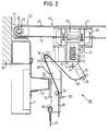
- FIG. 1 shows a door 10 with a rigid, tiltable door leaf 11 in this example and a frame 14 which is an integral part of the building. Furthermore, a lintel 15, the ceiling 16 and rear wall 17 of a garage are shown. A deflection device 20 is attached to the lintel 15 directly above the frame 14. A drive unit 30, which has a housing 31, is fastened to the rear wall 17 with two mounting brackets 32, 33.
- a tension member 40 consisting of a roller shutter belt runs around the deflection device 20 and drive 30 and has a lower run 41 and an upper run 42.
- a switching piece 43 is fastened to the lower run 41 and a switching piece 44 is fastened to the upper run 42.
- a driver 50 is fastened to the lower run 41 of the tension member 40 (FIGS. 2 and 3).
- the lower run 41 is connected by an intermediate member 60 to an upper edge of the door leaf 11.
- the intermediate member 60 has a guide part 70 and a lever part 80.
- the deflection device 20 has a holding bracket 21 and this in turn has an axis 22 on which a rotating roller 23 is rotatably mounted.
- the guide part 70 has a guide housing 71 which surrounds the driver 50.
- a catch 72 is slidably mounted, which engages in a circumferential groove 55 of the driver 50.
- the catch 72 is by a spring 77, in the example shown a helical compression spring, which is located in a cutout 73 of the catch 72 and is at its lower end to the guide housing 71 and at its upper end to the edge of the cutout 73 of the catch 72 supports, loaded upwards.
- An unlocking lever 75 is connected to the catch 72 by an axis 74. A straight end section of the unlocking lever 75 is supported on an area of the guide housing 71.
- a pull cable 90 leads through a bore 78 in the unlocking lever 75 to a lock (not shown) for locking the door leaf 11.
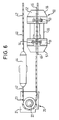
- the guide part 70 has an axis 79 which engages in an elongated hole 83 of the lever part 80.
- the lever part 80 is designed as a two-armed lever 81, whose upper lever arm 82 ends in the elongated hole 83.
- the lower lever arm 85 has a pin 86, around which a loop of a connecting element 91, which is designed as a traction cable, is placed.
- the connecting element 91 extends from the pin 86 to the aforementioned lock of the door leaf 11.
- the lever 81 is pivotably mounted with an axis 84 at an angle 13. The angle 13 is firmly connected to a profile 12 of the door leaf 11.
- the tension member 40 being designed as a rope.
- the contact piece 44 can actuate a switch 34, which is designed here as a micro push-button switch and is fastened in the housing 31.
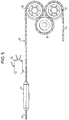
- the tension member 40 is guided via a first auxiliary wheel 36, a drive wheel 35 and a second auxiliary wheel 37.
- the wheels 35, 36 and 37 are gear wheels. They are arranged in a cloverleaf shape.
- the drive wheel 35 engages with its teeth 39 in the auxiliary wheels 36 and 37, but these do not mesh with one another.
- the teeth 39 have a central groove 38 which guides the tension member 40, but which is only so deep that the teeth 39 press into the tension member 40, thus forming a positive connection with it .
- the tension member 40 wraps around the auxiliary wheels 36, 37 to more than 180 ° and, because of the arrangement of the wheels 35, 36, 37 approximately at the corners of an equilateral triangle, the drive wheel 35 approximately to 300 °.
- the driver 50 is dumbbell-shaped and has two substantially identical halves 51 and 52, which are connected to one another by screws 53 and 54. It has a circumferential channel 55 with steep side walls, which here has an essentially rectangular cross section. The sides 56 and 57 of the driver 50 are beveled conically. According to FIG. 3, the driver 50 has an eyelet 58 and 59 on each side. A holding fork 47 of the tension member 40 engages in the eyelet 58.
- the tension member 40 again consists of a roller shutter belt, the ends 45 and 46 of which overlap.
- the two halves of the driver 50 are placed on the tension member 40 in the overlap area.
- the tension member 40 is securely joined to form an endless band.
- the gear wheels 35, 36, 37 do not differ from those shown in FIG. However, you do not need to have groove 38. Lateral flanges or the like are provided, by which it is ensured that the tension member 40 does not slip off the gear wheels 35, 36, 37.
- an electric motor belonging to the drive device 30 is put into operation by a switch or a remote control so that it drives the drive wheel 35 in a clockwise direction.
- the driver 50 is moved to the right in FIG. Since the catch 72 engages in the circumferential groove 55 of the driver 50, the guide part 70 also moves to the right.
- the lever 81 is first pivoted clockwise from the vertical position shown in FIG. As a result, tension is exerted on the connecting element 91, and thus the lock of the door leaf 11 is unlocked.
- the door leaf 11 is the further movement of the driver 50 pivoted clockwise to an open position.
- the switch 44 is attached to the upper run 42 so that it operates the switch 34 when the door leaf 11 has reached its open position. The electric motor is then stopped.
- the electric motor is set in motion in the opposite direction to when it was opened.
- the driver 50 then moves to the left in FIG. 1 and first pivots the door leaf 11 counterclockwise until the door leaf 11 assumes a vertical position.
- the tilted lever 81 is also returned counterclockwise to its vertical starting position.
- the tension on the connecting element 91 is released so that the lock of the door leaf 11 can snap into place and block the door leaf 11.
- the switching piece 43 is attached to the lower run 41 so that it actuates a switch (not shown) when both the gate 11 and the lever 81 have assumed a vertical position.
- the electric motor is then stopped.
- the guide housing 71 slides along the lower run 41 towards the driver 50. Because of the bevelled side 56 of the driver 50, the guide housing 71 is pushed into the original position in which it surrounds the driver 50.
- the catch 72 is initially pushed downwards in FIG. 2 by the bevelled side 56 of the driver 50 and the adjoining cylindrical region and snaps when the original arrangement of driver 50 and guide housing 71 is reached, by the action of the spring 77 in the circumferential groove 55 of the driver 50 a.
- the unlocking lever 75 need not be operated. The door leaf 11 can now be opened again automatically by the door drive.
Landscapes
- Power-Operated Mechanisms For Wings (AREA)
- Building Awnings And Sunshades (AREA)
- Gates (AREA)
- Window Of Vehicle (AREA)
- Yarns And Mechanical Finishing Of Yarns Or Ropes (AREA)
- Portable Nailing Machines And Staplers (AREA)
- Control Of Throttle Valves Provided In The Intake System Or In The Exhaust System (AREA)
- Magnetically Actuated Valves (AREA)
- Magnetic Resonance Imaging Apparatus (AREA)
Applications Claiming Priority (2)
| Application Number | Priority Date | Filing Date | Title |
|---|---|---|---|
| DE4433498A DE4433498A1 (de) | 1994-09-20 | 1994-09-20 | Torantrieb |
| DE4433498 | 1994-09-20 |
Publications (2)
| Publication Number | Publication Date |
|---|---|
| EP0703340A1 true EP0703340A1 (fr) | 1996-03-27 |
| EP0703340B1 EP0703340B1 (fr) | 1998-12-16 |
Family
ID=6528698
Family Applications (1)
| Application Number | Title | Priority Date | Filing Date |
|---|---|---|---|
| EP95113776A Expired - Lifetime EP0703340B1 (fr) | 1994-09-20 | 1995-09-01 | Commande de porte |
Country Status (6)
| Country | Link |
|---|---|
| EP (1) | EP0703340B1 (fr) |
| AT (1) | ATE174654T1 (fr) |
| CZ (1) | CZ243695A3 (fr) |
| DE (2) | DE4433498A1 (fr) |
| HU (1) | HUT73262A (fr) |
| PL (1) | PL310305A1 (fr) |
Cited By (2)
| Publication number | Priority date | Publication date | Assignee | Title |
|---|---|---|---|---|
| US5599529A (en) * | 1987-05-30 | 1997-02-04 | Tioxide Group Plc | Dispersions |
| US20240418024A1 (en) * | 2021-10-21 | 2024-12-19 | Seysen GmbH & Co. KG | Emergency Opening Device for a Lifting Door, Lifting Door and Method for Opening a Lifting Door with an Emergency Opening Device |
Families Citing this family (1)
| Publication number | Priority date | Publication date | Assignee | Title |
|---|---|---|---|---|
| DE102005002102B4 (de) * | 2005-01-14 | 2008-12-11 | Geze Gmbh | Verriegelungsvorrichtung |
Citations (6)
| Publication number | Priority date | Publication date | Assignee | Title |
|---|---|---|---|---|
| US2909718A (en) * | 1955-08-26 | 1959-10-20 | Julius J Lawick | Door operating apparatus |
| US3066729A (en) * | 1958-04-14 | 1962-12-04 | Glenn P Gessell | Overhead door operator with safety disconnectible coupling |
| US3164761A (en) * | 1959-10-20 | 1965-01-05 | Moscow K Richmond | Load-responsive, automatic-stop drive mechanism |
| DE2117325A1 (de) * | 1971-04-08 | 1972-10-26 | Griebel Electronic KG, 8720 Schweinfurt | Kipptorantrieb |
| GB1480733A (en) * | 1974-07-12 | 1977-07-20 | King W | Apparatus for use in opening doors |
| DE7729336U1 (de) | 1977-09-22 | 1978-02-23 | Berner, Kurt, 7403 Ammerbuch | Antriebsvorrichtung fuer kipptore, insbesondere garagentore |
-
1994
- 1994-09-20 DE DE4433498A patent/DE4433498A1/de not_active Withdrawn
-
1995
- 1995-09-01 AT AT95113776T patent/ATE174654T1/de not_active IP Right Cessation
- 1995-09-01 DE DE59504544T patent/DE59504544D1/de not_active Expired - Fee Related
- 1995-09-01 EP EP95113776A patent/EP0703340B1/fr not_active Expired - Lifetime
- 1995-09-05 HU HU9502595A patent/HUT73262A/hu unknown
- 1995-09-07 PL PL95310305A patent/PL310305A1/xx unknown
- 1995-09-19 CZ CZ952436A patent/CZ243695A3/cs unknown
Patent Citations (6)
| Publication number | Priority date | Publication date | Assignee | Title |
|---|---|---|---|---|
| US2909718A (en) * | 1955-08-26 | 1959-10-20 | Julius J Lawick | Door operating apparatus |
| US3066729A (en) * | 1958-04-14 | 1962-12-04 | Glenn P Gessell | Overhead door operator with safety disconnectible coupling |
| US3164761A (en) * | 1959-10-20 | 1965-01-05 | Moscow K Richmond | Load-responsive, automatic-stop drive mechanism |
| DE2117325A1 (de) * | 1971-04-08 | 1972-10-26 | Griebel Electronic KG, 8720 Schweinfurt | Kipptorantrieb |
| GB1480733A (en) * | 1974-07-12 | 1977-07-20 | King W | Apparatus for use in opening doors |
| DE7729336U1 (de) | 1977-09-22 | 1978-02-23 | Berner, Kurt, 7403 Ammerbuch | Antriebsvorrichtung fuer kipptore, insbesondere garagentore |
Cited By (3)
| Publication number | Priority date | Publication date | Assignee | Title |
|---|---|---|---|---|
| US5599529A (en) * | 1987-05-30 | 1997-02-04 | Tioxide Group Plc | Dispersions |
| US20240418024A1 (en) * | 2021-10-21 | 2024-12-19 | Seysen GmbH & Co. KG | Emergency Opening Device for a Lifting Door, Lifting Door and Method for Opening a Lifting Door with an Emergency Opening Device |
| US12560025B2 (en) * | 2021-10-21 | 2026-02-24 | Seysen GmbH & Co. KG | Emergency opening device for a lifting gate assembly, lifting gate assembly and method for opening a lifting gate assembly with an emergency opening device |
Also Published As
| Publication number | Publication date |
|---|---|
| HUT73262A (en) | 1996-07-29 |
| DE4433498A1 (de) | 1996-03-21 |
| CZ243695A3 (en) | 1996-04-17 |
| DE59504544D1 (de) | 1999-01-28 |
| HU9502595D0 (en) | 1995-10-30 |
| PL310305A1 (en) | 1996-04-01 |
| ATE174654T1 (de) | 1999-01-15 |
| EP0703340B1 (fr) | 1998-12-16 |
Similar Documents
| Publication | Publication Date | Title |
|---|---|---|
| EP0040800B1 (fr) | Volet roulant | |
| DE2947501A1 (de) | Ein- und ausfahrbare abdeckvorrichtung, insbesondere rolladen fuer fenster, tueren, tore o.dgl. | |
| EP1223299B1 (fr) | Store enroulable, en particulier moustiquaire | |
| DE3415551C2 (de) | Rolladen für Dachfenster | |
| EP0128391B1 (fr) | Porte à coulisses mobile sur un arc | |
| DE1559775B1 (de) | Vorrichtung zum OEffnen und Schliessen von Fenstern od.dgl. | |
| DE112005001745T5 (de) | Toröffner | |
| CH635164A5 (de) | Raffstore. | |
| DE202008001121U1 (de) | Tor, insbesondere Sektionaltor, und Torantrieb | |
| EP0703340B1 (fr) | Commande de porte | |
| WO2006136129A1 (fr) | Mecanisme de commande de porte a chaine pousseuse ou rigide | |
| DE19655108B4 (de) | Rolladen für Fenster, Türen oder dergleichen | |
| EP1128015A2 (fr) | Fenêtre ou porte à coulissement parallèle | |
| AT407067B (de) | Antriebseinrichtung für einen schiebeflügel | |
| DE2815997A1 (de) | Motorisch betaetigtes garagentor | |
| AT397277B (de) | Motorischer torantrieb für ein garagentor | |
| WO2022002537A1 (fr) | Système de fermeture, en particulier pour des meubles de type armoire | |
| DE3105091A1 (de) | "antriebsvorrichtung fuer ein tor" | |
| DE2228783A1 (de) | Gelenk-deckentor sowie gebaeude, garagenbox oder dgl. mit einem solchen tor | |
| DE19646199A1 (de) | Schwenk-, insbesondere Falttor | |
| DE2523711B2 (de) | Betaetigungsvorrichtung fuer fenster | |
| DE2619737A1 (de) | Lamellenpanzertor, insbesondere garagentor | |
| WO2003029588A1 (fr) | Armoire de distribution | |
| DE1559775C (de) | Vorrichtung zum öffnen und Schließen von Fenstern od.dgl | |
| DE8115473U1 (de) | Gliederhubtor |
Legal Events
| Date | Code | Title | Description |
|---|---|---|---|
| PUAI | Public reference made under article 153(3) epc to a published international application that has entered the european phase |
Free format text: ORIGINAL CODE: 0009012 |
|
| AK | Designated contracting states |
Kind code of ref document: A1 Designated state(s): AT DE ES FR GB GR IT |
|
| RAX | Requested extension states of the european patent have changed |
Free format text: SI PAYMENT 950901 |
|
| 17P | Request for examination filed |
Effective date: 19960422 |
|
| GRAG | Despatch of communication of intention to grant |
Free format text: ORIGINAL CODE: EPIDOS AGRA |
|
| 17Q | First examination report despatched |
Effective date: 19971028 |
|
| GRAG | Despatch of communication of intention to grant |
Free format text: ORIGINAL CODE: EPIDOS AGRA |
|
| GRAH | Despatch of communication of intention to grant a patent |
Free format text: ORIGINAL CODE: EPIDOS IGRA |
|
| GRAH | Despatch of communication of intention to grant a patent |
Free format text: ORIGINAL CODE: EPIDOS IGRA |
|
| GRAA | (expected) grant |
Free format text: ORIGINAL CODE: 0009210 |
|
| AK | Designated contracting states |
Kind code of ref document: B1 Designated state(s): AT DE ES FR GB GR IT |
|
| AX | Request for extension of the european patent |
Free format text: SI PAYMENT 950901 |
|
| PG25 | Lapsed in a contracting state [announced via postgrant information from national office to epo] |
Ref country code: IT Free format text: LAPSE BECAUSE OF FAILURE TO SUBMIT A TRANSLATION OF THE DESCRIPTION OR TO PAY THE FEE WITHIN THE PRE;WARNING: LAPSES OF ITALIAN PATENTS WITH EFFECTIVE DATE BEFORE 2007 MAY HAVE OCCURRED AT ANY TIME BEFORE 2007. THE CORRECT EFFECTIVE DATE MAY BE DIFFERENT FROM THE ONE RECORDED.SCRIBED TIME-LIMIT Effective date: 19981216 Ref country code: GR Free format text: LAPSE BECAUSE OF NON-PAYMENT OF DUE FEES Effective date: 19981216 Ref country code: GB Free format text: LAPSE BECAUSE OF NON-PAYMENT OF DUE FEES Effective date: 19981216 Ref country code: FR Free format text: LAPSE BECAUSE OF FAILURE TO SUBMIT A TRANSLATION OF THE DESCRIPTION OR TO PAY THE FEE WITHIN THE PRESCRIBED TIME-LIMIT Effective date: 19981216 Ref country code: ES Free format text: THE PATENT HAS BEEN ANNULLED BY A DECISION OF A NATIONAL AUTHORITY Effective date: 19981216 |
|
| REF | Corresponds to: |
Ref document number: 174654 Country of ref document: AT Date of ref document: 19990115 Kind code of ref document: T |
|
| REF | Corresponds to: |
Ref document number: 59504544 Country of ref document: DE Date of ref document: 19990128 |
|
| EN | Fr: translation not filed | ||
| GBV | Gb: ep patent (uk) treated as always having been void in accordance with gb section 77(7)/1977 [no translation filed] |
Effective date: 19981216 |
|
| PGFP | Annual fee paid to national office [announced via postgrant information from national office to epo] |
Ref country code: AT Payment date: 19990723 Year of fee payment: 5 |
|
| PGFP | Annual fee paid to national office [announced via postgrant information from national office to epo] |
Ref country code: DE Payment date: 19990924 Year of fee payment: 5 |
|
| PLBE | No opposition filed within time limit |
Free format text: ORIGINAL CODE: 0009261 |
|
| STAA | Information on the status of an ep patent application or granted ep patent |
Free format text: STATUS: NO OPPOSITION FILED WITHIN TIME LIMIT |
|
| 26N | No opposition filed | ||
| PG25 | Lapsed in a contracting state [announced via postgrant information from national office to epo] |
Ref country code: AT Free format text: LAPSE BECAUSE OF NON-PAYMENT OF DUE FEES Effective date: 20000901 |
|
| PG25 | Lapsed in a contracting state [announced via postgrant information from national office to epo] |
Ref country code: DE Free format text: LAPSE BECAUSE OF NON-PAYMENT OF DUE FEES Effective date: 20010601 |