EP0703349B1 - Méthode et dispositif pour diagraphier des puits non-circulaires - Google Patents
Méthode et dispositif pour diagraphier des puits non-circulaires Download PDFInfo
- Publication number
- EP0703349B1 EP0703349B1 EP94402116A EP94402116A EP0703349B1 EP 0703349 B1 EP0703349 B1 EP 0703349B1 EP 94402116 A EP94402116 A EP 94402116A EP 94402116 A EP94402116 A EP 94402116A EP 0703349 B1 EP0703349 B1 EP 0703349B1
- Authority
- EP
- European Patent Office
- Prior art keywords
- borehole
- pad
- sonde
- wall
- logging
- Prior art date
- Legal status (The legal status is an assumption and is not a legal conclusion. Google has not performed a legal analysis and makes no representation as to the accuracy of the status listed.)
- Expired - Lifetime
Links
Images
Classifications
-
- E—FIXED CONSTRUCTIONS
- E21—EARTH OR ROCK DRILLING; MINING
- E21B—EARTH OR ROCK DRILLING; OBTAINING OIL, GAS, WATER, SOLUBLE OR MELTABLE MATERIALS OR A SLURRY OF MINERALS FROM WELLS
- E21B49/00—Testing the nature of borehole walls; Formation testing; Methods or apparatus for obtaining samples of soil or well fluids, specially adapted to earth drilling or wells
Definitions
- the invention relates to the logging of subsurface formations traversed by a borehole, by means of logging sondes displaced along the borehole and equipped with a sensor-carrying pad urged into contact with the borehole wall. More specifically, the invention relates to a logging technique adapted for use in stressed boreholes.
- Tectonic stress is known to cause borehole breakout along the direction of least horizontal stress.
- the borehole has a larger dimension ("long axis") in the direction of breakout than in the perpendicular direction ("short axis").
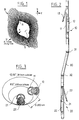
- a borehole with breakout is exemplified on figure 1, which is an ultrasonic image of a 20 centimeters high section of the borehole, shown as if seen from above.
- figure 1 is an ultrasonic image of a 20 centimeters high section of the borehole, shown as if seen from above.
- This example shows that the shape of the borehole cross-section may be quite irregular, and far indeed from a pure geometrical figure such as an ellipsis or an oval. For that reason, such boreholes shall simply be referred to hereinafter as "non-circular".
- a technique known as "short-axis logging" has been implemented as an attempt to obtain good quality logs in non-circular boreholes.
- the purpose is to ensure contact of the pad with the borehole wall in its "short axis" regions, which, as shown on figure 1, are smoother and more susceptible to provide good contact with the pad than the "long axis regions".
- the sonde In order to align the pad with the "short axis", the sonde is equipped with extra springs, arranged so that the potential energy of the total spring system is minimized when the sonde is aligned along the "short axis".
- Figure 1 illustrates the effect of tectonic stress on the geometry of a borehole.
- the breakout axis is indicated at B. It is apparent on figure 1 that while the cross-section of the borehole can be roughly depicted as a "flattened circle", and a "long axis" (substantially aligned with the breakout axis) and a “short axis” can be identified, the cross-section of the borehole is asymmetrical and irregular, and the rugosity of the borehole wall shows wide variations.
- the borehole wall is extremely rugose in the breakout regions R, R', while it is smooth in the "short axis" region along generatrix S-S'.
- Figure 2 shows an embodiment of a logging tool string according to the invention.
- the string includes gamma ray density tools, namely Schlumberger's Litho-Density Tool (LDT).
- LDT Litho-Density Tool
- the invention is not limited to a particular type of logging tool and applies to all kinds of logging tools which include a sensor-carrying pad adapted for engagement with the wall of the borehole.
- Schlumberger's MSFL a microresistivity logging tool.
- the logging tool string of figure 1 is suspended from a logging cable connected to a surface equipment, with a telemetry unit provided between the tool string and the cable.
- a telemetry unit provided between the tool string and the cable.
- the tools shown in figure 2 may be used in conjunction with logging tools of other types such as a resistivity tools (induction or Laterolog), a neutron logging tool, etc.
- the string comprises a pair of logging tools, an upper tool 10 and a lower tool 20, which are preferably identical.
- Each tool includes an elongate body resp. 11, 21.
- a pad resp. 12, 22 carrying a gamma ray source and gamma ray detectors is mounted on one side of the body. The pad is movable between a retracted position and a deployed position.
- a spring-loaded arm resp. 13, 23 is provided on the side of the body in diametrical opposition (with respect to the tool axis) to the pad. The arm resp. 13, 23 is held retracted during the descent of the tool string and once the string has reached the bottom of the section to be logged, the arm is released and urged by its spring into engagement with the borehole wall.
- the tools 10, 20 are connected by a spacer sub 30 which prevents vents trains relative rotation between the tools and the tools to remain 90° apart in azimuth.
- the respective symmetry planes of pads 12, 22 are always perpendicular, as shown in figure 3. This may be achieved by providing respective key and slot arrangements (not shown) at the connections between the spacer sub 30 and the tools 10, 20, thus securing angularly the tools to the spacer sub, with a 90° spacing between the azimuthal positions of the key slots.
- the tools 10, 20 may have their axes offset, in order for the pads to be normal to, and firmly pressed against the borehole wall in various borehole diameters and geometries, as shown in figure 3.
- knuckle joints 31, 32 are provided for connecting the spacer sub and the respective tools 10, 20. Knuckle joints, as shown in figure 2, enable spacer sub 30 to tilt in any direction with respect to the respective tool, without allowing relative rotation. Typically, the maximum tilt angle provided by knuckle joints is 4°. It is to be noted that the fitness to various borehole dimensions/geometries is enhanced by the ability to move the pads with respect to the tool body, as illustrated in figure 3.
- the performance of a logging operation with a tool string such as shown in figure 2 requires the simultaneous acquisition of the measurement data produced by the tools, so as to produce two logs of the same property, for instance, formation density, in the same section of the borehole.
Landscapes
- Life Sciences & Earth Sciences (AREA)
- Engineering & Computer Science (AREA)
- Geology (AREA)
- Mining & Mineral Resources (AREA)
- Physics & Mathematics (AREA)
- Environmental & Geological Engineering (AREA)
- Fluid Mechanics (AREA)
- General Life Sciences & Earth Sciences (AREA)
- Geochemistry & Mineralogy (AREA)
- Geophysics And Detection Of Objects (AREA)
Claims (5)
- Procédé de diagraphie destiné à une utilisation dans des trous de forage non circulaires, comprenant les étapes consistant à :établir une première diagraphie, relative à une propriété des formations traversées par le trou de forage, au moyen d'une première sonde (10) ayant au moins un capteur porté par une cale de support (12) maintenue en contact avec la paroi du trou de forage,établir simultanément une seconde diagraphie, relative à la même propriété, au moyen d'une seconde sonde (20) ayant au moins un capteur porté par une cale de support (22) maintenue en contact avec la paroi du trou de forage, les cales de support desdites première et seconde sondes étant maintenues orientées avec une différence azimutale de 90° entre elles.
- Procédé de diagraphie destiné à une utilisation dans des trous de forage non circulaires, comprenant les étapes consistant à :déplacer, le long de la paroi d'un trou de forage, une première cale de support (12) portant au moins un capteur pour obtenir une diagraphie relative à une propriété des formations traversées par le trou de forage,déplacer simultanément, le long de la paroi d'un trou de forage, à une certaine distance de ladite première cale de support (12) dans le sens longitudinal du trou de forage, une seconde cale de support (22) portant au moins un capteur pour obtenir une seconde diagraphie relative à la même propriété, en maintenant lesdites cales de support orientées avec un espacement azimutal de 90° entre elles.
- Dispositif de diagraphie destiné à une utilisation dans des trous de forage non circulaires, comprenant :une première (10) et une seconde (20) sondes décalées longitudinalement l'une par rapport à l'autre, chaque sonde comportant : une cale de support (12, 22) prévue pour être en contact avec la paroi du trou de forage, au moins un capteur sur chaque sonde, et des moyens (13, 23) pour maintenir la cale de support contre la paroi du trou de forage,lesdites première et seconde sondes produisant des mesures relatives à la même propriété des formations, etun moyen (30) pour relier les première et seconde sondes de manière à maintenir les cales de support orientées avec un espacement azimutal de 90° entre elles.
- Dispositif selon la revendication 3, dans lequel ledit moyen de connexion permet aux sondes de se décaler l'une par rapport à l'autre.
- Dispositif selon la revendication 4, dans lequel ledit moyen de connexion comprend un joint à rotule (31, 32) à chacune de ses extrémités.
Priority Applications (3)
| Application Number | Priority Date | Filing Date | Title |
|---|---|---|---|
| DE69417031T DE69417031D1 (de) | 1994-09-23 | 1994-09-23 | Verfahren und Vorrichtung für Bohrlochmessungen in unrunden Bohrlöchern |
| EP94402116A EP0703349B1 (fr) | 1994-09-23 | 1994-09-23 | Méthode et dispositif pour diagraphier des puits non-circulaires |
| US08/532,207 US6065218A (en) | 1994-09-23 | 1995-09-22 | Method and apparatus for logging non-circular boreholes |
Applications Claiming Priority (1)
| Application Number | Priority Date | Filing Date | Title |
|---|---|---|---|
| EP94402116A EP0703349B1 (fr) | 1994-09-23 | 1994-09-23 | Méthode et dispositif pour diagraphier des puits non-circulaires |
Publications (2)
| Publication Number | Publication Date |
|---|---|
| EP0703349A1 EP0703349A1 (fr) | 1996-03-27 |
| EP0703349B1 true EP0703349B1 (fr) | 1999-03-10 |
Family
ID=8218038
Family Applications (1)
| Application Number | Title | Priority Date | Filing Date |
|---|---|---|---|
| EP94402116A Expired - Lifetime EP0703349B1 (fr) | 1994-09-23 | 1994-09-23 | Méthode et dispositif pour diagraphier des puits non-circulaires |
Country Status (3)
| Country | Link |
|---|---|
| US (1) | US6065218A (fr) |
| EP (1) | EP0703349B1 (fr) |
| DE (1) | DE69417031D1 (fr) |
Families Citing this family (18)
| Publication number | Priority date | Publication date | Assignee | Title |
|---|---|---|---|---|
| US6188961B1 (en) | 1999-03-31 | 2001-02-13 | Hilliburton Energy Services, Inc. | Acoustic logging apparatus and method |
| US6748329B2 (en) | 2000-12-08 | 2004-06-08 | Halliburton Energy Services, Inc. | Acoustic signal processing method using array coherency |
| GB0102900D0 (en) * | 2001-02-06 | 2001-03-21 | Smart Stabiliser Systems Ltd | Surveying of boreholes |
| US6854192B2 (en) * | 2001-02-06 | 2005-02-15 | Smart Stabilizer Systems Limited | Surveying of boreholes |
| CA2443217C (fr) * | 2001-04-02 | 2009-12-22 | Tokyo Gas Co., Ltd. | Methode et dispositif de mesure du diametre interieur d'une canalisation |
| CA2415921C (fr) * | 2002-01-14 | 2013-11-26 | Computalog Usa Inc. | Methode et appareil d'imagerie de la resistivite avec deport total pour utilisation dans les puits de forage |
| GB0221753D0 (en) * | 2002-09-19 | 2002-10-30 | Smart Stabilizer Systems Ltd | Borehole surveying |
| CA2547191A1 (fr) * | 2003-12-05 | 2005-06-23 | Exxonmobil Research And Engineering Company | Performances superieures d'extraction obtenues par l'utilisation d'acide sulfurique |
| US7347003B2 (en) * | 2004-12-06 | 2008-03-25 | Clemson University | Device to measure axial displacement in a borehole |
| US7339161B2 (en) | 2005-02-24 | 2008-03-04 | Schlumberger Technology Corporation | Shielded pads for detecting subsurface radiation phenomena |
| US7436185B2 (en) * | 2005-06-27 | 2008-10-14 | Schlumberger Technology Corporation | Highly integrated logging tool |
| US20060290353A1 (en) * | 2005-06-27 | 2006-12-28 | Schlumberger Technology Corporation | Pad assembly for logging tool |
| US8446150B2 (en) * | 2008-06-06 | 2013-05-21 | Halliburton Energy Services, Inc. | Apparatus and method for logging in boreholes with a non-circular section |
| US7954252B2 (en) * | 2008-06-06 | 2011-06-07 | Schlumberger Technology Corporation | Methods and apparatus to determine and use wellbore diameters |
| GB2484499B8 (en) * | 2010-10-13 | 2014-11-12 | Reeves Wireline Tech Ltd | Apparatus and methods for orienting, stabilising or stably operating a logging tool |
| CA2906559A1 (fr) * | 2013-03-14 | 2014-10-02 | Schlumberger Canada Limited | Outil pour mesurer une geometrie de puits de forage |
| US10443995B2 (en) * | 2015-09-16 | 2019-10-15 | Shane S. Turay | Device for inspecting and measuring sewer/utility structures |
| CN115854987B (zh) * | 2023-02-14 | 2023-05-26 | 中国铁道科学研究院集团有限公司铁道建筑研究所 | 一种可回收测斜装置 |
Family Cites Families (12)
| Publication number | Priority date | Publication date | Assignee | Title |
|---|---|---|---|---|
| US2846190A (en) * | 1952-02-29 | 1958-08-05 | Schlumberger Well Surv Corp | Hydraulic devices |
| US2864173A (en) * | 1955-03-08 | 1958-12-16 | Perforating Guns Atlas Corp | Electrical well caliper tool |
| US3648515A (en) * | 1969-10-29 | 1972-03-14 | Dresser Ind | Radioactivity logging apparatus having shielded wall contacting source and detector |
| US3772794A (en) * | 1971-12-22 | 1973-11-20 | Hercules Inc | Borehole measuring device |
| US4506219A (en) * | 1982-07-30 | 1985-03-19 | Schlumberger Technology Corporation | Borehole tool outrigger arm displacement control mechanism |
| FR2545872B1 (fr) * | 1983-05-10 | 1985-07-26 | Schlumberger Prospection | Appareil de centrage d'un outil dans un puits tube en particulier pour puits devie |
| US4665511A (en) * | 1984-03-30 | 1987-05-12 | Nl Industries, Inc. | System for acoustic caliper measurements |
| DE3611374C1 (en) * | 1986-04-03 | 1987-08-20 | Prakla Seismos Ag | Chain-shaped arrangement of several borehole probes |
| US5101104A (en) * | 1990-09-27 | 1992-03-31 | Western Atlas International, Inc. | Carrier apparatus for radioactive well logging instrument |
| FR2685139B1 (fr) * | 1991-12-11 | 1994-05-20 | Institut Francais Petrole | Procede et dispositif pour l'interconnexion electrique d'appareils tels que des outils de puits. |
| FR2700806B1 (fr) * | 1993-01-27 | 1995-03-17 | Elf Aquitaine | Procédé de détermination des variations de la morphologie d'un puits de forage. |
| CA2141086A1 (fr) * | 1995-01-25 | 1996-07-26 | Gerhard Herget | Extensometre de contrainte rocheuse |
-
1994
- 1994-09-23 DE DE69417031T patent/DE69417031D1/de not_active Expired - Lifetime
- 1994-09-23 EP EP94402116A patent/EP0703349B1/fr not_active Expired - Lifetime
-
1995
- 1995-09-22 US US08/532,207 patent/US6065218A/en not_active Expired - Lifetime
Also Published As
| Publication number | Publication date |
|---|---|
| US6065218A (en) | 2000-05-23 |
| EP0703349A1 (fr) | 1996-03-27 |
| DE69417031D1 (de) | 1999-04-15 |
Similar Documents
| Publication | Publication Date | Title |
|---|---|---|
| EP0703349B1 (fr) | Méthode et dispositif pour diagraphier des puits non-circulaires | |
| US7394257B2 (en) | Modular downhole tool system | |
| US7913773B2 (en) | Bidirectional drill string telemetry for measuring and drilling control | |
| US4360777A (en) | Induction dipmeter apparatus and method | |
| US7265649B1 (en) | Flexible inductive resistivity device | |
| AU754910B2 (en) | Method and apparatus for directional well logging | |
| CA2411566C (fr) | Tube modifie equipe d'un doublet magnetique incline ou transversal pour la diagraphie | |
| US6600321B2 (en) | Apparatus and method for wellbore resistivity determination and imaging using capacitive coupling | |
| US7398837B2 (en) | Drill bit assembly with a logging device | |
| EP2108982B1 (fr) | Outil de mesure de résistivité au moyen d'ondes électromagnétiques, muni d'une antenne inclinée | |
| EP1344091B1 (fr) | Capteurs de diagraphie en cours de forage montes sur des nervures | |
| CA2132787C (fr) | Dispositif de diagraphie combine | |
| US20080230273A1 (en) | Instantaneous measurement of drillstring orientation | |
| EP0366567A3 (fr) | Outil combiné pour fond de puits | |
| GB2369890A (en) | Electromagnetic induction well logging | |
| CN1009967B (zh) | 井眼地震波接收器 | |
| CN101253304A (zh) | 用于测量和钻探控制的双向钻柱遥测技术 | |
| NO348441B1 (en) | Dedicated wireways for collar-mounted bobbin antennas | |
| EP0672818B1 (fr) | Ensemble détecteur modulaire de mesure pendant le forage | |
| US20070193776A1 (en) | Borehole tool | |
| AU2007248310B2 (en) | Drill bit assembly with a logging device | |
| US5596142A (en) | Well logging apparatus comprising a measuring pad and a combinaton device including such apparatus | |
| US12173564B2 (en) | Telemetry tool joint | |
| AU685832B2 (en) | A well logging device with a pad | |
| US4069591A (en) | Elastomeric inclinometer |
Legal Events
| Date | Code | Title | Description |
|---|---|---|---|
| PUAI | Public reference made under article 153(3) epc to a published international application that has entered the european phase |
Free format text: ORIGINAL CODE: 0009012 |
|
| AK | Designated contracting states |
Kind code of ref document: A1 Designated state(s): DE DK FR GB IT NL |
|
| 17P | Request for examination filed |
Effective date: 19960913 |
|
| GRAG | Despatch of communication of intention to grant |
Free format text: ORIGINAL CODE: EPIDOS AGRA |
|
| 17Q | First examination report despatched |
Effective date: 19980422 |
|
| GRAG | Despatch of communication of intention to grant |
Free format text: ORIGINAL CODE: EPIDOS AGRA |
|
| GRAH | Despatch of communication of intention to grant a patent |
Free format text: ORIGINAL CODE: EPIDOS IGRA |
|
| GRAH | Despatch of communication of intention to grant a patent |
Free format text: ORIGINAL CODE: EPIDOS IGRA |
|
| GRAA | (expected) grant |
Free format text: ORIGINAL CODE: 0009210 |
|
| AK | Designated contracting states |
Kind code of ref document: B1 Designated state(s): DE DK FR GB IT NL |
|
| PG25 | Lapsed in a contracting state [announced via postgrant information from national office to epo] |
Ref country code: NL Free format text: LAPSE BECAUSE OF FAILURE TO SUBMIT A TRANSLATION OF THE DESCRIPTION OR TO PAY THE FEE WITHIN THE PRESCRIBED TIME-LIMIT Effective date: 19990310 Ref country code: IT Free format text: LAPSE BECAUSE OF FAILURE TO SUBMIT A TRANSLATION OF THE DESCRIPTION OR TO PAY THE FEE WITHIN THE PRE;WARNING: LAPSES OF ITALIAN PATENTS WITH EFFECTIVE DATE BEFORE 2007 MAY HAVE OCCURRED AT ANY TIME BEFORE 2007. THE CORRECT EFFECTIVE DATE MAY BE DIFFERENT FROM THE ONE RECORDED.SCRIBED TIME-LIMIT Effective date: 19990310 Ref country code: FR Free format text: LAPSE BECAUSE OF FAILURE TO SUBMIT A TRANSLATION OF THE DESCRIPTION OR TO PAY THE FEE WITHIN THE PRESCRIBED TIME-LIMIT Effective date: 19990310 |
|
| REF | Corresponds to: |
Ref document number: 69417031 Country of ref document: DE Date of ref document: 19990415 |
|
| PG25 | Lapsed in a contracting state [announced via postgrant information from national office to epo] |
Ref country code: DK Free format text: LAPSE BECAUSE OF FAILURE TO SUBMIT A TRANSLATION OF THE DESCRIPTION OR TO PAY THE FEE WITHIN THE PRESCRIBED TIME-LIMIT Effective date: 19990610 |
|
| PG25 | Lapsed in a contracting state [announced via postgrant information from national office to epo] |
Ref country code: DE Free format text: LAPSE BECAUSE OF FAILURE TO SUBMIT A TRANSLATION OF THE DESCRIPTION OR TO PAY THE FEE WITHIN THE PRESCRIBED TIME-LIMIT Effective date: 19990611 |
|
| NLV1 | Nl: lapsed or annulled due to failure to fulfill the requirements of art. 29p and 29m of the patents act | ||
| EN | Fr: translation not filed | ||
| PLBE | No opposition filed within time limit |
Free format text: ORIGINAL CODE: 0009261 |
|
| STAA | Information on the status of an ep patent application or granted ep patent |
Free format text: STATUS: NO OPPOSITION FILED WITHIN TIME LIMIT |
|
| 26N | No opposition filed | ||
| REG | Reference to a national code |
Ref country code: GB Ref legal event code: IF02 |
|
| PGFP | Annual fee paid to national office [announced via postgrant information from national office to epo] |
Ref country code: GB Payment date: 20130918 Year of fee payment: 20 |
|
| REG | Reference to a national code |
Ref country code: GB Ref legal event code: PE20 Expiry date: 20140922 |
|
| PG25 | Lapsed in a contracting state [announced via postgrant information from national office to epo] |
Ref country code: GB Free format text: LAPSE BECAUSE OF EXPIRATION OF PROTECTION Effective date: 20140922 |