EP0703355B1 - Brennkraftmaschine - Google Patents
Brennkraftmaschine Download PDFInfo
- Publication number
- EP0703355B1 EP0703355B1 EP95114970A EP95114970A EP0703355B1 EP 0703355 B1 EP0703355 B1 EP 0703355B1 EP 95114970 A EP95114970 A EP 95114970A EP 95114970 A EP95114970 A EP 95114970A EP 0703355 B1 EP0703355 B1 EP 0703355B1
- Authority
- EP
- European Patent Office
- Prior art keywords
- valve
- intake
- combustion engine
- engine
- internal combustion
- Prior art date
- Legal status (The legal status is an assumption and is not a legal conclusion. Google has not performed a legal analysis and makes no representation as to the accuracy of the status listed.)
- Expired - Lifetime
Links
- 238000002485 combustion reaction Methods 0.000 title claims description 35
- 230000006698 induction Effects 0.000 claims description 27
- 230000000694 effects Effects 0.000 claims description 13
- 238000011144 upstream manufacturing Methods 0.000 claims description 11
- 239000000446 fuel Substances 0.000 claims description 9
- 230000003111 delayed effect Effects 0.000 claims description 3
- 239000000203 mixture Substances 0.000 claims 2
- 239000007789 gas Substances 0.000 description 10
- 238000009423 ventilation Methods 0.000 description 8
- 230000006835 compression Effects 0.000 description 3
- 238000007906 compression Methods 0.000 description 3
- 238000010276 construction Methods 0.000 description 3
- 238000002347 injection Methods 0.000 description 3
- 239000007924 injection Substances 0.000 description 3
- 235000014676 Phragmites communis Nutrition 0.000 description 1
- 230000002411 adverse Effects 0.000 description 1
- 238000011109 contamination Methods 0.000 description 1
- 238000011217 control strategy Methods 0.000 description 1
- 230000007812 deficiency Effects 0.000 description 1
- 230000002939 deleterious effect Effects 0.000 description 1
- 238000010586 diagram Methods 0.000 description 1
- 238000001914 filtration Methods 0.000 description 1
- 230000030279 gene silencing Effects 0.000 description 1
- 229930195733 hydrocarbon Natural products 0.000 description 1
- 150000002430 hydrocarbons Chemical class 0.000 description 1
Images


Classifications
-
- F—MECHANICAL ENGINEERING; LIGHTING; HEATING; WEAPONS; BLASTING
- F02—COMBUSTION ENGINES; HOT-GAS OR COMBUSTION-PRODUCT ENGINE PLANTS
- F02M—SUPPLYING COMBUSTION ENGINES IN GENERAL WITH COMBUSTIBLE MIXTURES OR CONSTITUENTS THEREOF
- F02M25/00—Engine-pertinent apparatus for adding non-fuel substances or small quantities of secondary fuel to combustion-air, main fuel or fuel-air mixture
- F02M25/06—Engine-pertinent apparatus for adding non-fuel substances or small quantities of secondary fuel to combustion-air, main fuel or fuel-air mixture adding lubricant vapours
-
- F—MECHANICAL ENGINEERING; LIGHTING; HEATING; WEAPONS; BLASTING
- F02—COMBUSTION ENGINES; HOT-GAS OR COMBUSTION-PRODUCT ENGINE PLANTS
- F02B—INTERNAL-COMBUSTION PISTON ENGINES; COMBUSTION ENGINES IN GENERAL
- F02B29/00—Engines characterised by provision for charging or scavenging not provided for in groups F02B25/00, F02B27/00 or F02B33/00 - F02B39/00; Details thereof
- F02B29/02—Other fluid-dynamic features of induction systems for improving quantity of charge
-
- F—MECHANICAL ENGINEERING; LIGHTING; HEATING; WEAPONS; BLASTING
- F02—COMBUSTION ENGINES; HOT-GAS OR COMBUSTION-PRODUCT ENGINE PLANTS
- F02B—INTERNAL-COMBUSTION PISTON ENGINES; COMBUSTION ENGINES IN GENERAL
- F02B75/00—Other engines
- F02B75/02—Engines characterised by their cycles, e.g. six-stroke
- F02B2075/022—Engines characterised by their cycles, e.g. six-stroke having less than six strokes per cycle
- F02B2075/027—Engines characterised by their cycles, e.g. six-stroke having less than six strokes per cycle four
-
- Y—GENERAL TAGGING OF NEW TECHNOLOGICAL DEVELOPMENTS; GENERAL TAGGING OF CROSS-SECTIONAL TECHNOLOGIES SPANNING OVER SEVERAL SECTIONS OF THE IPC; TECHNICAL SUBJECTS COVERED BY FORMER USPC CROSS-REFERENCE ART COLLECTIONS [XRACs] AND DIGESTS
- Y02—TECHNOLOGIES OR APPLICATIONS FOR MITIGATION OR ADAPTATION AGAINST CLIMATE CHANGE
- Y02T—CLIMATE CHANGE MITIGATION TECHNOLOGIES RELATED TO TRANSPORTATION
- Y02T10/00—Road transport of goods or passengers
- Y02T10/10—Internal combustion engine [ICE] based vehicles
- Y02T10/12—Improving ICE efficiencies
Definitions
- This invention relates to an internal combustion engine according to the preamble part of claim 1.
- the induction system includes, in addition the normal port control which communicates the intake passage with the combustion chamber, a check valve that is positioned upstream of the port control and which precludes reverse flow through the induction system.
- a check valve that is positioned upstream of the port control and which precludes reverse flow through the induction system.
- This type of arrangement is commonly used in 2-cycle engines, but also may be employed in four-cycle engines to achieve some of the same purposes. That is, in a 2-cycle engine, the port control of the intake port is achieved by the movement of the piston relative to the port.
- the intake port is controlled by a valve that is operated in timed sequence with the engine crankshaft.
- the use of a check valve may provide additional advantages in charging efficiencies because of its ability to preclude reverse flow.
- check valves provide improved induction efficiency under some conditions
- the resistance of the check valve to opening movement can, in some instances, restrict flow.
- inertia in the intake system which must be overcome each time the check valve opens and closes and, thus, the air flow may be delayed from the time when the intake port is actually open.
- An example for such an internal combustion engine is disclosed in the Japanese patent application JP-A-61 200326. This engine uses its crankcase to create a super charging, but still does not solve the problem of reducing delay by offering a way to keep the valve open.
- crankcase compression and ventilation systems it is well known that blow-by crankcase ventilation gases tend to accumulate in the crankcase chamber.
- Systems have been provided for ventilating the crankcase chamber so as to avoid the build-up of these objectionable products in the crankcase chamber. This is desirable to ensure against oil contamination and also to ensure adequate ventilation for the engine.
- these crankcase ventilation gases and blow-by gases should not be discharged directly to the atmosphere.
- crankcase ventilating systems wherein the crankcase ventilating gases are delivered to the engine induction system as it is disclosed, for example, by the US-A-4,991,547.
- hydrocarbons and other objectionable crankcase ventilating gas components can be purified by combustion in the combustion chamber before they are discharged to the atmosphere.
- the crankcase ventilation system delivers the crankcase ventilating gases to the induction system of the engine. Normally this is done at point upstream of the throttle valve and frequently into the air cleaner of the engine. However, this results in the possible discharge of crankcase gases to the atmosphere under at least some running conditions.
- an objective of the present invention to provide an improved internal combustion engine having an improved induction system being able to improve charging efficiency of the engine, while at the same time providing an easy way of accomplishing crankcase ventilation, without letting the crankcase ventilating gases escape directly into the atmosphere.
- the invention has particular utility in conjunction with internal combustion engines of either of the two or four cycle type.
- the invention has specific utility in conjunction with four-cycle engines and, for that reason, all of the embodiments illustrated show such four-cycle engines. It will be readily apparent, however, to those skilled in the art how certain facets of the invention may be employed with 2-cycle engines.
- the invention deals primarily with the induction system and the control for the induction system, the actual components of the engine have been shown, for the most part, schematically. This is because, except for those features of the induction system which will be described in detail, the invention can be utilized in conjunction with any of the wide variety of types of engines. For the same reason, only a single cylinder of the engine has been illustrated in each embodiment. Those skilled in the art will readily understand how the invention can be employed in conjunction with multiple cylinder engines.
- the invention is described in conjunction with a reciprocating engine, certain features may also be employed with other types of engines, such as rotary engines. However, the invention is primarily useful in conjunction with engines which operate on a fixed cycle, such as two or four cycle engines and wherein the flow through the intake passage is not continuous during a single cycle of operation.
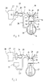
- an example of an internal combustion engine is identified generally by the reference numeral 11.
- the reference numeral 11 For the reasons aforenoted most, if not all, of the components of the engine 11 are shown schematically.
- the engine 11 is comprised of a cylinder block 12 in which one or more cylinder bores 13 are formed. Pistons 14 reciprocate in each cylinder bore 13. The pistons 14 are connected by means of connecting rods 15 to a crankshaft 16. The crankshaft 16 rotates in a crankcase chamber defined by a crankcase member 17 that is affixed to the cylinder block 12 and by the skirt of the cylinder block.
- a cylinder head assembly is affixed to the cylinder block 12 on the side opposite the crankcase chamber 17.
- the cylinder head 18 has a recess which cooperates with the cylinder bore 13 and the head of the piston 14 to form a variable volume chamber 19 which comprises the combustion chamber of the engine.
- the clearance volume at top dead center is defined primarily by the recesses in the cylinder head 18, as is well known in this art.
- the cylinder head 18 is provided with one or more intake passage 21 each of which serves the combustion chamber 19 through a respected intake valve seat 22.
- An induction system indicated generally by the reference numeral 23, serves the intake ports 22 in a manner which will be described.
- a poppet-type intake valve 24 is supported in the cylinder head assembly 18 and cooperates with each intake port 22 for controlling the flow through it.
- the intake valves 24 are operated by any known type of valve actuating mechanism which opens and closes the intake valves 24 in timed sequence with the rotation of the crankshaft 16.
- An overhead camshaft and associated follower system may serve this function.
- Exhaust passages 25 are formed in the cylinder head 18 on the side of the combustion chambers opposite the intake passages 21. These exhaust passages 25 have exhaust ports that are controlled by poppet-type exhaust valves 26 in a known manner. The specific number of exhaust passages 25 and exhaust valves 26 for each cylinder may be varied, as is known in the art.
- One or more spark plugs (not shown) are mounted in the cylinder head 18 and fire the charge which is admitted to the combustion chambers 19 by the induction system 23. This burnt charge is then discharged through the exhaust passages 25.
- the induction system 23 is comprised of an air inlet device 27 which has an atmospheric air inlet 28 into which atmospheric air is inducted.
- the air inlet device 27 may provide a silencing and plenum chamber function.
- an air filter element (not shown) may be positioned in the air inlet device 27 for filtering the inducted air.
- the air that has passed through the air inlet device 27 and its filter, if any, is delivered to an intake passage arrangement, indicated generally by the reference numeral 29 which forms a continuation of the cylinder head intake passage 21.
- These components thus, provide communication between the atmospheric air inlet 28 and the combustion chambers 19.
- a charge former in the form of a carburetor 31 may be positioned in the induction passage 29 downstream of the air inlet device 27.
- the charge former 31 is a sliding piston-type carburetor having a sliding throttle piston 32.
- a valve chamber 33 Downstream of the charge former 31, a valve chamber 33 is provided in which a reed-type check valve 34 is provided.
- the reed-type check valve 34 permits flow through the induction passage when the intake valve 24 is open and the pressure downstream of the reed-type check valve 34 is below the pressure upstream of this valve. However, if the pressure reverses, the reed-type check valve 34 will preclude reverse flow.
- this plenum chamber which communicates with the valve chamber 33 or the intake passage 29 downstream of the check valve 34.
- this plenum chamber is formed by a crankcase chamber 35 in which the crankshaft 16 rotates.
- This crankcase 35 is communicated with the valve chamber 33 downstream of the valve element 34 by means of a communicating passageway 36.
- FIG 2 shows another example of an engine that differs from the engine of Figure 1 only in the way in which the plenum chamber for the intake charging efficiency improvement is formed. For that reason, components of this engine which are the same as the previously described engine have been identified by the same reference numerals and will not be described again, except insofar as is necessary to understand the construction and operation of this exemplified engine.
- a separate plenum chamber, indicated generally by the reference numeral 51 is provided with which the conduit 36 communicates.
- the inertial effect of the air flowing through the reed-type check valve 34 will continue and the air will flow through the conduit 36 into the plenum chamber 51.
- the advantages previously described will be enjoyed. That is, the inertial flow can continue and charging efficiency improved.
- the volume of the plenum chamber 51 is fixed rather than expanding as would the crankcase chamber 35 of the previously described engine.
- the volume of the plenum chamber 51 is, however, made large enough so as to ensure that the continued air flow will occur.
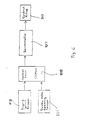
- FIGs 3 through 6 show a preferred embodiment of the invention which has a similar engine construction as the previously described ones. Therefore, components which have been explained when describing the engines shown in Figures 1 and 2 have been identified by the same reference numerals.
- the valve chamber 33 communicates with a branch passageway 101 of a communication system, indicated generally by the reference numeral 102.
- the branch passage way 101 terminates at a control valve 103 which selectively communicates the passageway 101 with either the plenum chamber volume 51 through a first branch passageway 104 or with the crankcase chamber 35 through a second branch passageway 105.
- the valve 103 selectively communicates either the crankcase chamber 35 or the plenum chamber 51 with atmospheric air pressure through a further branch passage way 106.
- the branch passageway 106 communicates either directly through atmospheric air inlet or, more preferably, with the intake device 27. If the intake device 27 includes a filter element, the branch passageway 106 preferably communicates with the air inlet device 27 downstream of the filter element of the air inlet device 27.
- Figure 4 shows the condition of the valve 103 under a certain running condition when the crankcase chamber 35 communicates with the induction system. Under this condition, the plenum chamber 51 is communicated with the air inlet device 27 through the branch passageway 106 so that in can be recharged with fresh air. As will be described later, this position of the control valve 103 may be set under low speed and mid-range performance in some embodiments and under high speed conditions in other embodiments.
- valve 103 When the valve 103 is in this position, the flow continuation during the time when the intake valve 24 is closed will be achieved and also the supercharging effect, afore referred to will be enjoyed. Thus, when the valve 103 is in this position, the engine operates similar to the example-engine of Figure 1.
- crankcase ventilating gases from the crankcase chamber 35 may be discharged into the combustion chambers 19 through the induction system 29. Hence, emission control is also achieved.
- the plenum chamber 51 When the control valve 103 is in the position shown in Figure 5, then the plenum chamber 51 will serve a function which is similar to the example-engine of Figure 2. In this position, however, the crankcase chamber 35 will communicate with the air inlet device 27 downstream of the filter element, if one is provided. Therefore, crankcase ventilation is possible with the crankcase ventilating gases being delivered to the induction system 29 as shown by the arrow in this figure.
- FIG. 6 shows one type of arrangement.
- the control valve 103 is operated by a servomotor, indicated schematically at 107.
- the servomotor 107 is, in turn, controlled by a controller or CPU 108.
- This controller 108 receives certain signals indicative of engine running conditions or operator demand. These signals may comprise an engine speed signal 109 derived from a pulser coil or the like associated with the crankshaft 16.
- a throttle position sensor 111 may be provided that cooperates with the throttle piston 32 to provide a signal indicative of operator demand or load.
- the communication with the crankcase chamber 35 of the induction system 29 through the appropriate positioning of the control valve 103 has the effect of not only improving the flow through the induction system, but also obtaining a supercharging effect.
- one way in which the system may be employed is to maintain the valve 103 in its Figure 4 condition under low and mid-range running conditions and moving the valve to its Figure 5 position under high-speed, high-load conditions. This can be accomplished in response to either of the outputs of the engine speed sensor 109 and/or the throttle position sensor 111.
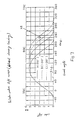
- the standard valve timing for opening and closing of the intake valve in response to crank angle is shown in this figure. It will be seen that the intake valve opens approximately 40° before top dead center and closes at approximately at 210° of crankshaft rotation or about 30° after bottom dead center in engines having conventional induction systems.
- valve 103 This is accomplished by keeping the valve 103 in its Figure 5 position under low and mid-range running and in its Figure 4 position at high speeds and loads, so as to improve charging efficiency. Then the intake valve operating mechanism is set to delay the intake valve closing to a period at 30° to 80° after bottom dead centre, preferably to 70° or 80°. When this is done and under high speed conditions, the supercharging effect will offset the loss in compression ratio, and the expansion ratio can be maintained large. Thus, good power can be achieved without knocking.
- the actual delay in the closing of the intake valve and the operation of the control valve 103 can be utilized to obtain the desired type of engine performance.
- the charge former in the form of the carburetor 31 has been disposed upstream of the reed-type check valve 34.
- the invention may, however, also be practiced in conjunction with arrangements wherein the charge former is positioned downstream of the check valve 34.
- Figure 8 shows such an arrangement, and except for this location, this construction is the same as the embodiments of Figures 3-6. Therefore, like components have been identified by the same reference numerals and will not be described again.
- the charge former or carburetor 31 is disposed between the valve chamber 33 and the engine intake valves 24.
- the communicating passage 101, which serves the control valve 103, is still fed off of the valve chamber 33, and thus is now upstream of the charge former 31, rather than downstream of it in the previously described embodiments.
- Figure 9 shows another embodiment which, as noted, differs from that of Figures 3-6 and Figure 8 only in the relative positions of the charge former 31 and the communicating conduit 101.
- the charge former 32 is again downstream of the check valve 34.
- the communicating passageway 101 is interconnected with the induction passage 29 downstream of the charge former 31.
- he charge former 31 has been a carburetor and specifically a carburetor of the sliding-piston type. It should be readily apparent to those skilled in the art that the invention may be employed in conjunction with other types of carburetors. In addition, the invention may be equally practiced with engines having fuel injection of either the manifold or direct type.
- the fuel may be injected either in the position shown in the embodiments of Figures 3-6 or the position shown in the embodiments of Figures 8 and 9. That is, fuel may be injected either upstream of the check valve 34 or downstream of it.
- the communicating passage 101 may be disposed either upstream or downstream of the point of fuel injection if the fuel injector injects downstream of the check valve 34.
Landscapes
- Engineering & Computer Science (AREA)
- Chemical & Material Sciences (AREA)
- Combustion & Propulsion (AREA)
- Mechanical Engineering (AREA)
- General Engineering & Computer Science (AREA)
- Characterised By The Charging Evacuation (AREA)
- Supercharger (AREA)
- Output Control And Ontrol Of Special Type Engine (AREA)
Claims (14)
- Brennkraftmaschine (11) mit einer Brennkammer (19) und einem Ansaugsystem (23) zum Zuführen einer Ladung zu der Brennkammer (19), wobei das Ansaugsystem (23) eine Einlaßvorrichtung (27) mit einem atmosphärischen Lufteinlaß (28) enthält und einen Ansaugkanal (21), der an einer Ansaugöffnung (22) endet und mit der Brennkammer (19) in Verbindung steht, eine Steuervorrichtung (24) zum aufeinanderfolgenden Öffnen und Schließen der Ansaugöffnung (22) während eines Arbeitszyklusses der Brennkraftmaschine, ein in dem Ansaugkanal (21) stromaufwärts von der Steuervorrichtung (24) angeordnetes Rückschlagventil (34), um einen Fluß durch den Ansaugkanal (21) zur Brennkammer (19) hin zu ermöglichen und einen Rückfluß durch den Ansaugkanal (21) zu unterbinden, Einrichtungen zur Bildung zweier Kammervolumen, die mit dem Ansaugkanal (21) zwischen dem Rückschlagventil (34) und der Steuervorrichtung (24) in Verbindung stehen, wobei ein erstes Kammervolumen durch eine Kurbelkammer (17) gebildet wird, in der eine Kurbelwelle (16) der Brennkraftmaschine (11) umläuft, und ein zweites Kammervolumen (51) unabhängig vom ersten Kammervolumen ausgebildet ist, gekennzeichnet durch ein Steuerventil (103), das zwischen einer ersten Position, in der es den Ansaugkanal (21) stromabwärts vom Rückschlagventil (34) mit dem ersten Kammervolumen (17) verbindet und gleichzeitig den Ansaugkanal (21) stromaufwärts vom Rückschlagventil (34) mit dem weiteren Kammervolumen (51), und einer zweiten Position bewegbar ist, in der es den Ansaugkanal (21) stromabwärts vom Steuerventil (34) mit dem weiteren Kammervolumen (51) verbindet und gleichzeitig den Ansaugkanal (21) stromaufwärts vom Rückschlagventil (34) mit dem ersten Kammervolumen (17) verbindet.
- Brennkraftmaschine nach Anspruch 1, dadurch gekennzeichnet, daß das Steuerventil (103) mit der Einlaßvorrichtung (27) verbunden ist.
- Brennkraftmaschine nach Anspruch 1 oder 2, dadurch gekennzeichnet, daß zusätzliche Luft über den Ansaugkanal (21) durch das Rückschlagventil (34) in die Kurbelkammer (17) gezogen wird, nachdem ein Einlaßventil (24) geschlossen ist zum Erzeugen eines Überladeeffekts auf die Einlaßladung.
- Brennkraftmaschine nach Anspruch 1 oder 2, dadurch gekennzeichnet, daß zusätzliche Luft über den Ansaugkanal (21) durch das Rückschlagventil (34) in das weitere Kammervolumen (51) gezogen wird, nachdem das Einlaßventil (24) geschlossen ist.
- Brennkraftmaschine nach zumindest einem der Ansprüche 1 bis 4, dadurch gekennzeichnet, daß das weitere Kammervolumen (51) durch einen geschlossenen Raum gebildet ist.
- Brennkraftmaschine nach zumindest einem der voranstehenden Ansprüche 1 bis 5, dadurch gekennzeichnet, daß das Kontrollventil (103) in Abhängigkeit von den Motorlaufbedingungen ansteuerbar ist.
- Brennkraftmaschine nach Anspruch 6, dadurch gekennzeichnet, daß das Kontrollventil (103) in seiner ersten Position bei niedrigen und mittleren Motorgeschwindigkeiten und Lasten steht und in seiner zweiten Position bei großen Geschwindigkeiten und Lasten.
- Brennkraftmaschine nach Anspruch 6 oder 7, gekennzeichnet durch eine Verzögerung des Schließens des Einlaßventils (24).
- Brennkraftmaschine nach Anspruch 8, dadurch gekennzeichnet, daß das Einlaßventil (24) frühestens 40° nach dem unteren Totpunkt geschlossen wird.
- Brennkraftmaschine nach Anspruch 9, dadurch gekennzeichnet, daß das Einlaßventil (24) im Bereich von 70 bis 80° nach dem unteren Totpunkt geschlossen ist.
- Brennkraftmaschine nach Anspruch 6, dadurch gekennzeichnet, daß das Steuerventil (103) in seiner ersten Position während hoher Motordrehzahlen und Lasten und in seiner zweiten Position während niedriger und mittlerer Motordrehzahlen und Lasten steht, und daß das Einlaßventil (24) im Bereich von 30 bis 80° nach dem unteren Totpunkt geschlossen ist.
- Brennkraftmaschine nach zumindest einem der voranstehenden Ansprüche 1 bis 11, gekennzeichnet durch einen Ladungsbilder (31), der stromaufwärts vom Rückschlagventil (34) angeordnet ist und ein Treibstoffluftgemisch für den Ansaugkanal (21) zur Verfügung stellt.
- Brennkraftmaschine nach zumindest einem der voranstehenden Ansprüche 1 bis 11, gekennzeichnet durch einen Ladungsbilder (31), der stromabwärts vom Rückschlagventil (34) angeordnet ist und ein Treibstoffluftgemisch für den Ansaugkanal zur Verfügung stellt.
- Brennkraftmaschine nach zumindest einem der voranstehenden Ansprüche 1 bis 11, gekennzeichnet durch eine Treibstoffeinspritzvorrichtung als Ladungsbilder (31) zur Versorgung des Ansaugkanals (21) mit Treibstoff stromabwärts vom Rückschlagventil (34).
Applications Claiming Priority (3)
| Application Number | Priority Date | Filing Date | Title |
|---|---|---|---|
| JP254796/94 | 1994-09-22 | ||
| JP25479694 | 1994-09-22 | ||
| JP25479694A JP3446910B2 (ja) | 1994-09-22 | 1994-09-22 | 4サイクルエンジン |
Publications (3)
| Publication Number | Publication Date |
|---|---|
| EP0703355A2 EP0703355A2 (de) | 1996-03-27 |
| EP0703355A3 EP0703355A3 (de) | 1996-08-14 |
| EP0703355B1 true EP0703355B1 (de) | 1999-06-16 |
Family
ID=17270016
Family Applications (1)
| Application Number | Title | Priority Date | Filing Date |
|---|---|---|---|
| EP95114970A Expired - Lifetime EP0703355B1 (de) | 1994-09-22 | 1995-09-22 | Brennkraftmaschine |
Country Status (3)
| Country | Link |
|---|---|
| US (1) | US5660155A (de) |
| EP (1) | EP0703355B1 (de) |
| JP (1) | JP3446910B2 (de) |
Families Citing this family (29)
| Publication number | Priority date | Publication date | Assignee | Title |
|---|---|---|---|---|
| JPH09324648A (ja) * | 1996-06-06 | 1997-12-16 | Yamaha Motor Co Ltd | クランク室過給式v型エンジン搭載水上走航船 |
| US7281527B1 (en) | 1996-07-17 | 2007-10-16 | Bryant Clyde C | Internal combustion engine and working cycle |
| US7222614B2 (en) | 1996-07-17 | 2007-05-29 | Bryant Clyde C | Internal combustion engine and working cycle |
| US8215292B2 (en) | 1996-07-17 | 2012-07-10 | Bryant Clyde C | Internal combustion engine and working cycle |
| JPH10110619A (ja) * | 1996-10-08 | 1998-04-28 | Yamaha Motor Co Ltd | エンジンの吸気装置 |
| US6055959A (en) * | 1997-10-03 | 2000-05-02 | Yamaha Hatsudoki Kabushiki Kaisha | Engine supercharged in crankcase chamber |
| US6422191B1 (en) * | 1999-08-16 | 2002-07-23 | Delphi Technologies, Inc. | Low evaporative emissions engine management system |
| DE29918516U1 (de) | 1999-10-20 | 2001-03-01 | Dolmar GmbH, 22045 Hamburg | Kompakter Viertakt-Verbrennungsmotor, insbesondere zur Verwendung in einer tragbaren Arbeitsvorrichtung |
| US6302076B1 (en) | 2000-03-13 | 2001-10-16 | Joseph M. Bredy | Internal combustion engine with intake manifold plenum and method of use |
| US20030041818A1 (en) * | 2001-09-05 | 2003-03-06 | Cobb William T. | Internal combustion engine fuel check valve |
| US7201121B2 (en) | 2002-02-04 | 2007-04-10 | Caterpillar Inc | Combustion engine including fluidically-driven engine valve actuator |
| US7178492B2 (en) | 2002-05-14 | 2007-02-20 | Caterpillar Inc | Air and fuel supply system for combustion engine |
| US6688280B2 (en) | 2002-05-14 | 2004-02-10 | Caterpillar Inc | Air and fuel supply system for combustion engine |
| US7252054B2 (en) | 2002-05-14 | 2007-08-07 | Caterpillar Inc | Combustion engine including cam phase-shifting |
| US7191743B2 (en) | 2002-05-14 | 2007-03-20 | Caterpillar Inc | Air and fuel supply system for a combustion engine |
| KR100527441B1 (ko) * | 2002-06-12 | 2005-11-09 | 현대자동차주식회사 | 엔진의 블로 바이 가스 분배장치 |
| JP4357881B2 (ja) | 2003-06-12 | 2009-11-04 | ヤマハ発動機株式会社 | 小型船舶 |
| JP4285648B2 (ja) | 2003-10-03 | 2009-06-24 | 本田技研工業株式会社 | 内燃機関のブローバイガス制御装置 |
| KR20050047218A (ko) * | 2003-11-17 | 2005-05-20 | 현대자동차주식회사 | 내연기관 엔진의 포지티브 크랭크케이스 벤틸레이션 시스템 |
| JP2006002633A (ja) | 2004-06-16 | 2006-01-05 | Yamaha Marine Co Ltd | 水ジェット推進艇 |
| JP2006037730A (ja) | 2004-07-22 | 2006-02-09 | Yamaha Marine Co Ltd | 過給式エンジンの吸気装置 |
| JP2006083713A (ja) | 2004-09-14 | 2006-03-30 | Yamaha Marine Co Ltd | 過給装置の潤滑構造 |
| PT1640601E (pt) * | 2004-09-28 | 2007-02-28 | Magneti Marelli Powertrain Spa | Colector de admissão com recipiente de ar para um motor de combustão interna |
| JP2007062432A (ja) | 2005-08-29 | 2007-03-15 | Yamaha Marine Co Ltd | 小型滑走艇 |
| US7464694B2 (en) * | 2006-06-23 | 2008-12-16 | Chun-Hsiung Chang | Variable flow control method and device between air intake and throttle |
| CN101100960B (zh) * | 2006-07-04 | 2011-08-17 | 张俊雄 | 进气口至节气门之间可变控流的方法及装置 |
| US7802552B1 (en) * | 2007-04-27 | 2010-09-28 | TSR Technologies, L.L.C. | Gas channeling cylinder head assembly |
| JP5244691B2 (ja) * | 2009-05-11 | 2013-07-24 | ヤマハ発動機株式会社 | 火花点火式内燃機関 |
| CN115217660B (zh) * | 2022-07-12 | 2023-07-21 | 广州汽车集团股份有限公司 | 充气效率的修正方法及装置、设备、计算机可读存储介质 |
Family Cites Families (17)
| Publication number | Priority date | Publication date | Assignee | Title |
|---|---|---|---|---|
| US3810454A (en) * | 1972-09-25 | 1974-05-14 | J Hunt | Pollution free fuel inlet system for internal combustion engines |
| US5253614A (en) * | 1979-06-27 | 1993-10-19 | Yamaha Hatsudoki Kabushiki Kaisha | Intake system for engine |
| JPS56162222A (en) * | 1980-05-17 | 1981-12-14 | Honda Motor Co Ltd | Internal-combustion engine |
| JPS5713221A (en) * | 1980-06-28 | 1982-01-23 | Yamaha Motor Co Ltd | Intake apparatus of engine |
| JPS57188722A (en) * | 1981-05-15 | 1982-11-19 | Honda Motor Co Ltd | Secondary air introducing device in engine |
| JPS57188757A (en) * | 1981-05-15 | 1982-11-19 | Yamaha Motor Co Ltd | Air inlet device for four-cycle engine |
| JPS58160514A (ja) * | 1982-03-19 | 1983-09-24 | Honda Motor Co Ltd | 内燃機関の吸入装置 |
| JPS61200326A (ja) * | 1985-02-28 | 1986-09-04 | Honda Motor Co Ltd | 過給式4サイクルエンジン |
| GB8525835D0 (en) * | 1985-10-19 | 1985-11-20 | Rolls Royce Motors Ltd | Reciprocating i c engines |
| JPS6394027A (ja) * | 1986-10-08 | 1988-04-25 | Mazda Motor Corp | 過給機付エンジンの吸気装置 |
| CA1328588C (en) * | 1987-05-15 | 1994-04-19 | Honda Giken Kogyo Kabushiki Kaisha (Also Trading As Honda Motor Co., Ltd .) | Internal combustion engine |
| US4986225A (en) * | 1990-06-08 | 1991-01-22 | General Motors Corporation | Intake reservoir system for an engine having a check valve |
| US4991547A (en) * | 1990-06-08 | 1991-02-12 | General Motors Corporation | Intake port pressure control system for engine induction system |
| US5009199A (en) * | 1990-06-08 | 1991-04-23 | General Motors Corporation | Intake reservoir for an engine having a check valve |
| JP3025332B2 (ja) * | 1991-03-28 | 2000-03-27 | マツダ株式会社 | エンジンの排気ガス還流装置 |
| US5129367A (en) * | 1991-04-08 | 1992-07-14 | General Motors Corporation | Intermittent bypass system for a check valve |
| US5501203A (en) * | 1995-01-06 | 1996-03-26 | Briggs & Stratton Corporation | Dynamic gas seal for internal combustion engines |
-
1994
- 1994-09-22 JP JP25479694A patent/JP3446910B2/ja not_active Expired - Fee Related
-
1995
- 1995-09-21 US US08/531,732 patent/US5660155A/en not_active Expired - Fee Related
- 1995-09-22 EP EP95114970A patent/EP0703355B1/de not_active Expired - Lifetime
Also Published As
| Publication number | Publication date |
|---|---|
| JPH0893484A (ja) | 1996-04-09 |
| JP3446910B2 (ja) | 2003-09-16 |
| EP0703355A2 (de) | 1996-03-27 |
| US5660155A (en) | 1997-08-26 |
| EP0703355A3 (de) | 1996-08-14 |
Similar Documents
| Publication | Publication Date | Title |
|---|---|---|
| EP0703355B1 (de) | Brennkraftmaschine | |
| US5000131A (en) | Exhaust port control valve for two stroke engine | |
| US6148794A (en) | Induction control system for multi-valve engine | |
| US5063888A (en) | Exhaust control valve system for parallel multi-cylinder two-cycle engine | |
| US4617896A (en) | Internal combustion engine having three intake valves per cylinder | |
| US5950582A (en) | Internal combustion engine with variable camshaft timing and intake valve masking | |
| US5063887A (en) | Exhaust control valve system for parallel multi-cylinder two-cycle engine | |
| US5913298A (en) | Valve timing system for engine | |
| US5553590A (en) | Intake control valve | |
| US4998512A (en) | Exhaust port control system for two stroke engine | |
| US5477823A (en) | Control valve for engine intake control system | |
| US4867109A (en) | Intake passage arrangement for internal combustion engines | |
| US6131554A (en) | Engine having combustion control system | |
| US5255649A (en) | Intake air control system for the engine | |
| US4860709A (en) | Engine induction system and method | |
| US4627400A (en) | Porting system for internal combustion engine | |
| US4660530A (en) | Intake system for internal combustion engine | |
| US5832881A (en) | Supplementary port for two stroke engine | |
| EP0520518B1 (de) | Einlasssystem für eine Brennkraftmaschine | |
| US4714059A (en) | Single overhead camshaft engine | |
| JPH08218879A (ja) | 4サイクルエンジンの吸気構造 | |
| US5720259A (en) | Fuel injected multi-valve engine | |
| US6367448B1 (en) | Engine control | |
| EP0278032B1 (de) | Hochleistungsauspuffanlage für Brennkraftmaschine | |
| JP2634466B2 (ja) | 4サイクル内燃機関 |
Legal Events
| Date | Code | Title | Description |
|---|---|---|---|
| PUAI | Public reference made under article 153(3) epc to a published international application that has entered the european phase |
Free format text: ORIGINAL CODE: 0009012 |
|
| AK | Designated contracting states |
Kind code of ref document: A2 Designated state(s): FR GB IT |
|
| PUAL | Search report despatched |
Free format text: ORIGINAL CODE: 0009013 |
|
| AK | Designated contracting states |
Kind code of ref document: A3 Designated state(s): FR GB IT |
|
| 17P | Request for examination filed |
Effective date: 19970130 |
|
| 17Q | First examination report despatched |
Effective date: 19970228 |
|
| GRAG | Despatch of communication of intention to grant |
Free format text: ORIGINAL CODE: EPIDOS AGRA |
|
| GRAG | Despatch of communication of intention to grant |
Free format text: ORIGINAL CODE: EPIDOS AGRA |
|
| GRAH | Despatch of communication of intention to grant a patent |
Free format text: ORIGINAL CODE: EPIDOS IGRA |
|
| GRAH | Despatch of communication of intention to grant a patent |
Free format text: ORIGINAL CODE: EPIDOS IGRA |
|
| GRAA | (expected) grant |
Free format text: ORIGINAL CODE: 0009210 |
|
| AK | Designated contracting states |
Kind code of ref document: B1 Designated state(s): FR GB IT |
|
| PG25 | Lapsed in a contracting state [announced via postgrant information from national office to epo] |
Ref country code: IT Free format text: LAPSE BECAUSE OF FAILURE TO SUBMIT A TRANSLATION OF THE DESCRIPTION OR TO PAY THE FEE WITHIN THE PRE;WARNING: LAPSES OF ITALIAN PATENTS WITH EFFECTIVE DATE BEFORE 2007 MAY HAVE OCCURRED AT ANY TIME BEFORE 2007. THE CORRECT EFFECTIVE DATE MAY BE DIFFERENT FROM THE ONE RECORDED.SCRIBED TIME-LIMIT Effective date: 19990616 |
|
| ET | Fr: translation filed | ||
| PLBE | No opposition filed within time limit |
Free format text: ORIGINAL CODE: 0009261 |
|
| STAA | Information on the status of an ep patent application or granted ep patent |
Free format text: STATUS: NO OPPOSITION FILED WITHIN TIME LIMIT |
|
| 26N | No opposition filed | ||
| REG | Reference to a national code |
Ref country code: GB Ref legal event code: IF02 |
|
| PGFP | Annual fee paid to national office [announced via postgrant information from national office to epo] |
Ref country code: FR Payment date: 20020910 Year of fee payment: 8 |
|
| PGFP | Annual fee paid to national office [announced via postgrant information from national office to epo] |
Ref country code: GB Payment date: 20020918 Year of fee payment: 8 |
|
| PG25 | Lapsed in a contracting state [announced via postgrant information from national office to epo] |
Ref country code: GB Free format text: LAPSE BECAUSE OF NON-PAYMENT OF DUE FEES Effective date: 20030922 |
|
| GBPC | Gb: european patent ceased through non-payment of renewal fee |
Effective date: 20030922 |
|
| PG25 | Lapsed in a contracting state [announced via postgrant information from national office to epo] |
Ref country code: FR Free format text: LAPSE BECAUSE OF NON-PAYMENT OF DUE FEES Effective date: 20040528 |
|
| REG | Reference to a national code |
Ref country code: FR Ref legal event code: ST |