EP0703357B1 - Brennkraftmaschine mit Steuerung der Zahl der aktiven Zylinder - Google Patents
Brennkraftmaschine mit Steuerung der Zahl der aktiven Zylinder Download PDFInfo
- Publication number
- EP0703357B1 EP0703357B1 EP95109646A EP95109646A EP0703357B1 EP 0703357 B1 EP0703357 B1 EP 0703357B1 EP 95109646 A EP95109646 A EP 95109646A EP 95109646 A EP95109646 A EP 95109646A EP 0703357 B1 EP0703357 B1 EP 0703357B1
- Authority
- EP
- European Patent Office
- Prior art keywords
- valve
- engine
- stoppage
- cylinder
- cylinders
- Prior art date
- Legal status (The legal status is an assumption and is not a legal conclusion. Google has not performed a legal analysis and makes no representation as to the accuracy of the status listed.)
- Expired - Lifetime
Links
- 238000002485 combustion reaction Methods 0.000 title claims description 57
- 239000012530 fluid Substances 0.000 claims description 39
- 239000000446 fuel Substances 0.000 claims description 24
- 238000002347 injection Methods 0.000 description 10
- 239000007924 injection Substances 0.000 description 10
- 230000009467 reduction Effects 0.000 description 10
- 238000010276 construction Methods 0.000 description 9
- 238000005086 pumping Methods 0.000 description 8
- 238000007599 discharging Methods 0.000 description 7
- 238000004880 explosion Methods 0.000 description 7
- 238000010586 diagram Methods 0.000 description 5
- 230000003247 decreasing effect Effects 0.000 description 4
- 239000007789 gas Substances 0.000 description 3
- 239000000567 combustion gas Substances 0.000 description 2
- 230000006835 compression Effects 0.000 description 2
- 238000007906 compression Methods 0.000 description 2
- 230000006866 deterioration Effects 0.000 description 2
- 239000000203 mixture Substances 0.000 description 2
- 238000010008 shearing Methods 0.000 description 2
- 230000004323 axial length Effects 0.000 description 1
- 239000000498 cooling water Substances 0.000 description 1
- 230000000694 effects Effects 0.000 description 1
- 230000001788 irregular Effects 0.000 description 1
- 230000002045 lasting effect Effects 0.000 description 1
- 230000002093 peripheral effect Effects 0.000 description 1
- 230000000630 rising effect Effects 0.000 description 1
- 230000001360 synchronised effect Effects 0.000 description 1
Images








Classifications
-
- F—MECHANICAL ENGINEERING; LIGHTING; HEATING; WEAPONS; BLASTING
- F01—MACHINES OR ENGINES IN GENERAL; ENGINE PLANTS IN GENERAL; STEAM ENGINES
- F01L—CYCLICALLY OPERATING VALVES FOR MACHINES OR ENGINES
- F01L13/00—Modifications of valve-gear to facilitate reversing, braking, starting, changing compression ratio, or other specific operations
- F01L13/0015—Modifications of valve-gear to facilitate reversing, braking, starting, changing compression ratio, or other specific operations for optimising engine performances by modifying valve lift according to various working parameters, e.g. rotational speed, load, torque
- F01L13/0036—Modifications of valve-gear to facilitate reversing, braking, starting, changing compression ratio, or other specific operations for optimising engine performances by modifying valve lift according to various working parameters, e.g. rotational speed, load, torque the valves being driven by two or more cams with different shape, size or timing or a single cam profiled in axial and radial direction
-
- F—MECHANICAL ENGINEERING; LIGHTING; HEATING; WEAPONS; BLASTING
- F01—MACHINES OR ENGINES IN GENERAL; ENGINE PLANTS IN GENERAL; STEAM ENGINES
- F01L—CYCLICALLY OPERATING VALVES FOR MACHINES OR ENGINES
- F01L1/00—Valve-gear or valve arrangements, e.g. lift-valve gear
- F01L1/26—Valve-gear or valve arrangements, e.g. lift-valve gear characterised by the provision of two or more valves operated simultaneously by same transmitting-gear; peculiar to machines or engines with more than two lift-valves per cylinder
- F01L1/267—Valve-gear or valve arrangements, e.g. lift-valve gear characterised by the provision of two or more valves operated simultaneously by same transmitting-gear; peculiar to machines or engines with more than two lift-valves per cylinder with means for varying the timing or the lift of the valves
-
- F—MECHANICAL ENGINEERING; LIGHTING; HEATING; WEAPONS; BLASTING
- F02—COMBUSTION ENGINES; HOT-GAS OR COMBUSTION-PRODUCT ENGINE PLANTS
- F02D—CONTROLLING COMBUSTION ENGINES
- F02D13/00—Controlling the engine output power by varying inlet or exhaust valve operating characteristics, e.g. timing
- F02D13/02—Controlling the engine output power by varying inlet or exhaust valve operating characteristics, e.g. timing during engine operation
- F02D13/06—Cutting-out cylinders
-
- F—MECHANICAL ENGINEERING; LIGHTING; HEATING; WEAPONS; BLASTING
- F02—COMBUSTION ENGINES; HOT-GAS OR COMBUSTION-PRODUCT ENGINE PLANTS
- F02B—INTERNAL-COMBUSTION PISTON ENGINES; COMBUSTION ENGINES IN GENERAL
- F02B75/00—Other engines
- F02B75/02—Engines characterised by their cycles, e.g. six-stroke
- F02B2075/022—Engines characterised by their cycles, e.g. six-stroke having less than six strokes per cycle
- F02B2075/027—Engines characterised by their cycles, e.g. six-stroke having less than six strokes per cycle four
-
- Y—GENERAL TAGGING OF NEW TECHNOLOGICAL DEVELOPMENTS; GENERAL TAGGING OF CROSS-SECTIONAL TECHNOLOGIES SPANNING OVER SEVERAL SECTIONS OF THE IPC; TECHNICAL SUBJECTS COVERED BY FORMER USPC CROSS-REFERENCE ART COLLECTIONS [XRACs] AND DIGESTS
- Y02—TECHNOLOGIES OR APPLICATIONS FOR MITIGATION OR ADAPTATION AGAINST CLIMATE CHANGE
- Y02T—CLIMATE CHANGE MITIGATION TECHNOLOGIES RELATED TO TRANSPORTATION
- Y02T10/00—Road transport of goods or passengers
- Y02T10/10—Internal combustion engine [ICE] based vehicles
- Y02T10/12—Improving ICE efficiencies
Definitions
- the present invention relates to a cylinder number-controlled internal combustion engine in which the operation of one or more of cylinders can be stopped.
- Such internal combustion engines are conventionally known, for example, from Japanese Patent Application Laid-open No. 78709/90 (JP-A-2078709).
- the above known internal combustion engine is of a construction such that only one or more predetermined particular cylinder(s) can be stopped. If the cylinder-stopped operation has been continued for a long time, the temperature of a peripheral portion within the stopped cylinder (e.g., the temperature of a cylinder wall surface, a top of a cylinder, a wall surface of a combustion chamber, there is a possibility that an engine valve or the like) is dropped as compared with that during a burned operation, and/or an unbalance of an oil rise and drop phenomenon in the stopped cylinder, a sticking of the engine valve, a compression leakage and the like may be produced.
- a peripheral portion within the stopped cylinder e.g., the temperature of a cylinder wall surface, a top of a cylinder, a wall surface of a combustion chamber, there is a possibility that an engine valve or the like
- a control is also conducted such that the stopped cylinder is restored to an operative state after a lapse of a predetermined time from the start of the stoppage of the cylinder.
- the generic US-A-4991558 discloses a cylinder number-controlled two stroke engine comprising fuel injectors disposed for each of a plurality of cylinders to govern execution and stoppage of fuel combustion.
- the operation of one or more of said cylinders is stopped by stopping an operation of the fuel injectors.
- the engine further includes a control unit for controlling a switchover between the operation and stoppage of said fuel injectors, such that the operation and stoppage of all cylinders are repeated according to a previously established cylinder stoppage cycle when said engine is in a cylinder-operation-stopped operation state.
- the control mode of the control unit switches between an idle operation with one predetermined injection skip mode and a normal operation mode. Every cylinder changes rapidly between injection cycles and non-injection cycles lasting at most two crank rotations.
- the EP-A-0367448 discloses a cylinder number-controlled engine comprising engine valves disposed in a plurality of cylinders, respectively, such that an operation of one or more of the plurality of cylinders is stopped by stopping an operation of the engine valve disposed in such a cylinder.
- the engine further includes valve operation and stoppage switchover means provided for said respective cylinders and capable of switching over the operation and stoppage of said engine valves independently from each other.
- a control unit controls an operation of said valve operation and stoppage switchover means, such that the operation and stoppage of said engine valves in all said cylinders are repeated according to a previously established engine valve stoppage cycle when said engine is in a cylinder operation-stopped operational state.
- a variable cylinder-number controlled internal combustion engine comprising combustion governing means disposed for each of a plurality of cylinders to govern execution and stoppage of fuel combustion, such that an operation of each of said cylinders is stopped by a stopping operation of the combustion governing means
- said internal combustion engine further includes a control unit for controlling a switchover between a normal operation and stopping operation of said combustion governing means for each of the cylinders such that the operation and stoppage of each said cylinder is repeated according to a previously established cylinder operation and stoppage order different from a cylinder operation and stoppage order of at least one other said cylinder when said engine is in a cylinder-operation-stopped operational state
- said control unit being capable of selecting any of a plurality of control modes each having a different cylinder operation and stoppage order in accordance with the operational state of said engine, and one of said control modes includes a frequency of said stoppage operation of each said cylinder for every set number of rotations of an engine crankshaft that
- the cylinders can be stopped, thus preventing one or more of the cylinders from being brought into an incompletely warmed state when the engine is restored to the all cylinder-operated state after continuation of the cylinder-stopped operation over a long time, and moreover to select the cylinder stoppage suitable to the operational state of the engine.
- the number-controlled internal combustion engine comprises engine valves disposed in a plurality of cylinders, respectively, such that an operation of one or more of the plurality of cylinders is stopped by stopping an operation of the engine valve disposed in such cylinder, wherein the internal combustion engine further includes valve operation and stoppage switchover means provided for the respective cylinders and capable of switching over the operation and stoppage of the engine valves independently from each other, and a control unit for controlling an operation of the valve operation and stoppage switchover means, such that the operation and stoppage of the engine valves in all the cylinders are repeated according to a previously established engine valve stoppage cycle, when the engine is in a cylinder operation-stopped operational state.
- the engine valves in the cylinders can be closed and stopped, thus preventing one or more of the cylinders from being brought into an incompletely warmed state when te engine is restored to the all cylinder-operated state after continuation of the cylinder-stopped operation over a long time, and provding a reduction in pumping loss and a reduction in fuel consumption by stoppage of the cylinder as a result of stoppage of the operation of the engine valve.
- control unit is capable of selecting any of the control modes in accordance with the operational state of the engine.
- the engine valve stoppage cycle is established so as to include a stoppage cycle in which a frequency of stoppage of the engine valve for every set number of rotations of a crankshaft is differentiated between the plurality of cylinders.
- a plurality of control modes are established such that engine valve stoppage cycles for the cylinders are different from one another, and frequencies of stoppage of the engine valves in the cylinders for every set number of rotations of a crankshaft are made uniform between the cylinders, and the control unit is capable of selecting any of the control modes in accordance with the operational state of the engine.
- the engine valve stoppage cycle is set for each of the cylinders and is established such that phases of the engine valve stoppage cycles for at least two of the cylinders are different from each other.
- valve operation and stoppage switchover means for each of the cylinders is arranged such that the operation and stoppage of the engine valve is switched by a fluid pressure, and that the engine further includes solenoid fluid pressure control valve means which are independently connected to the valve operation and stoppage switchover means for the cylinders, respectively, and controlled by the control unit.
- the valve operation and stoppage switchover means for each of the cylinders is arranged such that the operation and stoppage of the engine valve is switched by a fluid pressure
- the engine further includes a solenoid fluid pressure control valve means disposed for each of groups of the cylinders and controlled by the control means, and a mechanically-operated valve which is provided between each of the solenoid fluid pressure control valve means and each of the valve operation and stoppage switchover means for determining a timing of supply of working fluid to each of the valve operation and stoppage switchover means by mechanical operation related to the rotating operation of the crankshaft.
- a multi-cylinder internal combustion engine is, for example, a four-cylinder internal combustion engine including first, second, third and fourth cylinders C 1 , C 2 , C 3 and C 4 mounted in parallel in an engine body E.
- Each of the cylinders C 1 , C 2 , C 3 and C 4 has an intake valve V I disposed therein as an engine valve for controlling the timing of supply of an air-fuel mixture from an intake manifold M I into each of the cylinders C 1 , C 2 , C 3 and C 4 , and an exhaust valve V E disposed therein as an engine valve for controlling the timing of discharge of an exhaust gas from each of the cylinders C 1 , C 2 , C 3 and C 4 into an exhaust manifold M E .
- a fuel injection valve V FI corresponding to each of the cylinders C 1 , C 2 , C 3 and C 4 is disposed in the intake manifold M I , and a spark plug P is disposed in each of the cylinders C 1 , C 2 , C 3 and C 4 and ignited by an igniter 81.
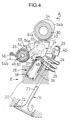
- the intake valve V I in the first cylinder C 1 includes an umbrella-like valve member 22 integrally provided on a valve stem and capable of opening and closing an intake valve bore 21 provided in a cylinder head 20 in the engine body E.
- the intake valve V I is carried in the cylinder head 20 for movement in opening and closing directions, i.e., in a longitudinal direction of the valve stem 23.
- a valve spring 25 is compressed between a retainer 24 mounted at an upper end of the valve stem 23 and the cylinder head 20, and the intake valve V I is biased in a direction to close the intake valve bore 21 by the valve member 22, i.e., in the valve closing direction.
- a rocker arm shaft 26 is fixed and positioned above the cylinder head 20 to extend in a direction of arrangement of the cylinders C 1 to C 4 .
- a base end of a driving rocker arm 27 and a base end of a free rocker end adjacent the driving rocker arm 27 are swingably carried adjacent to each other on the rocker arm shaft 26.
- a tappet screw 29 is threadedly inserted through n a tip end of the driving rocker arm 27 to abut against an upper end of the valve stem 23 of the intake valve V I , so that the advanced and retreated positions can be adjusted.
- a cam shaft 30 operatively connected to a crankshaft (not shown) at a reduction ratio of 1/2 is rotatably disposed above the rocker arms 27 and 28 and has an axis parallel to the rocker arm shaft 26.
- the cam shaft 30 includes a stopping portion 32 which is integrally provided thereon to come into sliding contact with a slipper 31 mounted on an upper surface of the driving rocker arm 27, and an operating cam 34 which is also integrally provided thereon to come into sliding contact with a cam slipper 33 mounted on an upper surface of the free rocker arm 28.
- the stopping portion 32 is raised from an outer surface of the cam shaft 30 into a circular shape spaced apart at an equal distance from an axis of the cam shaft 30.
- the operating cam 34 includes a base-circle portion 34a spaced apart at a distance from the axis of the cam shaft 30, which is equal to the outside radius of the stopping portion 32, and a cam lobe 34b projecting radially outwardly from the base-circle portion 34a.
- the driving rocker arm 27 is biased toward the stopping portion 32 by the valve spring 25, while the free rocker arm 28 is biased toward the operating cam 34 by a lost motion mechanism 35 provided between the free rocker arm 28 itself and the cylinder head 20.
- the lost motion mechanism 35 includes a bottomed guide sleeve 36 fixedly mounted in the cylinder head 20, a bottomed cylindrical lifter 37 slidably received in the guide sleeve 36, and a spring 38 compressed between the guide sleeve 36 and the lifter 37.
- the free rocker arm 28 is biased normally into sliding contact with the operating cam 34 by abutment of the lifter 37 biased upwardly by the spring 38 against a lower surface of the free rocker arm 28.
- a valve operation and stoppage switchover means 40 1 is provided between the driving rocker arm 27 and the free rocker arm 28 and is capable of connecting and disconnecting the rocker arms 27 and 28 to and from each other, i.e., switchable by a hydraulic pressure as a fluid pressure between a state in which it connects the rocker arms 27 and 28 to each other to open and close the intake valve V I by the operating cam 34, and a state in which it disconnects the rocker arms 27 and 28 from each other to stop the intake valve V I by the stopping portion 32.
- the valve operation and stoppage switchover means 40 1 includes a first piston 42 slidably received in the free rocker arm 28 and having one end facing a hydraulic pressure chamber 41, a second piston 43 slidably received in the free rocker arm 28 and having one end opposed to the other end of the first piston 42, a spring 44 compressed between the first and second pistons 42 and 43, a switchover pin 45 having one end abutting against the other end of the second piston 43, a limiting member 46 slidably received in the driving rocker arm 27 and having one end abutting against the other end of the switchover pin 45, and a return spring 47 compressed between the limiting member 46 and the driving rocker arm 27.
- the return spring 47 has a preset load which is set larger than the preset load of the spring 44.
- the first piston 42 is formed into a bottomed cylindrical shape with one end closed, and the hydraulic pressure chamber 41 is defined between the one end of the first piston 42 and the free rocker arm 28.
- a communication passage 48 is provided in the free rocker arm 28 to lead to the hydraulic pressure chamber 41 and is normally in communication with an oil passage 49 which is coaxially provided within the rocker arm shaft 26.
- the second piston 43 is formed into a relatively short columnar shape.
- the switchover pin 45 is slidable between a position in which it is fitted astride a boundary between the free rocker arm 28 and the driving rocker arm 27, as shown in Fig.5, and a position in which it is fitted in the driving rocker arm 27, so that its surface abutting against the second piston 43 is located at a position corresponding to the boundary between the driving rocker arm 27 and the free rocker arm 28.
- the switchover pin 45 is formed into a short columnar shape.
- the limiting member 46 is formed into a bottomed cylindrical shape with one end abutting against the switchover pin 45 being closed, and has a collar portion 46a which is provided at the other end thereof to protrude radially outwardly and which is slidably received in the driving rocker arm 27.
- a retaining ring 50 is fitted in the driving rocker arm 27 and abuts against the collar portion 46a of the limiting member 46 to limit the movement of the limiting member 46 toward the one end of the limiting member, i.e., toward the switchover pin 45.
- the axial lengths of the switchover pin 45 and the limiting member 46 are set so that when the limiting member 46 has been moved to a position in which its movement is limited by the retaining ring 50, as shown in Fig.5, the switchover pin 45 abutting against the limiting member 46 is located astride the boundary between the driving rocker arm 27 and the free rocker arm 28 to connect the rocker arms 27 and 28 to each other, and when the limiting member 46 has been moved, while compressing the return spring 47, to a position to abut against the driving rocker arm 27, as shown in Fig.6, the surface of the switchover pin 45 abutting against the second piston 43 is located at the position corresponding to the boundary between the rocker arms 27 and 28.
- annular engage recess 51 is provided in an outer surface of the first piston 42 at its end adjacent the second piston 43, and an annular engage groove 52 is provided in an outer periphery of the first piston 42.
- a trigger mechanism 53 is associated with such valve operation and stoppage switchover means 40 1 for limiting the timing of operation of the valve operation and stoppage switchover means 40 1 .
- the trigger mechanism 53 includes a trigger plate 54 which is swingable relative to the rocker arms 27 and 28 about an axis of the rocker arm shaft 26 between a position in which it is in engagement with the engage recess 51 or the engage groove 52 in the first piston 42 to limit the movement of the first piston 42, and a position in which it is out of engagement with the engage recess 51 or the engage groove 52 in the first piston 42 to permit the movement of the first piston 42.
- a slit 55 is provided in the free rocker arm 28, so that its position corresponds to the engage recess 51 in a condition in which the first piston 42 has been moved to the maximum toward the hydraulic pressure chamber 41, as shown in Fig.5.
- the engage groove 52 is provided in the outer periphery of the first piston 42, so that it is located at a position corresponding to the slit in a condition in which the first and second pistons 42 and 43 abutting against each other as shown in Fig.6 have been moved to the maximum to a position in which the volume of the hydraulic pressure chamber 41 is maximized.
- the trigger plate 54 is rotatably carried on the rocker arm shaft 26.
- the trigger plate 54 has an engage plate portion 54a integrally provided thereon and capable of being disengageably engaged into the engage recess 51 or the engage groove 52 from the slit 55.
- a stopper pin 56 is fixedly mounted in the engine body E to extend toward the free rocker arm 28, and a stopper 54b is provided to protrude from the trigger plate 54 and capable of abutting against the stopper pin 56 from below.
- a torsion spring 57 is locked at its one end to the stopper pin 56 to surround the rocker arm shaft 26 and at the other end thereof to the trigger plate 54 from above.
- the trigger plate 54 is biased in a direction to cause the stopper 54b to abut against the stopper pin 56 by the torsion spring 57.
- the position of the stopper pin 56 is established so that when the free rocker arm 28 is in a stationary state to abut against the base-circle portion 34a of the operating cam 34 in a condition in which the stopper is in abutment against the stopper pin 56, the engage plate portion 54a of the trigger plate 54 is capable of being engaged into the engage recess 51 or the engage groove 52 from the slit 55, and when the free rocker arm 28 is swung in the valve opening direction by the cam lobe 34b of the operating cam 34, the engage plate portion 54a is disengaged from the slit 55.
- the first piston 42 is moved by the spring force of the spring 44 to a position to minimize the volume of the hydraulic pressure chamber 41 in response to the free rocker arm 28 being pushed down to disengage the engage plate portion 54a from the engage groove 52. Then, when the free rocker arm 28 starts to come into sliding contact with the base-circle portion 34a of the operating cam 34, thereby causing the axes of the switchover pin 45 and the second piston 43 to be aligned with each other, the switchover pin 45 is moved to a position astride the boundary between the rocker arms 27 and 28 by the spring force of the return spring 47 to connect the rocker arms 27 and 28 to each other.
- the exhaust valve V E in the first cylinder C 1 is connected to a valve operating device having a construction similar to that of the above-described intake valve V I and commonly including the cam shaft 30. During operation of the intake valve V I , the exhaust valve V E is also opened and closed. When the intake valve V I is stopped, the exhaust valve is also stopped.
- valve operating devices each having a construction similar to that in the first cylinder C 1 .
- Valve operation and stoppage switchover means 40 2 , 40 3 and 40 4 each having a construction similar to that of the valve operation and stoppage switchover means 40 1 for the first cylinder C 1 are also independently provided in the valve operating devices for the second, third and fourth cylinders C 2 , C 3 and C 4 .
- oil passages 49 leading to the hydraulic pressure chambers 41 in the valve operation and stoppage switchover means 40 1 , 40 2 , 40 3 and 40 4 are provided in the rocker arm shafts 26 independently for every cylinders C 1 , C 2 , C 3 and C 4 .
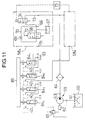
- valve operation and stoppage switchover means 40 1 , 40 2 , 40 3 and 40 4 for the cylinders C 1 , C 2 , C 3 and C 4 are connected to a common hydraulic pressure source 59 through separate solenoid fluid pressure control valve means 58 1 , 58 2 , 58 3 and 58 4 , respectively.
- the hydraulic pressure source 59 includes a reservoir 60 for storing a working oil therein, a pump 63 driven by a crankshaft 62 of the engine and having a drawing port connected to the reservoir 60 through a filter 61, a filter 64 connected to a discharge port of the pump 63, and a relief valve 65 interposed between the discharge port and the reservoir 60.
- a substantially constant hydraulic pressure is delivered from the hydraulic pressure source 59 via filter 64.
- the solenoid fluid pressure control valve 58 1 includes a switchover control valve 72 interposed between a supplying oil passage 66 leading to the hydraulic pressure source 59 as well as a releasing oil passage 68 leading to a reservoir 67 and an oil passage 70 connected to the supplying oil passage 66 and having a constriction 69 incorporated therein as well as an oil passage 71 connected to the oil passage 49 in the valve operation and stoppage switchover means 40 1 , and a solenoid switchover valve 74 incorporated in a pilot passage 73 connected to the supplying oil passage 66.
- the reservoir 67 may be identical with the reservoir 60 of the hydraulic pressure source 59.
- the switchover control valve 72 is operated for switchover in response to a pilot hydraulic pressure from the pilot oil passage 73 and switchable between a state in which it permits the oil passages 70 and 71 to communicate with the releasing oil passage 68 in a condition in which the pilot hydraulic pressure from the pilot oil passage 73 is not applied, i.e., a state in which it releases the hydraulic pressure in the hydraulic pressure chamber 41 in the valve operation/stoppage switchover means 40 1 to open and close the intake valve V I and the exhaust valve V E , and a state in which it permits the oil passage 71 to communicate with the supplying oil passage 66 and cuts off the communication of the oil passage 70 with the releasing oil passage 68 in a condition in which the pilot hydraulic pressure from the pilot oil passage 73 has been applied, i.e., in a state in which it permits the hydraulic pressure to be applied to the hydraulic pressure chamber 41 in the valve operation/stoppage switchover means 40 1 to close and stop the intake valve V I and the exhaust valve V E .
- the solenoid switchover valve 74 is switchable between a state in which it cuts off the communication of the pilot passage 73 and permits a downstream portion of the pilot oil passage 73 from the solenoid switchover valve 74 to communicate with the reservoir 67 by deenergization thereof, and a state in which it permits the communication of the pilot oil passage 73 by energization thereof.
- the switchover control valve 72 when the solenoid switchover valve 74 is in the deenergized state, the switchover control valve 72 is in a state in which it releases the hydraulic pressure in the hydraulic pressure chamber 41 in the valve operation/stoppage switchover means 40 1 to open and close the intake valve V I and the exhaust valve V E , and when the solenoid switchover valve 74 is in the energized state, the switchover control valve 72 is in a state in which it applies the hydraulic pressure to the hydraulic pressure chamber 41 in the valve operation/stoppage switchover means 40 1 to stop the intake valve V I and the exhaust valve V E .
- the solenoid fluid pressure control valve means 68 2 , 68 3 and 68 4 independently corresponding to the valve operation/stoppage switchover means 40 2 , 40 3 and 40 4 for the second, third and fourth cylinders C 2 , C 3 and C 4 are constructed in the same manner as is the above-described solenoid fluid pressure control valve means 68 1 .
- the control unit 75 includes an operational state detecting means 76 for detecting he operational state of the engine based on an accelerator opening degree ⁇ ACC , a number N E of revolutions of the engine, an intake pressure P B , a throttle opening degree ⁇ TH , a temperature T W of engine-cooling water, an oil temperature T OIL , a shift gear ratio G, a crankshaft angle ⁇ C and the like, a cylinder stoppage judging means 77 for judging whether the stoppage of the cylinders should be carried out based on the operational state detected by the operational state detecting means 76, a stoppage-timing determining means 78 for determining the timing of stoppage of the intake valve V I in each of the cylinders C 1 , C 2 , C 3 and C 4 in the operational state in which the stoppage of the cylinders should be carried out, a cylinder judging means 79 for judging the cylinder which is in a compression stroke, based on the crankshaft angle ⁇
- signals from the cylinder judging means 79 and the stopped-cylinder selecting means 80 are supplied in parallel to the igniter 81 and fuel-injection valves V FI in the cylinders C 1 , C 2 , C 3 and C 4 .
- cylinder stoppage judging means 77 in the control unit 75 it is judged that the engine is in the operational state in which the stoppage of the cylinders should be carried out, when the engine is being warmed and moreover, each of the engine load and the engine revolution-number N E is in a predetermined range.
- a plurality of control modes having different engine valve stopping cycles are established, for example, as shown in Tables 1 and 2. Each of these control modes is selected depending upon the operational state of the engine.
- ⁇ indicates the operational state
- X indicates the stopped state.
- the stopping cycles for each of the cylinders C 1 , C 2 , C 3 and C 4 are determined at equal intervals, so that two runs of stoppage subsequent to the one run of the operation are repeated.
- the cycle of stoppage of the engine valve in each of the cylinders C 1 , C 2 , C 3 and C 4 is repeated at equal intervals.
- the cycles of stoppage for each of the first and third cylinders C 1 and C 3 are determined in an equivalent manner such that one run of the stoppage and one rune of the operation are alternately repeated, and the cycles of stoppage of each of the second and fourth cylinders C 2 and C 4 are established ununiformly such that two runs of the operation are continued after two runs of the stoppage.
- the stoppage cycles are determined so that three runs of stoppage are continued at the crankshaft rotations of 12 in the first and third cylinders C 1 and C 3 , and 4 runs of stoppage are continued at the crankshaft rotations of 12 in the second and fourth cylinders C 2 and C 4 .
- the phases of at least two cylinders e.g., the first or second cylinder C 1 or C 2 and the third or fourth cylinder C 3 or C 4 in the stoppage cycles are different from each other, and in Table 2, the phases of all the cylinders C 1 , C 2 , C 3 and C 4 in the stoppage cycles are different from one another.
- the control unit 75 controls the switching operations of the valve operation/stoppage switchover means 40 1 , 40 2 , 40 3 and 40 4 independent from one another in the every cylinders C 1 , C 2 , C 3 and C 4 , so that the operation and stoppage of the intake valve V I and the exhaust valve V E in each of the cylinders C 1 , C 2 , C 3 and C 4 are repeated according to the stoppage cycle determined for each of the cylinders C 1 , C 2 , C 3 and C 4 , when the engine is in its cylinder operation-stopped operational state.
- any of the plurality of control modes determined in each of the cylinders C 1 , C 2 , C 3 and C 4 to have the different stoppage cycles for the intake valve V I can be selected in accordance with the operational state of the engine.
- the control mode suitable to the operational state of the engine in consideration of an unbalance of oil rise or oil drop in the stopped cylinder , an engine power output, a fuel consumption, a vibration and the like.
- the cylinder-stopped operation can be continued and thus, it is possible to achieve sufficient reductions in pumping loss and fuel consumption due to the stoppage of the cylinders.
- the stoppage cycles of the intake valves V I in the cylinders C 1 , C 2 , C 3 and C 4 are determined so that the phases are different between at least two cylinders and hence, it is possible to perform a smooth operation of the engine in the cylinder-stopped state.
- the explosion chance is 2/4 (1/2), and in the internal combustion engine of the type in Table 2, the explosion chance is 1/2, but in the internal combustion engine of the type in Table 1, the explosion chance is 1/3.
- the explosion chance can be more decreased, thereby widening the loading range in the cylinder-stopped operation and more reducing the fuel consumption.
- the ignition interval is uniform in the internal combustion engine of the type in Table 1, while the ignition interval is ununiform in the internal combustion engine of the type in Table 2.
- the engine can be switched between an operational state in which three of the four cylinders are stopped, an operational state in which two of the four cylinders are stopped, an operational state in which one of the four cylinders is stopped, and an operational state in which all the cylinders are operated, so that the number of the stopped cylinders are sequentially switched at each of cross points P 1 , P 2 , P 3 and P 4 between the operational states in a small range of the throttle opening degree.
- a valve operation/stoppage switchover means 40 1 in the first cylinder C 1 is connected to a solenoid fluid pressure control valve means 58 A through a rotary valve 84 1 .
- a valve operation/stoppage switchover means 40 2 in the second cylinder C 2 is connected to the solenoid fluid pressure control valve means 58 A through a rotary valve 84 2 .
- a valve operation/stoppage switchover means 40 3 in the third cylinder C 3 is connected to a solenoid fluid pressure control valve means 58 B through a rotary valve 84 3 .
- a valve operation/stoppage switchover means 40 4 in the third cylinder C 4 is connected to the solenoid fluid pressure control valve means 58 B through a rotary valve 84 4 .
- the single solenoid fluid pressure control valve means 58 A and the single solenoid fluid pressure control valve means 58 B for controlling the application and releasing of a hydraulic pressure to and from a hydraulic pressure source 59 are disposed for a group consisting of the first and second cylinders C 1 and C 2 and a group consisting of the third and fourth cylinders C 3 and C 4 , respectively, and independent rotary valves 84 1 , 84 2 , 84 3 and 84 4 are provided between the solenoid fluid pressure control valve means 58 A and 58 B and the valve operation/stoppage switchover means 40 1 , 40 2 , 40 3 and 40 4 , respectively.
- Each of the solenoid fluid pressure control valve means 58 A and 58 B has the same construction as the solenoid fluid pressure control valve means 58 1 shown in Fig.7 in the first embodiment, and is controlled by the control unit 75.
- the rotary valves 84 1 , 84 2 , 84 3 and 84 4 are mechanically operated valves for determining the timing of supplying of a working fluid to the valve operation/stoppage switchover means 40 1 , 40 2 , 40 3 and 40 4 by a mechanical operation synchronous to the crankshaft rotation. For example, a rotative power from the cam shaft is transmitted to each of the rotary valves 84 1 , 84 2 , 84 3 and 84 4 through a timing transmitting means 85.
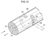
- the rotary valve 84 1 includes a housing 87 fixedly mounted on the cylinder head 20 of the engine body E and having a slide hole 86 circular in cross section and extending parallel to the cam shaft 30, and a columnar valve member 88 rotatably fitted in the slide hole 86 for rotation about an axis of the slide hole 86.
- the timing transmitting means 85 includes a transmitting band 91 such as an endless chain or belt wound, for example, around a timing ring 89 fixed to the cam shaft 30 and a timing ring 90 fixed to the valve member 88, as shown in Fig.12. Moreover, in the stoppage cycle in which two runs of the stoppage subsequent to one run of the operation are repeated as shown in Table 1, the ratio of the outside diameter of the timing ring 90 to the outside diameter of the timing ring 89 is set at 1/3.
- the valve member 88 is provided with an oil supplying passage 92 leading to the solenoid fluid pressure control valve means 58 A , and an oil discharging passage 94 leading to a reservoir of the same type or a different type as or from the reservoirs 60 and 67. Further, an oil supplying groove 95 is provided in an outer periphery of the valve member 88 to lead to the oil supplying passage 92, and an oil discharging groove 96 is also provided in the outer periphery of the valve member 88 to lead to the oil discharging passage 94.
- the oil supplying groove 95 is defined over an extent of approximately 240 degree about an axis of the valve member 88, and the oil discharging groove 96 is defined at a location axially spaced apart from the oil supplying groove 95 in an axial direction of the valve member 88 over an extent of approximately 120 degree excluding the region in which the oil supplying groove 95 is provided.
- an oil passage 97 is provided in the housing 87 to lead to the oil passage 49 in the valve operation/stoppage means 40 1
- a communication groove 98 is also provided in the housing 87 to lead to the oil passage 97, and opens into an inner surface of the slide hole 86.
- the communication groove 98 is defined long along an axis of the slide hole 86, so that it can be put into communication with any of the oil supplying groove 95 and the oil discharging groove 96 in response to the rotation of the valve member 88.
- valve member 88 of the rotary valve 84 1 is rotated one time as shown as (b) in Fig.14 in response to three runs of the rotation shown as (a) in Fig.14.
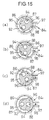
- the valve member 88 Up to a time point t 1 immediately after completion of the first one run of the rotation through a crankshaft angle, the valve member 88 is in a state in which it permits the oil discharging groove 96 to be put into communication with the oil passage 97, as shown in Fig.15A.
- a hydraulic pressure is applied to the hydraulic pressure chamber 41 in the valve operation/stoppage switchover means 40 1 .
- the valve operation/stoppage switchover means 40 1 is switched from the connecting state to the disconnecting state, as shown as (f) in Fig.14.
- the valve member 88 of the rotary valve 84 1 is in a state in which the oil supplying groove 96 is in communication with the oil passage 97, as shown in Fig.15B. Therefore, even at a time of second opening of the intake valve V I , the intake valve V I is left closed and stopped.
- the valve operation/stoppage switchover means 40 1 is switched from the disconnecting state to the connecting state at a time when the intake valve V I in the closed and topped state is stopped, i.e., at a time point t 4 when the free rocker arm 28 abuts against the base-circle portion 34a of the operating cam 34.
- the valve member 88 is returned from a position in which the oil discharging groove 96 has been put into communication with the oil passage 97, as shown in Fig.15D to a position shown in Fig.15A.
- the rotary valve 84 1 mechanically controls the application and releasing of the hydraulic pressure to and from the valve operation/stoppage switchover means 40 1 so that the intake valve V I is stopped two times subsequently to one run of the operation of the intake valve V I .
- a rotary valve 84 1 similar to the above-described rotary valve is connected to a valve operation/stoppage switchover means 40 1 for the exhaust valve V E .
- the exhaust valve V E is also controlled so that it is stopped two times subsequently to one run of operation.
- each of the intake valves V I and the exhaust valves V E in the second, third and fourth cylinders C 2 , C 3 and C 4 is controlled by each of rotary valves 84 2 , 84 3 and 84 4 similar to the rotary valve in the first cylinder C 1 .
- the timing of supplying of the working fluid to each of the valve operation/stoppage switchover means 40 1 , 40 2 , 40 3 and 40 4 in the cylinders C 1 , C 2 , C 3 and C 4 is controlled by each of the rotary valve 84 1 , 84 2 , 84 3 and 84 4 which are mechanically operated in operative association with the crankshaft rotation. Therefore, it is unnecessary to carry out the judgment of the cylinders and moreover, whereas a delay of a signal, a delay of rising of the hydraulic pressure and the like are generated when a control is carried out based on the judgment of the cylinders, it is unnecessary to give such a consideration.
- the single solenoid fluid pressure control valve means 58 A and the single solenoid fluid pressure control valve means 58 B may be provided for the plurality of cylinders and therefore, the number of relatively expensive solenoid valves can be decreased.
- the exhaust valve V E may be closed and stopped after the opening of the intake valve V I , thereby making a smooth removal of a combustion gas difficult, and/or the exhaust valve V E may be opened after closing and stoppage of the intake valve V I to cause a back flow of the combustion gas from the side of the exhaust manifold M E . Accordingly, it is desirable that the timing of application of the hydraulic pressure is controlled by the solenoid fluid pressure control valve means 58 A and 58 B for every cylinders in which such a disadvantage is difficult to be arisen, e.g., for the first and second cylinders C 1 and C 2 as well as for the third and fourth cylinders C 3 and C 4 .
- Fig.16 illustrates a third embodiment of the present invention, wherein portions or components corresponding to those in each of the above-described embodiments are designated by like reference characters.
- a driving rocker arm 27' operatively connected to the intake valve V I , a first free rocker arm 28 adjoining one side of the driving rocker arm 27', and a second free rocker arm 100 adjoining the other side of the driving rocker arm 27' are swingably carried on a rocker arm shaft 26'.
- a cam shaft 30' is integrally provided with a stopping portion 32 which is in sliding contact with the driving rocker arm 27', a first operating cam 34 which is in sliding contact with the first free rocker arm 28, and a second operating cam 101 which is in sliding contact with the second free rocker arm 100.
- the first operating cam 34 has a cam profile corresponding to a higher speed operating range of the engine, while the second operating cam 101 has a cam profile corresponding to a lower speed operating range than that of the first operating cam 34.
- connection switchover means 40 1A is provided between the driving rocker arm 27' and the first free rocker arm 28 and capable of switching the connection and disconnection of the rocker arms 27' and 28 to and from each other.
- a connection switchover means 40 1B is provided between the driving rocker arm 27' and the second free rocker arm 100 and capable of switching the connection and disconnection of the rocker arms 27' and 100 to and from each other.
- Each of the connection switchover means 40 1A and 40 1B has basically the same construction as the valve operation/stoppage switchover means 40 1 in the first embodiment, and is switchable between a connecting state provided upon releasing of the hydraulic pressure, and a disconnecting state provided upon application of the hydraulic pressure.
- the rocker arm shaft 26' includes an oil passage 49 A connected to the connection switchover means 40 1A , and an oil passage 49 B connected to the connection switchover means 40 1B , these oil passages 49 A and 49 B being independently provided in the rocker arm shaft 26'.
- the connection switchover means 40 1A and 40 1B are capable of being independently operated for switching.
- the third embodiment enables following conditions to be switched from one to the other: a condition in which both of the connection switchover means 40 1A and 40 1B are brought into disconnecting states to stop the intake valve V I , a condition in which the connection switchover means 40 1B is brought into the connecting state, while the connection switchover means 40 1A is brought into the disconnecting state, thereby opening and closing the intake valve V I by the second operating cam 101, and a condition in which the connection switchover means 40 1A is brought into the connecting state, while the connection switchover means 40 1B is brought into the disconnecting, thereby opening and closing the intake valve V I by the first operating cam 34.
- Fig.17 illustrates a fourth embodiment of the present invention.
- a driving rocker arm 27'' is swingably carried on a rocker arm shaft 26' between a first free rocker arm 28 which is in sliding contact with the first operating cam 34, and a second free rocker arm 100 which is in sliding contact with the second operating cam 101.
- the driving rocker arm 27'' is operatively connected to a pair of intake valves V I , V I and is in sliding contact with the stopping portion 32.
- a connection switchover means 40 1A is provided between the driving rocker arm 27'' and the first free rocker arm 28 and capable of switching the connection and disconnection of the rocker arms 27'' and 28 to and from each other.
- a connection switchover means 40 1B is provided between the driving rocker arm 27'' and the second free rocker arm 100 and capable of switching the connection and disconnection of the rocker arms 27'' and 100 to and from each other.
- the fourth embodiment enables following conditions to be switched from one to the other: a condition in which the pair of intake valves V I , V I are stopped, a condition in which the pair of intake valves V I , V I are opened and closed by the second operating cam 101, and a condition in which the pair of intake valves V I , V I are opened and closed by the first operating cam 34.
- Fig.18 illustrates a fifth embodiment of the present invention, wherein portions or components corresponding to those in each of the above-described embodiments are designated by like reference characters.
- a rocker arm shaft 26'' includes a first driving rocker arm 27 A to which one of a pair of intake valves V I , V I is operatively connected; a second driving rocker arm 27 B to which the other intake valve V I is operatively connected and which adjoins the first driving rocker arm 27 A ; a first free rocker arm 28 adjoining the first driving rocker arm 27 A on the opposite side from the second driving rocker arm 27 B ; and a second free rocker arm 100 adjoining the second driving rocker arm 27 B on the opposite side from the first driving rocker arm 27 A .
- a cam shaft 30'' is integrally provided with a pair of stopping portions 32, 32 which are in sliding contact with the first and second driving rocker arms 27 A and 27 B , respectively, a first operating cam 34 which is in sliding contact with the first free rocker arm 28, and a second operating cam 101 which is in sliding contact with the second free rocker arm 100.
- a connection switchover means 40 1A is provided between the first driving rocker arm 27 A and the first free rocker arm 28 and capable of switching the connecting and disconnection of the rocker arms 27 A and 28 to and from each other.
- a connection switchover means 40 1B is provided between the second driving rocker arm 27 B and the second free rocker arm 100 and capable of switching the connecting and disconnection of the rocker arms 27 B and 100 to and from each other.
- a connection switchover means 40 1C is provided between both the driving rocker arms 27 A and 27 B and capable of switching the connecting and disconnection of the rocker arms 27 A and 27 B to and from each other.
- connection switchover means 40 A , 40 B and 40 1C has basically the same construction as the valve operation/stoppage switchover means 40 1 in the first embodiment and is switchable between a connecting state provided upon releasing of a hydraulic pressure and a disconnecting state provided upon application of the hydraulic pressure.
- the rocker arm shaft 26 is independently provided with an oil passage 49 A connected to the connection switchover means 40 1A , an oil passage 49 B connected to the connection switchover means 40 1B , and an oil passage 49 C connected to the connection switchover means 40 1C .
- the connection switchover means 40 1A , 40 1B and 40 1C can be independently operated for switching.
- the fifth embodiment enables following conditions to be switched from one to the other: a cylinder-stopped condition in which all the connection switchover means 40 1A , 40 1B and 40 1C are brought into the disconnecting states to stop both of the intake valve V I , V I ; a condition in which the connection switchover means 40 1A is brought into the connecting state, while the connection switchover means 40 1B and 40 1C are brought into the disconnecting states, thereby stopping one of the intake valve V I and opening and closing the other intake valve V I by the second operating cam 101; a condition in which the connection switchover means 40 1A and 40 1B are brought into the connecting states, while the connection switchover means 40 1C is brought into the disconnecting state, thereby opening and closing the one intake valve V I by the first operating cam 34 and opening and closing the other intake valve V I by the second operating cam 101; and a condition in which all the connection switchover means 40 1A , 40 1B and 40 1C are brought into the connecting states to open and close both the intake valves V I , V I
- Fig.19 illustrates a sixth embodiment of the present invention.
- fuel injection valves V FI are provided in an intake manifold M 1 in independent correspondence to the cylinders C 1 , C 2 , C 3 and C 4 as combustion governing means for governing the execution and stoppage of the combustion in the cylinders C 1 , C 2 , C 3 and C 4 .
- the operation of the fuel injection valves V FI is controlled by a control unit 75.
- the control unit 75 controls the operation and stoppage of the fuel injection valves V FI in such a switching manner that the operation and stoppage of the cylinders C 1 , C 2 , C 3 and C 4 are repeated according to a predetermined cylinder stoppage cycle, when the engine is in the cylinder operation-stopped operational state.
- a plurality of control modes with different cylinder stoppage cycles are previously established, and the fuel injection valves V FI are controlled by the control mode selected in accordance with the operational state of the engine.
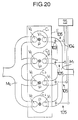
- Fig.20 illustrates a seventh embodiment of the present invention.
- cut-off valves 103 are provided in an intake manifold M 1 in independent correspondence to the cylinders C 1 , C 2 , C 3 and C 4 and capable of cutting off the supplying of an air-fuel mixture to the cylinders C 1 , C 2 , C 3 and C 4 .
- Actuators 104 are connected to cut-off valves 103, respectively.
- the cut-off valve 103 and the actuator 104 constitute a combustion governing means 105 for governing the execution and stoppage of the combustion in each of the cylinders C 1 , C 2 , C 3 and C 4 .
- the operation of the combustion governing means 105 is controlled by a control unit 75.
- control unit 75 the operation and stoppage of the combustion governing means 105 for every cylinder in such a switching manner that the operation and stoppage of all the cylinders are repeated according to a predetermined cylinder stoppage cycle, when the engine is in the cylinder operation-stopped operational state. Any of a plurality of control modes with different cylinder stoppage cycles can be selected in accordance with the operational state of the engine.
- the ignition and stoppage of spark plugs P as combustion governing means for governing the combustion in the cylinders C 1 , C 2 , C 3 and C 4 may be controlled by the control unit 75.
- the present invention is applicable to a 5-cylinder internal combustion engine.
- an internal combustion engine including five cylinders C 1 , C 2 , C 3 , C 4 and C 5 a plurality of control modes, for example, as shown in Table 4 are established, and any one of the control modes is selected in accordance with the operational state of the engine.
- the explosion chance is 1/4 in the first mode, 1/3 in the second mode, and 1/2 in the third mode.
- the present invention is also applicable to a 6-cylinder internal combustion engine.
- an internal combustion engine including six cylinders C 1 , C 2 , C 3 , C 4 , C 5 and C 6 , a plurality of control modes, for example, as shown in Table 5 are established, and any one of the control modes is selected in accordance with the operational state of the engine.
- the explosion chance is 1/2 in the first mode, 1/5 in the second mode, 1/4 in the third mode, and 1/3 in the fourth mode.
- the ignition intervals are equal in the first and second modes, while the ignition intervals are unequal in the third and fourth modes.
- the present invention is applicable not only to 4-cycle internal combustion engine, but also to a 2-cycle internal combustion engine, and also to an internal combustion engine designed so that the stoppage of cylinders is performed by closing and stopping only intake valves V I of intake and exhaust valves V I and V E .
Landscapes
- Engineering & Computer Science (AREA)
- Mechanical Engineering (AREA)
- General Engineering & Computer Science (AREA)
- Chemical & Material Sciences (AREA)
- Combustion & Propulsion (AREA)
- Output Control And Ontrol Of Special Type Engine (AREA)
- Valve Device For Special Equipments (AREA)
Claims (8)
- Verbrennungsmotor mit variabler Zylinderzahl-Steuerung, der ein Verbrennungs-Bestimmungsmittel (40; 105) aufweist, das für jeden einer Mehrzahl von Zylindern (C) angeordnet ist, um die Ausführung und den Stopp der Kraftstoffverbrennung zu bestimmen, derart, dass der Betrieb eines jeden der Zylinder (C) durch einen Stoppbetrieb des Verbrennungs-Bestimmungsmittels (40; 105) gestoppt wird, wobeider Verbrennungsmotor ferner eine Steuereinheit (75) aufweist, um ein Umschalten zwischen einem Normalbetrieb und einem Stoppbetrieb des Verbrennungs-Bestimmungsmittels (40; 105) für jeden der Zylinder (C) derart zu steuern, dass der Betrieb und Stopp jedes Zylinders (C) gemäß einer zuvor eingerichteten Zylinderbetriebs- und -stoppfolge wiederholt wird, die sich von einer Zylinderbetriebs- und -stoppfolge zumindest eines anderen der Zylinder (C) unterscheidet, wenn sich der Motor in einem Zylinderbetrieb-Stopp-Betriebszustand befindet,
dadurch gekennzeichnet,
dass die Steuereinheit (75) in der Lage ist, gemäß dem Betriebszustand des Motors einen einer Mehrzahl von Steuermodi zu wählen, die jeweils eine unterschiedliche Zylinderbetriebs- und -stoppfolge aufweisen, und wobei einer der Steuermodi für jede gesetzte Drehzahl einer Motorkurbelwelle eine Stoppbetriebsfrequenz jedes Zylinders (C) aufweist, die zwischen den mehreren Zylindern unterschiedlich ist. - Verbrennungsmotor mit variabler Zylinderzahl-Steuerung nach Anspruch 1, bei dem in jedem der Zylinder ein jeweiliges Motorventil (VI) angeordnet ist, so dass der Betrieb jedes Zylinders durch Betriebsstopp des in diesem Zylinder angeordneten Motorventils (VI) gestoppt wird, wobeidas Verbrennungs-Bestimmungsmittel ein Ventilbetrieb-und-Stopp-Umschaltmittel (401-4) aufweist, das für die jeweiligen Zylinder vorgesehen und in der Lage ist, den Betrieb und Stopp der Motorventile (VI) unabhängig voneinander umzuschalten, und wobei die Steuereinheit (75) den Betrieb des Ventilbetrieb-und-Stopp-Umschaltmittels (401-4) in dem Zylinderbetrieb-Stopp-Betrebszustand steuert, um zu bewirken, dass das Motorventil (VI) in jedem Zylinder gemäß dem zuvor eingerichteten Motorventilbetriebs- und Stoppsteuermodus wiederholt Betriebs- und Stoppzustände einnimmt, in einer Betriebs- und Stoppfolge, die sich von einer Betriebs- und Stoppfolge in dem Motorventil (VI) zumindest eines anderen Zylinders (C1 - C4) unterscheidet, wenn sich der Motor in dem Zylinderbetrieb-Stopp-Betriebszustand befindet, und wobei in dem Zylinderbetrieb-Stopp-Betriebszustand eine Stoppfrequenz jedes Motorventils (VI) für jede gesetzte Drehzahl der Motorkurbelwelle zwischen den mehreren Zylindern unterschiedlich ist.
- Verbrennungsmotor mit variabler Zylinderzahl-Steuerung nach Anspruch 2, wobei das Ventilbetrieb-und-Stopp-Umschaltmittel (401-4) für jeden der Zylinder (C1 - C4) derart angeordnet ist, dass der Betrieb und Stopp des Motorventils (VI) durch Fluiddruck geschaltet wird, und wobei der Motor ferner Solenoid-Fluiddrucksteuerventilmittel (581-4) aufweist, die unabhängig mit den Ventilbetrieb-und-Stopp-Umschaltmitteln (401) für die jeweiligen Zylinder verbunden sind und die durch die Steuereinheit (75) gesteuert werden.
- Verbrennungsmotor mit variabler Zylinderzahl-Steuerung nach Anspruch 2, wobei das Ventilbetrieb-und-Stopp-Umschaltmittel (401-4) für jeden der Zylinder (C1 - C4) derart angeordnet ist, dass der Betrieb und Stopp des Motorventils (VI) durch Fluiddruck geschaltet wird, und wobei der Motor ferner ein Solenoid-Fluiddrucksteuerventilmittel (581-4) aufweist, das für jeden der Zylinder (C1 - C4) angeordnet ist und durch das Steuermittel (75) gesteuert wird, sowie ein mechanisch betätigtes Ventil (841-4), das zwischen jedem der Solenoid-Fluiddrucksteuerventilmittel (581-4) und jedem der Ventilbetrieb-und-Stopp-Umschaltmittel (401-4) vorgesehen ist, um die Zufuhrzeit des Arbeitsfluids zu jedem der Ventilbetrieb-und-Stopp-Umschaltmittel (401-4) durch einen mechanischen Vorgang in Bezug auf den Drehbetrieb der Kurbelwelle zu bestimmen.
- Verbrennungsmotor mit variabler Zylinderzahl-Steuerung nach Anspruch 1, der ein für jeden der Zylinder jeweils angeordnetes Motorventil aufweist, derart, dass der Betrieb jedes Zylinders (C1-4) durch Betriebsstopp des in diesem Zylinder angeordneten Motorventils (VI) gestoppt wird, wobeidas Verbrennungs-Bestimmungsmittel Ventilbetrieb-und-Stopp-Umschaltmittel (40) aufweist, die für die jeweiligen Zylinder vorgesehen sind und in der Lage sind, den Betrieb und Stopp der Motorventile (VI) unabhängig voneinander umzuschalten, und wobei die Steuereinheit (75) den Betrieb des Ventilbetrieb-und-Stopp-Umschaltmittels (40) in dem Zylinderbetriebs- und Stoppbetriebszustand steuert, um eine vorbestimmte Motorventil-Betriebs- und Stoppfolge für das Motorventil in jedem der Zylinder (C) zu bewirken, wenn sich der Motor in dem Zylinderbetriebs- und Stoppbetriebszustand befindet; und
wobei die Motorventil-Betriebs- und Stoppfolge für jeden der Zylinder (C) gesetzt und derart eingerichtet ist, dass Phasen der Motorventil-Betriebs- und Stoppfolgen für jeden der Zylinder (C) bewirken, dass für jede gesetzte Drehzahl der Motorkurbelwelle eine Stoppfrequenz jedes Motorventils (VI) zwischen den mehreren Zylindern (C) unterschiedlich ist. - Verbrennungsmotor mit variabler Zylinderzahl-Steuerung nach Anspruch 1, der zumindest ein in jedem der Zylinder angeordnetes Einlassmotorventil aufweist, wobei das Verbrennungs-Bestimmungsmittel ein Ventilbetrieb-und-Stopp-Umschaltmittel (40) aufweist, das für jeden der Zylinder (C) vorgesehen ist, wobei das Umschaltmittel (40) in der Lage ist, den Betrieb und Stopp des Einlassmotorventils in den Zylindern unabhängig voneinander umzuschalten, um den Betrieb dieses Zylinders zu stoppen, und wobei die Steuereinheit (75) den Betrieb jedes der Ventilbetrieb-und-Stopp-Umschaltmittel (40) steuert, um zu bewirken, dass jeder der Zylinder (C) periodisch in Betrieb ist und periodisch stoppt, wobei jeder der Zylinder (C) während unterschiedlichen Drehzyklen der Motorkurbelwelle in Betrieb ist und während unterschiedlichen Drehzyklen der Kurbelwelle gestoppt wird, wenn der Motor in dem Zylinderbetrieb-Stopp-Betriebszustand ist, wobei eine Betriebsstoppfrequenz jedes Einlassventils (VI) für jede gesetzte Drehzahl der Motorkurbelwelle zwischen den mehreren Zylindern (C) unterschiedlich ist.
- Verbrennungsmotor mit variabler Zylinderzahl-Steuerung nach Anspruch 2, 5 oder 6, wobei der Motor eine von der Kurbelwelle drehend angetriebene Nockenwelle (30) aufweist, und wobei das Ventilbetrieb-und-Stopp-Umschaltmittel (40) betriebsmäßig zwischen der Nockenwelle (30) und den Motorventilen (VI) vorgesehen ist, um in Antwort auf die Drehung der Nockenwelle (30) einen selektiven Betrieb der Motorventile (VI) zu bewirken.
- Verbrennungsmotor mit variabler Zylinderzahl-Steuerung nach Anspruch 1, wobei das Verbrennungs-Bestimmungsmittel (40) ein Motoreinlassventil (VI) in jedem Zylinder (C) sowie Ventilbetätigungsmittel (40) zum selektiven Betätigen oder Stoppen des Betriebs jedes Einlassmotorventils (VI) umfasst, wobei der Motor eine von der Kurbelwelle drehhend angetriebene Nockenwelle (30) aufweist, und wobei die Ventilbetätigungsmittel (40) betriebsmäßig zwischen der Nockenwelle (30) und jedem Einlassmotorventil (VI) vorgesehen sind, um den Betrieb jedes Motorventils (VI) durch und in Antwort auf die Drehung der Nockenwelle (30) selektiv zu bewirken.
Priority Applications (1)
| Application Number | Priority Date | Filing Date | Title |
|---|---|---|---|
| EP99115260A EP0955458B1 (de) | 1994-09-20 | 1995-06-21 | Brennkraftmaschine mit Steuerung der Zahl der aktiven Zylinder |
Applications Claiming Priority (3)
| Application Number | Priority Date | Filing Date | Title |
|---|---|---|---|
| JP22446094 | 1994-09-20 | ||
| JP22446094A JP3358887B2 (ja) | 1994-09-20 | 1994-09-20 | 気筒数制御内燃機関 |
| JP224460/94 | 1994-09-20 |
Related Child Applications (1)
| Application Number | Title | Priority Date | Filing Date |
|---|---|---|---|
| EP99115260A Division EP0955458B1 (de) | 1994-09-20 | 1995-06-21 | Brennkraftmaschine mit Steuerung der Zahl der aktiven Zylinder |
Publications (3)
| Publication Number | Publication Date |
|---|---|
| EP0703357A2 EP0703357A2 (de) | 1996-03-27 |
| EP0703357A3 EP0703357A3 (de) | 1996-07-24 |
| EP0703357B1 true EP0703357B1 (de) | 2000-06-14 |
Family
ID=16814134
Family Applications (2)
| Application Number | Title | Priority Date | Filing Date |
|---|---|---|---|
| EP99115260A Expired - Lifetime EP0955458B1 (de) | 1994-09-20 | 1995-06-21 | Brennkraftmaschine mit Steuerung der Zahl der aktiven Zylinder |
| EP95109646A Expired - Lifetime EP0703357B1 (de) | 1994-09-20 | 1995-06-21 | Brennkraftmaschine mit Steuerung der Zahl der aktiven Zylinder |
Family Applications Before (1)
| Application Number | Title | Priority Date | Filing Date |
|---|---|---|---|
| EP99115260A Expired - Lifetime EP0955458B1 (de) | 1994-09-20 | 1995-06-21 | Brennkraftmaschine mit Steuerung der Zahl der aktiven Zylinder |
Country Status (4)
| Country | Link |
|---|---|
| US (1) | US5636609A (de) |
| EP (2) | EP0955458B1 (de) |
| JP (1) | JP3358887B2 (de) |
| DE (2) | DE69520160T2 (de) |
Families Citing this family (28)
| Publication number | Priority date | Publication date | Assignee | Title |
|---|---|---|---|---|
| US6647954B2 (en) * | 1997-11-17 | 2003-11-18 | Diesel Engine Retarders, Inc. | Method and system of improving engine braking by variable valve actuation |
| US5975052A (en) * | 1998-01-26 | 1999-11-02 | Moyer; David F. | Fuel efficient valve control |
| US6273208B1 (en) | 1998-10-15 | 2001-08-14 | Darrel R. Sand | Variable displacement vehicle engine and solid torque tube drive train |
| DE19905364C1 (de) | 1999-02-10 | 2000-08-03 | Daimler Chrysler Ag | Verfahren zum Betrieb einer Brennkraftmaschine mit variablen Gaswechselsteuerzeiten |
| DE19941692A1 (de) * | 1999-09-01 | 2001-03-15 | Siemens Ag | Verfahren zur schnellen Reduktion des Antriebsmoments |
| DE10055595A1 (de) * | 2000-11-09 | 2002-05-29 | Ina Schaeffler Kg | Verfahren und Vorrichtung zur Zylinderabschaltung bei Verbrennungsmotoren |
| JP2002227665A (ja) * | 2001-01-30 | 2002-08-14 | Nissan Motor Co Ltd | 内燃機関の弁停止機構の油圧制御装置 |
| JP4202166B2 (ja) * | 2003-03-26 | 2008-12-24 | 本田技研工業株式会社 | 多気筒エンジン |
| US7007646B2 (en) * | 2003-09-18 | 2006-03-07 | Mitsubishi Jidosha Kogyo Kabushiki Kaisha | Valve gear with cylinder suspending mechanism of an internal combustion engine |
| US20050188930A1 (en) * | 2004-02-18 | 2005-09-01 | Best Richard R. | Valve deactivation device |
| JP4327050B2 (ja) * | 2004-09-07 | 2009-09-09 | 本田技研工業株式会社 | 気筒休止内燃機関 |
| DE102005006491B4 (de) * | 2005-02-12 | 2008-09-04 | Audi Ag | Verfahren und Vorrichtung zur Ansteuerung von Nockenprofilen einer Nockenwelle einer mehrzylindrigen Brennkraftmaschine |
| JP4789881B2 (ja) | 2007-06-29 | 2011-10-12 | 本田技研工業株式会社 | 気筒休止機構付き水冷式多気筒内燃機関の冷却制御装置 |
| JP5139112B2 (ja) * | 2008-02-19 | 2013-02-06 | ヤマハ発動機株式会社 | エンジン |
| JP5139113B2 (ja) * | 2008-02-19 | 2013-02-06 | ヤマハ発動機株式会社 | 可変動弁装置 |
| US8616181B2 (en) | 2008-07-11 | 2013-12-31 | Tula Technology, Inc. | Internal combustion engine control for improved fuel efficiency |
| US9020735B2 (en) | 2008-07-11 | 2015-04-28 | Tula Technology, Inc. | Skip fire internal combustion engine control |
| US9664130B2 (en) | 2008-07-11 | 2017-05-30 | Tula Technology, Inc. | Using cylinder firing history for combustion control in a skip fire engine |
| US8336521B2 (en) | 2008-07-11 | 2012-12-25 | Tula Technology, Inc. | Internal combustion engine control for improved fuel efficiency |
| US8701628B2 (en) | 2008-07-11 | 2014-04-22 | Tula Technology, Inc. | Internal combustion engine control for improved fuel efficiency |
| US20100050993A1 (en) * | 2008-08-29 | 2010-03-04 | Yuanping Zhao | Dynamic Cylinder Deactivation with Residual Heat Recovery |
| JP4702430B2 (ja) * | 2008-10-20 | 2011-06-15 | トヨタ自動車株式会社 | 内燃機関の可変動弁機構 |
| JP2010264652A (ja) | 2009-05-14 | 2010-11-25 | Fujifilm Corp | 造形物の製造方法及び製造装置 |
| US8511281B2 (en) | 2009-07-10 | 2013-08-20 | Tula Technology, Inc. | Skip fire engine control |
| FR3008137B1 (fr) * | 2013-07-04 | 2015-08-07 | Peugeot Citroen Automobiles Sa | Ensemble d'un systeme a arbres a cames et d'un distributeur rotatif hydraulique pour un moteur |
| US9976500B2 (en) * | 2014-10-20 | 2018-05-22 | Ford Global Technologies, Llc | Method and system for selective cylinder deactivation |
| JP6900783B2 (ja) * | 2017-05-22 | 2021-07-07 | 株式会社デンソー | 燃料噴射制御装置 |
| CN115066545B (zh) | 2020-01-24 | 2024-01-05 | 康明斯有限公司 | 用于修改气缸停用策略的动态气缸停用寿命因子 |
Family Cites Families (13)
| Publication number | Priority date | Publication date | Assignee | Title |
|---|---|---|---|---|
| US4146006A (en) * | 1976-09-17 | 1979-03-27 | Arthur Garabedian | Fuel injection split engine |
| US4584974A (en) * | 1982-07-27 | 1986-04-29 | Nissan Motor Co., Ltd. | Valve operation changing system of internal combustion engine |
| JPS5974343A (ja) * | 1982-10-19 | 1984-04-26 | Mazda Motor Corp | 3気筒エンジンの気筒数制御装置 |
| JPS59103934A (ja) * | 1982-12-07 | 1984-06-15 | Mitsuwa Seiki Co Ltd | 内燃機関の燃料供給装置 |
| JPS608407A (ja) * | 1983-06-29 | 1985-01-17 | Honda Motor Co Ltd | 内燃機関の弁作動制御装置 |
| DE3623040A1 (de) * | 1986-07-09 | 1988-01-14 | Bosch Gmbh Robert | Verfahren zur kraftstoffeinspritzung |
| US4790274A (en) * | 1986-07-30 | 1988-12-13 | Honda Giken Kogyo Kabushiki Kaisha | Valve operating mechanism for internal combustion engine |
| JPS6357806A (ja) * | 1986-08-27 | 1988-03-12 | Honda Motor Co Ltd | 内燃機関の動弁装置 |
| JPH02123212A (ja) * | 1988-10-31 | 1990-05-10 | Isuzu Motors Ltd | バルブ制御装置 |
| US4991558A (en) * | 1989-01-03 | 1991-02-12 | Siemens Automotive L.P. | Idle and off-idle operation of a two-stroke fuel-injected multi-cylinder internal combustion engine |
| JPH066884B2 (ja) * | 1989-08-03 | 1994-01-26 | 本田技研工業株式会社 | 内燃機関の動弁装置 |
| JP2809005B2 (ja) * | 1992-09-17 | 1998-10-08 | 日産自動車株式会社 | 内燃機関の可変動弁装置 |
| US5377631A (en) * | 1993-09-20 | 1995-01-03 | Ford Motor Company | Skip-cycle strategies for four cycle engine |
-
1994
- 1994-09-20 JP JP22446094A patent/JP3358887B2/ja not_active Expired - Fee Related
-
1995
- 1995-06-07 US US08/475,881 patent/US5636609A/en not_active Expired - Lifetime
- 1995-06-21 EP EP99115260A patent/EP0955458B1/de not_active Expired - Lifetime
- 1995-06-21 DE DE69520160T patent/DE69520160T2/de not_active Expired - Fee Related
- 1995-06-21 DE DE69517484T patent/DE69517484T2/de not_active Expired - Fee Related
- 1995-06-21 EP EP95109646A patent/EP0703357B1/de not_active Expired - Lifetime
Also Published As
| Publication number | Publication date |
|---|---|
| EP0955458A1 (de) | 1999-11-10 |
| JP3358887B2 (ja) | 2002-12-24 |
| DE69520160D1 (de) | 2001-03-29 |
| EP0955458B1 (de) | 2001-02-21 |
| US5636609A (en) | 1997-06-10 |
| DE69517484T2 (de) | 2000-10-26 |
| EP0703357A3 (de) | 1996-07-24 |
| DE69517484D1 (de) | 2000-07-20 |
| EP0703357A2 (de) | 1996-03-27 |
| JPH0893516A (ja) | 1996-04-09 |
| DE69520160T2 (de) | 2001-06-07 |
Similar Documents
| Publication | Publication Date | Title |
|---|---|---|
| EP0703357B1 (de) | Brennkraftmaschine mit Steuerung der Zahl der aktiven Zylinder | |
| US4534323A (en) | Valve operation changing system of internal combustion engine | |
| US6257176B1 (en) | Variable cycle internal combustion engine and controller thereof | |
| JP2843614B2 (ja) | 2サイクルディーゼルエンジン | |
| JPH07208221A (ja) | 可変排気量内燃機関内の複数シリンダを同期的に活性化するシリンダ同期活性化装置 | |
| EP0671550B1 (de) | Ventilsteuervorrichtung für Brennkraftmaschine | |
| CA1229537A (en) | Internal combustion engine | |
| US5259357A (en) | Ignition system for internal combustion engine | |
| US6237559B1 (en) | Cylinder deactivation via exhaust valve deactivation and intake cam retard | |
| CA2298986A1 (en) | A decompression device of a four-stroke cycle internal combustion engine | |
| GB2119853A (en) | Four-cylinder I.C. engine operable with two effective cylinders | |
| US4399784A (en) | Internal combustion engine | |
| CN106050387B (zh) | 用于活塞冷却的系统和方法 | |
| US5273006A (en) | Deactivatable valve control arrangement for internal combustion engines | |
| AU2003269033B2 (en) | Hydraulic valve actuator for reciprocating engine | |
| KR100258047B1 (ko) | 내연 기관의 밸브 특성 제어 장치 | |
| US10954869B1 (en) | System and method to reduce engine hydrocarbon emissions | |
| US10364712B2 (en) | System for variable actuation of a valve of an internal-combustion engine | |
| WO1982003891A1 (en) | Adjustable fuel injection apparatus for dual fuel engines | |
| JP2004332824A (ja) | クランク角位相可変装置 | |
| JPS59115410A (ja) | 内燃機関の弁作動切換装置 | |
| JPS5923007A (ja) | 内燃機関の弁作動切換装置 | |
| JPS62131932A (ja) | 内燃機関の可変ストロ−ク装置 | |
| JPS59122747A (ja) | 気筒数制御機関 |
Legal Events
| Date | Code | Title | Description |
|---|---|---|---|
| PUAI | Public reference made under article 153(3) epc to a published international application that has entered the european phase |
Free format text: ORIGINAL CODE: 0009012 |
|
| AK | Designated contracting states |
Kind code of ref document: A2 Designated state(s): DE FR GB |
|
| PUAL | Search report despatched |
Free format text: ORIGINAL CODE: 0009013 |
|
| AK | Designated contracting states |
Kind code of ref document: A3 Designated state(s): DE FR GB |
|
| 17P | Request for examination filed |
Effective date: 19970122 |
|
| 17Q | First examination report despatched |
Effective date: 19970227 |
|
| GRAG | Despatch of communication of intention to grant |
Free format text: ORIGINAL CODE: EPIDOS AGRA |
|
| GRAG | Despatch of communication of intention to grant |
Free format text: ORIGINAL CODE: EPIDOS AGRA |
|
| GRAH | Despatch of communication of intention to grant a patent |
Free format text: ORIGINAL CODE: EPIDOS IGRA |
|
| GRAH | Despatch of communication of intention to grant a patent |
Free format text: ORIGINAL CODE: EPIDOS IGRA |
|
| GRAA | (expected) grant |
Free format text: ORIGINAL CODE: 0009210 |
|
| AK | Designated contracting states |
Kind code of ref document: B1 Designated state(s): DE FR GB |
|
| PG25 | Lapsed in a contracting state [announced via postgrant information from national office to epo] |
Ref country code: FR Free format text: LAPSE BECAUSE OF FAILURE TO SUBMIT A TRANSLATION OF THE DESCRIPTION OR TO PAY THE FEE WITHIN THE PRESCRIBED TIME-LIMIT Effective date: 20000614 |
|
| REF | Corresponds to: |
Ref document number: 69517484 Country of ref document: DE Date of ref document: 20000720 |
|
| EN | Fr: translation not filed | ||
| PLBE | No opposition filed within time limit |
Free format text: ORIGINAL CODE: 0009261 |
|
| STAA | Information on the status of an ep patent application or granted ep patent |
Free format text: STATUS: NO OPPOSITION FILED WITHIN TIME LIMIT |
|
| 26N | No opposition filed | ||
| REG | Reference to a national code |
Ref country code: GB Ref legal event code: IF02 |
|
| PGFP | Annual fee paid to national office [announced via postgrant information from national office to epo] |
Ref country code: GB Payment date: 20040616 Year of fee payment: 10 |
|
| PGFP | Annual fee paid to national office [announced via postgrant information from national office to epo] |
Ref country code: DE Payment date: 20040701 Year of fee payment: 10 |
|
| PG25 | Lapsed in a contracting state [announced via postgrant information from national office to epo] |
Ref country code: GB Free format text: LAPSE BECAUSE OF NON-PAYMENT OF DUE FEES Effective date: 20050621 |
|
| PG25 | Lapsed in a contracting state [announced via postgrant information from national office to epo] |
Ref country code: DE Free format text: LAPSE BECAUSE OF NON-PAYMENT OF DUE FEES Effective date: 20060103 |
|
| GBPC | Gb: european patent ceased through non-payment of renewal fee |
Effective date: 20050621 |