EP0703365A2 - Compresseur à vis - Google Patents
Compresseur à vis Download PDFInfo
- Publication number
- EP0703365A2 EP0703365A2 EP95111798A EP95111798A EP0703365A2 EP 0703365 A2 EP0703365 A2 EP 0703365A2 EP 95111798 A EP95111798 A EP 95111798A EP 95111798 A EP95111798 A EP 95111798A EP 0703365 A2 EP0703365 A2 EP 0703365A2
- Authority
- EP
- European Patent Office
- Prior art keywords
- compressor
- pressure
- housing
- rotor
- screw
- Prior art date
- Legal status (The legal status is an assumption and is not a legal conclusion. Google has not performed a legal analysis and makes no representation as to the accuracy of the status listed.)
- Withdrawn
Links
- 230000002441 reversible effect Effects 0.000 claims abstract 2
- 238000007906 compression Methods 0.000 claims description 12
- 230000006835 compression Effects 0.000 claims description 11
- 230000001105 regulatory effect Effects 0.000 claims 1
- 238000006073 displacement reaction Methods 0.000 description 7
- 239000000243 solution Substances 0.000 description 2
- 238000009825 accumulation Methods 0.000 description 1
- 230000004323 axial length Effects 0.000 description 1
- 239000003637 basic solution Substances 0.000 description 1
- 230000000694 effects Effects 0.000 description 1
- 230000010006 flight Effects 0.000 description 1
- 231100001261 hazardous Toxicity 0.000 description 1
- 230000033001 locomotion Effects 0.000 description 1
- 238000000034 method Methods 0.000 description 1
- 238000007789 sealing Methods 0.000 description 1
- 125000006850 spacer group Chemical group 0.000 description 1
- 230000001960 triggered effect Effects 0.000 description 1
Images


Classifications
-
- F—MECHANICAL ENGINEERING; LIGHTING; HEATING; WEAPONS; BLASTING
- F04—POSITIVE - DISPLACEMENT MACHINES FOR LIQUIDS; PUMPS FOR LIQUIDS OR ELASTIC FLUIDS
- F04C—ROTARY-PISTON, OR OSCILLATING-PISTON, POSITIVE-DISPLACEMENT MACHINES FOR LIQUIDS; ROTARY-PISTON, OR OSCILLATING-PISTON, POSITIVE-DISPLACEMENT PUMPS
- F04C29/00—Component parts, details or accessories of pumps or pumping installations, not provided for in groups F04C18/00 - F04C28/00
- F04C29/0021—Systems for the equilibration of forces acting on the pump
- F04C29/0035—Equalization of pressure pulses
Definitions
- the invention relates to a screw compressor according to the preamble of claim 1.
- Another goal is the compressor control at partial load and idle.
- This solution is based on the idea of the maximum achievable Limit the compressor end pressure from the outset by means of a pressure relief measure that is set to a corresponding maximum pressure limit.
- the pressure-side axial sealing of the compression space formed by the screw flanks of the runners takes place in that the relevant end faces of the runners have as small and therefore a tight end face gap with the associated end wall of the compressor housing, in which the outlet opening for the gas compressed by the runners is provided .
- the measure according to claim 2 makes it possible to limit the achievable compression pressure by deliberately temporarily enlarging the end face gap. Specifically, this is achieved according to the teaching of this claim in that the axial mounting of at least one of the runners is designed to be displaceable, in such a way that an enlargement of the end face gap is triggered by an axial displacement of at least one of the runners when a predetermined final compression limit pressure is exceeded. With an enlarged end face gap, the compressor delivers practically in the short circuit, whereby the maximum achievable compression pressure must inevitably remain low.
- the maximum possible end face gap widening depends on that on the compressor suction side between the housing end wall there and the adjacent end faces of the rotor. Because only by the amount of this game is a shift of the main runner and thus an increase in face-side gap possible on the pressure side. In contrast to the pressure-side end face gap, the suction-side gap in the compressor mode is not particularly narrow because there are no significant pressure differences over the circumference of the rotor.
- an axial displacement of the thrust bearing in the direction of an increase in the pressure side can be exceeded if an axial force exerted by the rotor is exceeded reach the end face gap at least of the rotor.
- the axially compliant intermediate piece must fall back below the specified axial force limit value of the rotor back to the state by axial enlargement in which the pressure-side face play is its minimum set for normal operation of the compressor Has value.
- the resilient part causing the axial displacement of the axial bearing of the rotor of the compressor can be a spring, in particular a plate spring.
- the part which is axially introduced between the axial bearing and the compressor housing and which can be changed in terms of its axial extent is a spring
- the axial displacement of the rotor which increases the end face gap increases automatically when a certain predetermined axial force of the rotor is exceeded.
- the rotor then returns to its normal axial operating position with the smallest possible pressure-side end face gap.
- a part that is controllable in its axial extent from the outside can also be used.
- the axial displacement of at least one of the rotors can be controlled from the outside via this built-in part.
- the controllable part can be, for example, a ring which can be changed hydraulically in its axial length.
- a resilient element can also be provided on the rotor, between the axial bearing and the axial boundary of the bearing, as shown in FIG. 1a.
- an overpressure within the compressor housing which is hazardous to the component is prevented by the fact that in the pressure-side housing end wall at one of the outlet opening a pressure relief valve is provided for the compressed gas adjacent point, where the final compression has not yet been reached.
- This can be designed according to claim 6 so that it can be controlled from the outside by means of auxiliary energy.
- additional relief is achieved, especially if a connection can be made to the suction side.
- the internal compression of the compressor can be reduced or completely eliminated.
- valve to the end face of the housing makes it possible to effectively avoid both damage space and a connection between the tooth gaps in the case of wide rotor teeth, as are usually found on the main rotor.
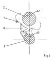
- a compressor housing 1 consisting of rotor housing 1a, inflow housing 1b, cover 1c, spacer ring 1d, a main rotor 2 and a secondary rotor 3 are axially and radially fixed parallel to one another as a pair of rotors.
- This disc spring 6 is designed with respect to its spring force so that it presses the axial bearing 5 with its axial side facing away from the rotor 2 and 3 against the relevant support surface of the compressor housing 1. That is radially outside Axial bearing 5 is not fixed in the compressor housing 1. If the axial force loading the main rotor 2 exceeds a predetermined limit value, the plate spring 6 yields under this force, as a result of which the main rotor 2 is simultaneously displaced towards the inlet side of the compressor housing 1.
- an additional resilient element for example a plate spring 6, can again be provided here at the same location of the axial bearing 5 there. Since an axial force load by the secondary rotor 3 in the compressor mode is lower than that of the main rotor 2, the two resilient elements, e.g. B. disc springs 6 may be designed differently in terms of force. If the response behavior of the two springs 6 to a triggering of an axial displacement of the respective rotor 2, 3 were actually different, this would in principle be irrelevant for the function of the invention. This is because it is sufficient for at least one of the rotors 2 to be axially displaced when a predetermined compression end pressure is exceeded. Because then the desired compression shortage already comes about. By appropriate displacement of the other rotor 3, it is only enlarged.
- the pressure limitation is achieved in a similar manner as in the described embodiment according to FIG. 1. If a predetermined pressure limit is exceeded, the runners - both or only one - are axially displaced in that the resilient element 6 between the bearing and the rotor end its elasticity is deformed so that its length changes. As soon as the pressure falls below the limit value again, the resilient element 6 leads the runners back to the original position. As a result, the end face gap again takes on the small size that is necessary for the compression process. In the example shown here, the spring washer is preloaded between the rings 7b and 7c. This prevents axial movement of the rotor as long as the pressure and thus the axial force are less than the specified limit values.
- the limitation of the compressor end pressure to a certain limit value is achieved by the provision of a pressure relief valve 7 in the end wall 4 of the compressor housing 1.
- the position of the opening of this valve 7 is designed in the end wall 4 with respect to the compressor outlet opening 8 so that the full pressure peak is not yet present at the valve 7 opening.
- a predetermined pressure limit value as a whole cannot be exceeded.
- the direction of rotation of the two runners 2 and 3 is indicated in FIG. 2 with the arrows A2 and A3, in each case with reference to the central axis of the respective rotor 2, 3.
Landscapes
- Engineering & Computer Science (AREA)
- Mechanical Engineering (AREA)
- General Engineering & Computer Science (AREA)
- Applications Or Details Of Rotary Compressors (AREA)
Applications Claiming Priority (2)
| Application Number | Priority Date | Filing Date | Title |
|---|---|---|---|
| DE4432518 | 1994-09-13 | ||
| DE19944432518 DE4432518A1 (de) | 1994-09-13 | 1994-09-13 | Schraubenverdichter |
Publications (2)
| Publication Number | Publication Date |
|---|---|
| EP0703365A2 true EP0703365A2 (fr) | 1996-03-27 |
| EP0703365A3 EP0703365A3 (fr) | 1997-01-08 |
Family
ID=6528063
Family Applications (1)
| Application Number | Title | Priority Date | Filing Date |
|---|---|---|---|
| EP95111798A Withdrawn EP0703365A3 (fr) | 1994-09-13 | 1995-07-27 | Compresseur à vis |
Country Status (2)
| Country | Link |
|---|---|
| EP (1) | EP0703365A3 (fr) |
| DE (1) | DE4432518A1 (fr) |
Families Citing this family (1)
| Publication number | Priority date | Publication date | Assignee | Title |
|---|---|---|---|---|
| DE29904411U1 (de) * | 1999-03-10 | 2000-07-20 | GHH-RAND Schraubenkompressoren GmbH & Co. KG, 46145 Oberhausen | Schraubenkompressor |
Family Cites Families (7)
| Publication number | Priority date | Publication date | Assignee | Title |
|---|---|---|---|---|
| FR601691A (fr) * | 1925-08-05 | 1926-03-05 | Perfectionnements aux pompes rotatives, moteurs, compteurs, etc. | |
| DE890115C (de) * | 1951-07-01 | 1953-09-17 | Hartmann A G Maschf | Einrichtung zur Einstellung des Axialspiels von Drehkolben, Geblaeselaeufern od. dgl. in ihrem Gehaeuse |
| US3388854A (en) * | 1966-06-23 | 1968-06-18 | Atlas Copco Ab | Thrust balancing in rotary machines |
| US3809510A (en) * | 1973-03-22 | 1974-05-07 | Philco Ford Corp | Combination pressure relief and anti-slugging valve for a screw compressor |
| DE3434694A1 (de) * | 1984-09-21 | 1986-04-10 | Bitzer Kühlmaschinenbau GmbH & Co KG, 7032 Sindelfingen | Schraubenverdichter fuer gasfoermige medien |
| SE461052B (sv) * | 1988-04-25 | 1989-12-18 | Svenska Rotor Maskiner Ab | Lyftventil vid en skruvrotormaskin |
| DE9015876U1 (de) * | 1990-03-20 | 1991-02-07 | Mannesmann AG, 4000 Düsseldorf | Wälzlagerung einer Rotorwelle eines Schraubenverdichters |
-
1994
- 1994-09-13 DE DE19944432518 patent/DE4432518A1/de not_active Withdrawn
-
1995
- 1995-07-27 EP EP95111798A patent/EP0703365A3/fr not_active Withdrawn
Non-Patent Citations (1)
| Title |
|---|
| None |
Also Published As
| Publication number | Publication date |
|---|---|
| DE4432518A1 (de) | 1996-03-14 |
| EP0703365A3 (fr) | 1997-01-08 |
Similar Documents
| Publication | Publication Date | Title |
|---|---|---|
| DE3912255C2 (de) | Rotationsverdichter zur Verdichtung von Kältemittel | |
| DE3641226C2 (fr) | ||
| DE2939945C2 (fr) | ||
| EP0750720B1 (fr) | Turbomachine avec piston d'allegement | |
| DE69212222T2 (de) | Spiralverdrängungsanlage für Fluid mit Mengenregelungeinrichtung | |
| DE69105951T2 (de) | Schraubenkolbenmaschine mit schubausgleichsmitteln. | |
| DE69922622T2 (de) | Spiralverdichter | |
| DE69002216T2 (de) | Spiralmaschine mit Gegendrehrichtungsschutz. | |
| DE69827553T2 (de) | Turbomolekularpumpe | |
| DE3319000C2 (fr) | ||
| EP2143953B1 (fr) | Groupe motopompe | |
| EP2212587B1 (fr) | Dispositif d'accouplement hydrodynamique | |
| DE2308265A1 (de) | Rotations- bzw. drehkolbenverdichter anlage mit oelkreislauf und ventilanordnungen | |
| DE2134994A1 (de) | Zweistufige außenachsige Drehkolbenma schine fur elastische Arbeitsmedien | |
| DE2553222C3 (de) | Regelbarer Schraubenverdichter | |
| WO2015074903A1 (fr) | Dispositif de décharge | |
| EP0666422B1 (fr) | Paliers et système d'entraînement pour les rotors d'un compresseur à vis | |
| DE2848514C2 (de) | Pumpenanordnung | |
| DE60208730T2 (de) | Verdichter mit Überdruckventil | |
| EP0231429A2 (fr) | Pompe à engrenages | |
| WO2004109117A1 (fr) | Pompe centrifuge multi-etagee | |
| DE3438049A1 (de) | Stroemungsmaschine in spiralbauweise | |
| EP0703365A2 (fr) | Compresseur à vis | |
| DE60300490T2 (de) | Vakuumpumpe | |
| DE4425406C2 (de) | Abstützkonstruktion für eine Drehwelle eines Kompressors |
Legal Events
| Date | Code | Title | Description |
|---|---|---|---|
| PUAI | Public reference made under article 153(3) epc to a published international application that has entered the european phase |
Free format text: ORIGINAL CODE: 0009012 |
|
| AK | Designated contracting states |
Kind code of ref document: A2 Designated state(s): DE FR IT SE |
|
| PUAL | Search report despatched |
Free format text: ORIGINAL CODE: 0009013 |
|
| AK | Designated contracting states |
Kind code of ref document: A3 Designated state(s): DE FR IT SE |
|
| 17P | Request for examination filed |
Effective date: 19970606 |
|
| RAP1 | Party data changed (applicant data changed or rights of an application transferred) |
Owner name: COMPAIR MAHLE GMBH |
|
| STAA | Information on the status of an ep patent application or granted ep patent |
Free format text: STATUS: THE APPLICATION IS DEEMED TO BE WITHDRAWN |
|
| 18D | Application deemed to be withdrawn |
Effective date: 20000201 |