EP0703371A1 - Vorrichtung zur Befestigung einer Anordnung an einer Säule, insbesondere für die Befestigung einer elektrischen Schaltvorrichtung an einer Kraftfahrzeuglenksäule - Google Patents
Vorrichtung zur Befestigung einer Anordnung an einer Säule, insbesondere für die Befestigung einer elektrischen Schaltvorrichtung an einer Kraftfahrzeuglenksäule Download PDFInfo
- Publication number
- EP0703371A1 EP0703371A1 EP95402102A EP95402102A EP0703371A1 EP 0703371 A1 EP0703371 A1 EP 0703371A1 EP 95402102 A EP95402102 A EP 95402102A EP 95402102 A EP95402102 A EP 95402102A EP 0703371 A1 EP0703371 A1 EP 0703371A1
- Authority
- EP
- European Patent Office
- Prior art keywords
- column
- axis
- assembly
- collar
- corner
- Prior art date
- Legal status (The legal status is an assumption and is not a legal conclusion. Google has not performed a legal analysis and makes no representation as to the accuracy of the status listed.)
- Granted
Links
Images


Classifications
-
- B—PERFORMING OPERATIONS; TRANSPORTING
- B62—LAND VEHICLES FOR TRAVELLING OTHERWISE THAN ON RAILS
- B62D—MOTOR VEHICLES; TRAILERS
- B62D1/00—Steering controls, i.e. means for initiating a change of direction of the vehicle
- B62D1/02—Steering controls, i.e. means for initiating a change of direction of the vehicle vehicle-mounted
- B62D1/16—Steering columns
-
- B—PERFORMING OPERATIONS; TRANSPORTING
- B60—VEHICLES IN GENERAL
- B60K—ARRANGEMENT OR MOUNTING OF PROPULSION UNITS OR OF TRANSMISSIONS IN VEHICLES; ARRANGEMENT OR MOUNTING OF PLURAL DIVERSE PRIME-MOVERS IN VEHICLES; AUXILIARY DRIVES FOR VEHICLES; INSTRUMENTATION OR DASHBOARDS FOR VEHICLES; ARRANGEMENTS IN CONNECTION WITH COOLING, AIR INTAKE, GAS EXHAUST OR FUEL SUPPLY OF PROPULSION UNITS IN VEHICLES
- B60K35/00—Instruments specially adapted for vehicles; Arrangement of instruments in or on vehicles
- B60K35/50—Instruments characterised by their means of attachment to or integration in the vehicle
-
- F—MECHANICAL ENGINEERING; LIGHTING; HEATING; WEAPONS; BLASTING
- F16—ENGINEERING ELEMENTS AND UNITS; GENERAL MEASURES FOR PRODUCING AND MAINTAINING EFFECTIVE FUNCTIONING OF MACHINES OR INSTALLATIONS; THERMAL INSULATION IN GENERAL
- F16B—DEVICES FOR FASTENING OR SECURING CONSTRUCTIONAL ELEMENTS OR MACHINE PARTS TOGETHER, e.g. NAILS, BOLTS, CIRCLIPS, CLAMPS, CLIPS OR WEDGES; JOINTS OR JOINTING
- F16B2/00—Friction-grip releasable fastenings
- F16B2/02—Clamps, i.e. with gripping action effected by positive means other than the inherent resistance to deformation of the material of the fastening
- F16B2/06—Clamps, i.e. with gripping action effected by positive means other than the inherent resistance to deformation of the material of the fastening external, i.e. with contracting action
- F16B2/08—Clamps, i.e. with gripping action effected by positive means other than the inherent resistance to deformation of the material of the fastening external, i.e. with contracting action using bands
-
- F—MECHANICAL ENGINEERING; LIGHTING; HEATING; WEAPONS; BLASTING
- F16—ENGINEERING ELEMENTS AND UNITS; GENERAL MEASURES FOR PRODUCING AND MAINTAINING EFFECTIVE FUNCTIONING OF MACHINES OR INSTALLATIONS; THERMAL INSULATION IN GENERAL
- F16B—DEVICES FOR FASTENING OR SECURING CONSTRUCTIONAL ELEMENTS OR MACHINE PARTS TOGETHER, e.g. NAILS, BOLTS, CIRCLIPS, CLAMPS, CLIPS OR WEDGES; JOINTS OR JOINTING
- F16B2/00—Friction-grip releasable fastenings
- F16B2/02—Clamps, i.e. with gripping action effected by positive means other than the inherent resistance to deformation of the material of the fastening
- F16B2/14—Clamps, i.e. with gripping action effected by positive means other than the inherent resistance to deformation of the material of the fastening using wedges
Definitions
- the present invention relates to the field of systems for fixing an assembly to a column.
- the present invention applies in particular to the fixing of a switching / control assembly of electrical equipment, on a motor vehicle steering column.
- the most conventional technique for fixing an electrical switch plate on a motor vehicle steering column consists of clamping on the column, using a conventional collar, a split barrel axially molded with the switch plate.
- the present invention now aims to improve the known prior fastening systems.
- a system for fixing an assembly to a column comprising a collar adapted to surround the column, a structure linked to the assembly, placed inside the collar and which surrounds the at least partially the column and a corner designed to be placed between the collar and said structure, and thus move the collar radially relative to the axis of the column to tighten the collar and the assembly relative to the column when the corner is moved in a general direction parallel to the axis of the column.
- the faces of the wedge resting respectively on the collar and on said structure of the assembly are symmetrical so that these faces can be reversed.
- the structure linked to the assembly defines a translation guide for the corner.
- the structure linked to the assembly defines a ramp inclined relative to the axis of the column to stress the corner.
- the corner comprises at least one facet of support on the ramp, inclined relative to the axis of the column.
- the corner defines at least one support facet for the collar, which extends in a general direction parallel to the axis of the column.
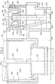
- the column preferably consisting of a motor vehicle steering column, is referenced 100 and illustrated in dashed dashed lines, while the assembly intended to be fixed on this column 100, and which preferably serves of support plate to at least one electrical switch under the steering wheel, is referenced 200.
- the fixing system according to the present invention shown in the appended figures for its part, essentially comprises a collar 300, a wedge 400 and a control screw 500.
- the steering column 100 can be the subject of numerous variants known in themselves. Column 100 will not be described in detail later.
- the column 100 can for example be stepped along its length.
- the assembly 200 can be the subject of numerous variant embodiments. Preferably, it is produced by plastic molding.
- the assembly 200 advantageously comprises a plate 210 serving as a support for at least one electric switch, for example for the control of the lighting means and light indicator means of the vehicle, as well as optionally the control of the wipers / windscreen wipers and windshield .
- the plate 210 can be adapted to carry other functions, for example a rotary contactor designed to provide an electrical connection between an element carried by the steering wheel, such as an airbag, rotatable, and control means fixed relative to the chassis.
- the plate 210 is formed of a plate which extends in a general direction perpendicular to the axis 102 of the column 100.
- the plate 210 carries a drum 220 axially split and therefore at least partially elastic, centered on the axis 102.
- the drum 220 thus at least partially surrounds the column 100.
- the barrel 220 comprises four sectors 221, 222, 223, 224.
- the main sector 221 is formed by a cylindrical cap having an angular opening of the order of 170 ° .
- This main sector 221 is substantially rigid.
- the other three sectors, secondary 222, 223, 224, elastic, evenly distributed opposite the main sector 221 each cover an angular opening of the order of 50 °, relative to the axis 102 of the column 100.
- the angular opening of the rigid main sector 221 is referenced ⁇ 1
- that of the elastic secondary sectors 222, 223, 224 is referenced ⁇ 2.
- the longitudinal slots formed between the different sectors, 221, 222, 223 and 224, to allow a radial deformation of these, are referenced 225, 226, 227 and 228.
- the support structure 230 provided on the assembly 200 to urge the wedge 400 and ensure the clamping of the collar 300 is formed radially on the outside of the main sector 221.
- this structure 230 comprises, at the level of the plate 210, a lower chamber 232 capable of at least partially receiving the corner 400.
- the chamber 232 can serve to position and originally maintain the corner 400.
- the chamber 232 has a straight section, orthogonal to the axis 102, generally rectangular, complementary to the corresponding section of the corner 400.
- the chamber 232 is provided in its base wall 233 with a through bore 234 which extends parallel to the axis 102 of the column.
- This hole 234 is designed to receive the rod 504 of the control screw 500.
- the dimensions of the hole 234 must be less than the section of the head 502 of the screw 500 so that the base wall 233 serves to support this head 502.
- the bore 234 is oblong and has its large dimension oriented radially with respect to the axis 102. This arrangement is provided to allow slight radial displacement. of the rod 102 under the effect of the radial displacement of the wedge 400, when the latter slides on a control ramp of the structure 230, as will be described later.
- the small dimension of the bore 234 must be complementary to the diameter of the rod 504 of the screw 500.
- the structure 230 comprises a face or ramp 235 serving as support and biasing at the corner 400 and two lateral walls 240, 242 which serve as a guide for the latter.
- the walls 240, 242 are mutually parallel and orthogonal to the bearing face 235.
- this bearing and stressing face 235 is generally flat and delimited by generatrices perpendicular to the axis 102 of the column and parallel to a cord connecting the ends of the main sector 221, which cord is referenced 219 in FIG. 1.
- bearing face 235 diverges with respect to the axis 102 in approach to the bottom of the chamber 232.
- the bearing face 235 defines a generally planar facet inclined with respect to the axis 102 by an angle ⁇ of the order of 10 to 15 °, advantageously of the order of 12 °.
- the bearing face 235 is formed on a rib 236 the apex 235 of which is formed of a plane facet inclined by the angle ⁇ relative to the axis 102 , which rib 236 is framed by two parallel grooves 237, 238.
- the grooves 237, 238 are thus adjacent respectively to the walls 240 and 242.
- the bottoms of the grooves 237, 238, referenced respectively 245, 246 are parallel to the top 235 of the rib 236.
- the internal faces 241, 243 of the walls 240, 242 are planar, mutually parallel and parallel to the axis 102, while being perpendicular to the aforementioned cord 219.
- the outer surface of the walls 240, 242 may in turn be substantially arbitrary.
- this outer surface of the walls 240, 242 comprises fabrics 250, 252 which connect the radially external ends 248, 249 of the walls 240, 242 and the main sector 221.
- the fabrics 250, 252 are tangentially connected to the sector principal 221.
- different walls 254 are preferably provided, parallel to each other and parallel to the axis 102, as well as orthogonal to the cord 219, for example five walls 254, between the main sector 221 and the wall forming the ramp 235
- These walls 254 as well as the fabrics 250, 252 ensure in combination the rigidity of the main sector 221.
- the different sectors 221, 222, 223, 224 of the split barrel 221 have, near their top and on their outer surface, teeth 229 designed to maintain the clamp 300.
- three teeth 229 are thus provided: a toothing 229 on sector 223, and two toothing 229 respectively on the external faces of fabrics 250 and 252.
- the collar 300 is advantageously made of metal.
- the collar 300 preferably comprises a generally cylindrical sector 310 two rectilinear bands 320, 322 and two returns 321, 323.
- the sector 310 has for example an angular opening of the order of 180 °. It is designed to cover, radially on the outside, the sectors 222, 223 and 224.
- the strips 320, 322 respectively extend the ends of the sector 310. They are flat and cover the exterior surfaces of the fabrics 250, 252. Thus, the bands 320, 322 converge, away from the axis 102.
- each band 320, 322 is provided at its end opposite to sector 310, with a return 321, 323.
- These two returns 321, 323 are adjacent, parallel to the axis 102 and to the cord 219. They cover the radially outer part of the structure 230.
- the two adjacent returns 321, 323 can be rigidly connected by any suitable means, for example using a welding point.
- This corner 400 is preferably made of metal.
- the first plane of symmetry referenced P passes through the axis 102.
- the second plane of symmetry referenced O orthogonal to the aforementioned plane of symmetry P, is parallel to the cord 219 and parallel to the axis 102.
- Corner 400 has the general shape of a parallelepipedal block. More specifically, the corner 400 is slightly tapered in the shape of a pyramid. It carries a tapped barrel 410 centered on an axis 412. The axis 412 corresponds to the intersection of the two planes of symmetry P and O. The axis 412 is parallel to the axis 102.
- the threaded barrel 410 is designed to receive the rod 504 of the control screw 500, as seen in FIG. 2.
- the wedge 400 is moved in translation substantially parallel to the axis 102 with a slight radial displacement relative to this axis 102, towards the outside, as will be explained below, during the screw 500 drive, to ensure the clamping of the collar 300 on the steering column 100.
- the corner 400 includes two main faces 420, 422, planar and parallel to each other.
- the distance separating the two main faces 420, 422 is substantially equal, while being slightly less, than the distance separating the internal surfaces 241, 243 from the walls 240, 242.
- the corner 400 is guided by the walls 240, 242 in translation substantially parallel to the axis 102.
- the corner 400 further comprises two secondary faces 430, 440 generally orthogonal to the main faces 420, 422. These faces 430, 440 respectively serve as support on the ramp 235 of the structure 230 integral with the assembly 200 on the one hand, and on the collar 300, more precisely on the internal surface of the return 323 on the other hand.
- these two faces 430, 440 are symmetrical with respect to the plane O, so that they can be reversed. Thanks to this symmetry, the assembly of the system is greatly facilitated, since it is not necessary to take the slightest precaution regarding the positioning of the corner 400 on the plate 200.
- each face 430, 440 comprises at least one facet 432, 442, preferably planar, inclined with respect to the axis 412.
- the facets 432, 442 converge with each other in approach to the base of the corner 400.
- the inclination between each facet 432, 442 and the axis 412 is preferably substantially equal to the inclination ⁇ of the ramp 235 relative to the axis 102.
- These facets 432, 442 are intended to rest on the ramp 235.
- each face 430, 440 of the corner 400 comprises two ribs 433, 443 which delimit support facets 434, 444 parallel to the axis 412. These facets 434, 444 serve as support for the collar 300.
- the ribs 433, 443 are respectively mutually parallel and adjacent to the main faces 420, 422.
- the ribs 433, 443 frame the support facets 432, 442.
- the facets 434, 444 parallel to the axis 412 are formed on the upper half-height of the ribs 433, 443, by the top of these, truncated for this purpose.
- the top of the ribs 433, 443, on the lower half-height of these is advantageously inclined relative to the axis 412, parallel to the support facets 432, 442.
- the height h projecting from the ribs 433, 443, relative to the bearing facets 432, 442 is less than the depth of the grooves 237, 238 provided on the structure 230.
- the corner 400 when the corner 400 is placed in the structure 230, and engaged on the screw 500, one of the facets 432, 442 rests on the ramp 235, the ribs 433 or 443 which frame this facet 432, 442 are placed in the grooves 237, 238, while the top 444 or 434 of the ribs 443 or 433 provided on the other secondary face rests on the interior surface of the return 323 linked to the clamp 300.
- the wedge 400 rests on the assembly 200 , via a facet inclined with respect to the axis 102, while the same corner 400 rests against the collar 300 via facets 444, 434 parallel to this axis 102.
- the corner 400 is immobilized in rotation on the structure 230, between the walls 240, 242.
- the screw 500 is engaged by the tapped barrel 410 with the corner 400.
- the screw 500 is itself immobilized in translation on the structure 230 since its head 502 rests against the base wall 233.
- the drive of the screw 500 causes the translational displacement of the wedge 400 in a general direction substantially parallel to the axis 102, in approach to the lower chamber 232.
- the wedge 400 slides on the ramp 235 inclined relative to the axis 102. Consequently, during this movement, the wedge 400 is displaced radially outward relative to the axis 102.
- the force exerted by the wedge 400 on the collar 300 is oriented radially, ie perpendicular to the axis 102.
- the tightening collar 300 is thus moved radially by relative to the axis 102. As a result, it operates on the elastic sectors 222, 223 and 224 a tightening force on the column 100 making it possible to fix the plate 200 on the latter.
- the arrangements in accordance with the present invention offer the advantage of avoiding any direct friction between the wedge 400 and the column 100, and therefore the invention makes it possible to avoid any risk of inadvertent blocking of the corner 400.
- the corner 400 is moreover preferably formed of a hollow body comprising a base wall 450 pierced opposite the threaded bore of the barrel 410 and which connects the walls 421, 423 , 431 and 441 forming the faces 420, 422, 430 and 440 mentioned above.
- the corner 400 preferably comprises, in its internal chamber 402 at least one fabric ensuring the connection between the external surface of the threaded barrel 410 and the internal surface of the aforementioned walls 421, 423, 431 and 441 of the corner.
- stiffening fabrics 460 are thus provided between the external surface of the barrel 410 and the internal surface of the walls 421, 423, 431, 441 delimiting the faces 420, 422, 430 and 440.
- system according to the present invention allows free angular adjustment of the plate 200 around the axis 102, on the column 100, before tightening the screw 500 and the collar 300.
- the biasing structure 230 it is necessary to adapt the biasing structure 230 accordingly, by replacing the rib central 235 framed by two grooves 237, 238, by a structure comprising a central groove similar to the grooves 237, 238, intended to receive the central rib provided on the corner, and framed by two symmetrical ribs s imilaries to the rib 236, delimiting a facet inclined with respect to the axis 102, to serve as support for the homologous facet of the corner 400.
Landscapes
- Engineering & Computer Science (AREA)
- Mechanical Engineering (AREA)
- Chemical & Material Sciences (AREA)
- Combustion & Propulsion (AREA)
- Transportation (AREA)
- General Engineering & Computer Science (AREA)
- Steering Controls (AREA)
- Connection Of Plates (AREA)
- Clamps And Clips (AREA)
Applications Claiming Priority (2)
| Application Number | Priority Date | Filing Date | Title |
|---|---|---|---|
| FR9411173 | 1994-09-20 | ||
| FR9411173A FR2724696B1 (fr) | 1994-09-20 | 1994-09-20 | Systeme de fixation d'un ensemble sur une colonne, notamment pour la fixation d'un ensemble de commutation electrique sur une colonne de direction de vehicule automobile |
Publications (2)
| Publication Number | Publication Date |
|---|---|
| EP0703371A1 true EP0703371A1 (de) | 1996-03-27 |
| EP0703371B1 EP0703371B1 (de) | 1998-11-11 |
Family
ID=9467075
Family Applications (1)
| Application Number | Title | Priority Date | Filing Date |
|---|---|---|---|
| EP95402102A Expired - Lifetime EP0703371B1 (de) | 1994-09-20 | 1995-09-19 | Vorrichtung zur Befestigung einer Anordnung an einer Säule, insbesondere für die Befestigung einer elektrischen Schaltvorrichtung an einer Kraftfahrzeuglenksäule |
Country Status (4)
| Country | Link |
|---|---|
| EP (1) | EP0703371B1 (de) |
| DE (1) | DE69505935T2 (de) |
| ES (1) | ES2125575T3 (de) |
| FR (1) | FR2724696B1 (de) |
Cited By (2)
| Publication number | Priority date | Publication date | Assignee | Title |
|---|---|---|---|---|
| FR2749354A1 (fr) * | 1996-05-30 | 1997-12-05 | Valeo Electronique | Support de commutateurs a collier de fixation pour vehicule automobile |
| EP1504964A1 (de) * | 2003-07-01 | 2005-02-09 | Valeo Schalter und Sensoren GmbH | Befestigungseinrichtung zur Befestigung eines Lenkstockmoduls an einem Lenkstock und Lenkstockmodul |
Citations (4)
| Publication number | Priority date | Publication date | Assignee | Title |
|---|---|---|---|---|
| US2679993A (en) * | 1951-07-18 | 1954-06-01 | Marman Products Company Inc | Axially tightening band clamp |
| EP0082997A1 (de) * | 1981-12-24 | 1983-07-06 | Nissan Motor Co., Ltd. | Festlegungseinrichtung eines Schalters am Lenkrohr |
| EP0152311A2 (de) * | 1984-01-20 | 1985-08-21 | Regie Nationale Des Usines Renault | Vorrichtung zur Befestigung und winklichen Einstellung einer Kunststoffplatte an einem zylindrischen Gegenstand |
| FR2699468A1 (fr) * | 1992-12-18 | 1994-06-24 | Renault | Dispositif de réglage angulaire d'un module de commande d'équipements électriques de véhicule automobile. |
-
1994
- 1994-09-20 FR FR9411173A patent/FR2724696B1/fr not_active Expired - Fee Related
-
1995
- 1995-09-19 ES ES95402102T patent/ES2125575T3/es not_active Expired - Lifetime
- 1995-09-19 DE DE69505935T patent/DE69505935T2/de not_active Expired - Fee Related
- 1995-09-19 EP EP95402102A patent/EP0703371B1/de not_active Expired - Lifetime
Patent Citations (4)
| Publication number | Priority date | Publication date | Assignee | Title |
|---|---|---|---|---|
| US2679993A (en) * | 1951-07-18 | 1954-06-01 | Marman Products Company Inc | Axially tightening band clamp |
| EP0082997A1 (de) * | 1981-12-24 | 1983-07-06 | Nissan Motor Co., Ltd. | Festlegungseinrichtung eines Schalters am Lenkrohr |
| EP0152311A2 (de) * | 1984-01-20 | 1985-08-21 | Regie Nationale Des Usines Renault | Vorrichtung zur Befestigung und winklichen Einstellung einer Kunststoffplatte an einem zylindrischen Gegenstand |
| FR2699468A1 (fr) * | 1992-12-18 | 1994-06-24 | Renault | Dispositif de réglage angulaire d'un module de commande d'équipements électriques de véhicule automobile. |
Cited By (2)
| Publication number | Priority date | Publication date | Assignee | Title |
|---|---|---|---|---|
| FR2749354A1 (fr) * | 1996-05-30 | 1997-12-05 | Valeo Electronique | Support de commutateurs a collier de fixation pour vehicule automobile |
| EP1504964A1 (de) * | 2003-07-01 | 2005-02-09 | Valeo Schalter und Sensoren GmbH | Befestigungseinrichtung zur Befestigung eines Lenkstockmoduls an einem Lenkstock und Lenkstockmodul |
Also Published As
| Publication number | Publication date |
|---|---|
| FR2724696A1 (fr) | 1996-03-22 |
| EP0703371B1 (de) | 1998-11-11 |
| DE69505935D1 (de) | 1998-12-17 |
| DE69505935T2 (de) | 1999-08-05 |
| FR2724696B1 (fr) | 1997-01-24 |
| ES2125575T3 (es) | 1999-03-01 |
Similar Documents
| Publication | Publication Date | Title |
|---|---|---|
| EP1544035B1 (de) | Vorderer Karosserieaufbau eines Kraftfahrzeuges mit verbesserten Befestigungs- und Lagejustiermitteln, und Kraftfahrzeug ausgestattet mit einem solchen Aufbau | |
| FR2808483A1 (fr) | Dispositif de reglage motorise pour siege de vehicule | |
| EP0239440A1 (de) | Einstellungseinrichtung, zum Beispeil für Fahrzeugleuchte | |
| FR2576245A1 (fr) | Procede d'enrobage d'un capteur allonge, dispositif de moulage pour la mise en oeuvre du procede, capteur obtenu et armature intervenant dans la fabrication du capteur | |
| FR2800810A1 (fr) | Dispositif de fixation, notamment pour la fixation d'une piece d'habillage, telle qu'une aile en matiere plastique contre un support tel qu'une piece de carrosserie | |
| FR2578594A1 (fr) | Noix d'assujettissement d'une plaque a un tube | |
| EP0703371B1 (de) | Vorrichtung zur Befestigung einer Anordnung an einer Säule, insbesondere für die Befestigung einer elektrischen Schaltvorrichtung an einer Kraftfahrzeuglenksäule | |
| WO2012110274A1 (fr) | Dispositif de commande ou de signalisation electrique | |
| FR2580696A1 (fr) | Support de pilier et verin cooperant avec un tel support et avec un plancher technique | |
| EP3115623B1 (de) | Vorrichtung zum zusammenbau und zur verriegelung | |
| FR2925418A1 (fr) | Boitier de feu de signalisation d'un vehicule automobile avec fixation centrale par le connecteur du porte-lampe | |
| FR2632588A1 (fr) | Dispositif de montage reglable d'un appui-tete | |
| FR2687741A1 (fr) | Dispositif de fixation d'une piece sur un profile menageant une rainure de retenue. | |
| FR2713170A1 (fr) | Porte-plaque minéralogique pour véhicule automobile. | |
| FR2772441A1 (fr) | Dispositif de fixation concu pour le maintien d'une piece | |
| FR2504872A1 (fr) | Support de retroviseur et procede pour sa fabrication | |
| EP1186837B1 (de) | Vorrichtung zur Wandbefestigung eines Heizkörpers und Verfahren zu dessen Befestigung | |
| EP1108950B1 (de) | Kraftfahrzeugscheinwerfer mit verbesserten Lampenverriegelungsmitteln | |
| EP1800949B1 (de) | Signalleuchteneinheit für ein Kraftfahrzeug mit einer Stange, welche mit einem Positionierungsteil und einem Teil zur Befestigung an der Karosserie versehen ist. | |
| FR2710882A1 (fr) | Ensemble de fixation d'une platine sur une colonne, notamment pour la fixation d'une platine de commutateur électrique sur une colonne de direction de véhicule automobile. | |
| FR2486173A1 (fr) | Dispositif de fixation pour appareils a encastrer | |
| FR2594761A1 (fr) | Dispositif de fixation reglable, notamment pour projecteur de vehicule automobile | |
| FR2822440A1 (fr) | Reservoir pour circuit de liquide dans un vehicule automobile et procede de fabrication d'un tel reservoir | |
| FR3132253A1 (fr) | Panneau de véhicule automobile intégrant un élément lumineux | |
| FR2769886A1 (fr) | Dispositif de fermeture perfectionne pour tableau de bord de vehicule automobile |
Legal Events
| Date | Code | Title | Description |
|---|---|---|---|
| PUAI | Public reference made under article 153(3) epc to a published international application that has entered the european phase |
Free format text: ORIGINAL CODE: 0009012 |
|
| AK | Designated contracting states |
Kind code of ref document: A1 Designated state(s): DE ES GB IT |
|
| 17P | Request for examination filed |
Effective date: 19960924 |
|
| GRAG | Despatch of communication of intention to grant |
Free format text: ORIGINAL CODE: EPIDOS AGRA |
|
| 17Q | First examination report despatched |
Effective date: 19980113 |
|
| GRAG | Despatch of communication of intention to grant |
Free format text: ORIGINAL CODE: EPIDOS AGRA |
|
| GRAH | Despatch of communication of intention to grant a patent |
Free format text: ORIGINAL CODE: EPIDOS IGRA |
|
| GRAH | Despatch of communication of intention to grant a patent |
Free format text: ORIGINAL CODE: EPIDOS IGRA |
|
| GRAA | (expected) grant |
Free format text: ORIGINAL CODE: 0009210 |
|
| AK | Designated contracting states |
Kind code of ref document: B1 Designated state(s): DE ES GB IT |
|
| REF | Corresponds to: |
Ref document number: 69505935 Country of ref document: DE Date of ref document: 19981217 |
|
| GBT | Gb: translation of ep patent filed (gb section 77(6)(a)/1977) |
Effective date: 19990114 |
|
| REG | Reference to a national code |
Ref country code: ES Ref legal event code: FG2A Ref document number: 2125575 Country of ref document: ES Kind code of ref document: T3 |
|
| PLBE | No opposition filed within time limit |
Free format text: ORIGINAL CODE: 0009261 |
|
| STAA | Information on the status of an ep patent application or granted ep patent |
Free format text: STATUS: NO OPPOSITION FILED WITHIN TIME LIMIT |
|
| PG25 | Lapsed in a contracting state [announced via postgrant information from national office to epo] |
Ref country code: GB Free format text: LAPSE BECAUSE OF NON-PAYMENT OF DUE FEES Effective date: 19990919 |
|
| 26N | No opposition filed | ||
| GBPC | Gb: european patent ceased through non-payment of renewal fee |
Effective date: 19990919 |
|
| PG25 | Lapsed in a contracting state [announced via postgrant information from national office to epo] |
Ref country code: DE Free format text: LAPSE BECAUSE OF NON-PAYMENT OF DUE FEES Effective date: 20000701 |
|
| PGFP | Annual fee paid to national office [announced via postgrant information from national office to epo] |
Ref country code: ES Payment date: 20030923 Year of fee payment: 9 |
|
| PG25 | Lapsed in a contracting state [announced via postgrant information from national office to epo] |
Ref country code: ES Free format text: LAPSE BECAUSE OF NON-PAYMENT OF DUE FEES Effective date: 20040920 |
|
| PG25 | Lapsed in a contracting state [announced via postgrant information from national office to epo] |
Ref country code: IT Free format text: LAPSE BECAUSE OF NON-PAYMENT OF DUE FEES;WARNING: LAPSES OF ITALIAN PATENTS WITH EFFECTIVE DATE BEFORE 2007 MAY HAVE OCCURRED AT ANY TIME BEFORE 2007. THE CORRECT EFFECTIVE DATE MAY BE DIFFERENT FROM THE ONE RECORDED. Effective date: 20050919 |
|
| REG | Reference to a national code |
Ref country code: ES Ref legal event code: FD2A Effective date: 20040920 |