EP0703377B1 - Drehmomentübertragungseinrichtung und seine Steuerung - Google Patents
Drehmomentübertragungseinrichtung und seine Steuerung Download PDFInfo
- Publication number
- EP0703377B1 EP0703377B1 EP95202032A EP95202032A EP0703377B1 EP 0703377 B1 EP0703377 B1 EP 0703377B1 EP 95202032 A EP95202032 A EP 95202032A EP 95202032 A EP95202032 A EP 95202032A EP 0703377 B1 EP0703377 B1 EP 0703377B1
- Authority
- EP
- European Patent Office
- Prior art keywords
- pressure
- torque transmitting
- valve means
- control
- passage
- Prior art date
- Legal status (The legal status is an assumption and is not a legal conclusion. Google has not performed a legal analysis and makes no representation as to the accuracy of the status listed.)
- Expired - Lifetime
Links
- 239000012530 fluid Substances 0.000 claims description 45
- 238000004891 communication Methods 0.000 claims description 7
- 230000005540 biological transmission Effects 0.000 description 29
- 230000008859 change Effects 0.000 description 3
- 230000001276 controlling effect Effects 0.000 description 3
- 230000007246 mechanism Effects 0.000 description 3
- 238000006243 chemical reaction Methods 0.000 description 2
- 230000000712 assembly Effects 0.000 description 1
- 238000000429 assembly Methods 0.000 description 1
- 230000008901 benefit Effects 0.000 description 1
- 230000001143 conditioned effect Effects 0.000 description 1
- 238000006073 displacement reaction Methods 0.000 description 1
- 230000000977 initiatory effect Effects 0.000 description 1
- 238000000034 method Methods 0.000 description 1
- 230000007935 neutral effect Effects 0.000 description 1
- JTJMJGYZQZDUJJ-UHFFFAOYSA-N phencyclidine Chemical compound C1CCCCN1C1(C=2C=CC=CC=2)CCCCC1 JTJMJGYZQZDUJJ-UHFFFAOYSA-N 0.000 description 1
- 238000002360 preparation method Methods 0.000 description 1
- 230000008569 process Effects 0.000 description 1
- 230000008929 regeneration Effects 0.000 description 1
- 238000011069 regeneration method Methods 0.000 description 1
- 230000001105 regulatory effect Effects 0.000 description 1
- 230000004044 response Effects 0.000 description 1
Images


Classifications
-
- F—MECHANICAL ENGINEERING; LIGHTING; HEATING; WEAPONS; BLASTING
- F16—ENGINEERING ELEMENTS AND UNITS; GENERAL MEASURES FOR PRODUCING AND MAINTAINING EFFECTIVE FUNCTIONING OF MACHINES OR INSTALLATIONS; THERMAL INSULATION IN GENERAL
- F16D—COUPLINGS FOR TRANSMITTING ROTATION; CLUTCHES; BRAKES
- F16D43/00—Automatic clutches
- F16D43/28—Automatic clutches actuated by fluid pressure
-
- F—MECHANICAL ENGINEERING; LIGHTING; HEATING; WEAPONS; BLASTING
- F16—ENGINEERING ELEMENTS AND UNITS; GENERAL MEASURES FOR PRODUCING AND MAINTAINING EFFECTIVE FUNCTIONING OF MACHINES OR INSTALLATIONS; THERMAL INSULATION IN GENERAL
- F16D—COUPLINGS FOR TRANSMITTING ROTATION; CLUTCHES; BRAKES
- F16D25/00—Fluid-actuated clutches
- F16D25/12—Details not specific to one of the before-mentioned types
- F16D25/14—Fluid pressure control
-
- F—MECHANICAL ENGINEERING; LIGHTING; HEATING; WEAPONS; BLASTING
- F16—ENGINEERING ELEMENTS AND UNITS; GENERAL MEASURES FOR PRODUCING AND MAINTAINING EFFECTIVE FUNCTIONING OF MACHINES OR INSTALLATIONS; THERMAL INSULATION IN GENERAL
- F16D—COUPLINGS FOR TRANSMITTING ROTATION; CLUTCHES; BRAKES
- F16D48/00—External control of clutches
- F16D48/02—Control by fluid pressure
- F16D48/04—Control by fluid pressure providing power assistance
-
- F—MECHANICAL ENGINEERING; LIGHTING; HEATING; WEAPONS; BLASTING
- F16—ENGINEERING ELEMENTS AND UNITS; GENERAL MEASURES FOR PRODUCING AND MAINTAINING EFFECTIVE FUNCTIONING OF MACHINES OR INSTALLATIONS; THERMAL INSULATION IN GENERAL
- F16H—GEARING
- F16H63/00—Control outputs from the control unit to change-speed- or reversing-gearings for conveying rotary motion or to other devices than the final output mechanism
- F16H63/02—Final output mechanisms therefor; Actuating means for the final output mechanisms
- F16H63/30—Constructional features of the final output mechanisms
- F16H63/3023—Constructional features of the final output mechanisms the final output mechanisms comprising elements moved by fluid pressure
- F16H63/3026—Constructional features of the final output mechanisms the final output mechanisms comprising elements moved by fluid pressure comprising friction clutches or brakes
-
- F—MECHANICAL ENGINEERING; LIGHTING; HEATING; WEAPONS; BLASTING
- F16—ENGINEERING ELEMENTS AND UNITS; GENERAL MEASURES FOR PRODUCING AND MAINTAINING EFFECTIVE FUNCTIONING OF MACHINES OR INSTALLATIONS; THERMAL INSULATION IN GENERAL
- F16D—COUPLINGS FOR TRANSMITTING ROTATION; CLUTCHES; BRAKES
- F16D48/00—External control of clutches
- F16D48/02—Control by fluid pressure
- F16D2048/0221—Valves for clutch control systems; Details thereof
-
- F—MECHANICAL ENGINEERING; LIGHTING; HEATING; WEAPONS; BLASTING
- F16—ENGINEERING ELEMENTS AND UNITS; GENERAL MEASURES FOR PRODUCING AND MAINTAINING EFFECTIVE FUNCTIONING OF MACHINES OR INSTALLATIONS; THERMAL INSULATION IN GENERAL
- F16D—COUPLINGS FOR TRANSMITTING ROTATION; CLUTCHES; BRAKES
- F16D48/00—External control of clutches
- F16D48/02—Control by fluid pressure
- F16D2048/0224—Details of conduits, connectors or the adaptors therefor specially adapted for clutch control
-
- F—MECHANICAL ENGINEERING; LIGHTING; HEATING; WEAPONS; BLASTING
- F16—ENGINEERING ELEMENTS AND UNITS; GENERAL MEASURES FOR PRODUCING AND MAINTAINING EFFECTIVE FUNCTIONING OF MACHINES OR INSTALLATIONS; THERMAL INSULATION IN GENERAL
- F16D—COUPLINGS FOR TRANSMITTING ROTATION; CLUTCHES; BRAKES
- F16D48/00—External control of clutches
- F16D48/02—Control by fluid pressure
- F16D2048/0257—Hydraulic circuit layouts, i.e. details of hydraulic circuit elements or the arrangement thereof
- F16D2048/0263—Passive valves between pressure source and actuating cylinder, e.g. check valves or throttle valves
-
- F—MECHANICAL ENGINEERING; LIGHTING; HEATING; WEAPONS; BLASTING
- F16—ENGINEERING ELEMENTS AND UNITS; GENERAL MEASURES FOR PRODUCING AND MAINTAINING EFFECTIVE FUNCTIONING OF MACHINES OR INSTALLATIONS; THERMAL INSULATION IN GENERAL
- F16D—COUPLINGS FOR TRANSMITTING ROTATION; CLUTCHES; BRAKES
- F16D48/00—External control of clutches
- F16D48/02—Control by fluid pressure
- F16D2048/0257—Hydraulic circuit layouts, i.e. details of hydraulic circuit elements or the arrangement thereof
- F16D2048/0266—Actively controlled valves between pressure source and actuation cylinder
-
- F—MECHANICAL ENGINEERING; LIGHTING; HEATING; WEAPONS; BLASTING
- F16—ENGINEERING ELEMENTS AND UNITS; GENERAL MEASURES FOR PRODUCING AND MAINTAINING EFFECTIVE FUNCTIONING OF MACHINES OR INSTALLATIONS; THERMAL INSULATION IN GENERAL
- F16D—COUPLINGS FOR TRANSMITTING ROTATION; CLUTCHES; BRAKES
- F16D48/00—External control of clutches
- F16D48/02—Control by fluid pressure
- F16D2048/0257—Hydraulic circuit layouts, i.e. details of hydraulic circuit elements or the arrangement thereof
- F16D2048/0281—Complex circuits with more than two valves in series or special arrangements thereof not provided for in previous groups
Definitions
- This invention relates to a fluid actuated friction torque transmitting device and control for friction devices in multi-speed power transmissions, and more particularly, for shift controls providing pressure for a controlled torque capacity at a clutch during torque reversal.
- Automatic transmissions utilize one or more mechanically actuated one-way clutches, such as sprags or roller clutches, to eliminate potential interference during a shift interchange.
- the one-way clutches function similar to a very stiff spring in the forward direction and provide a step change in the effective spring rate which changes abruptly to a zero spring rate with a small amount of drag torque when the direction of torque transmission is reversed. These one-way clutches do not exhibit any perceptible delay in the apply or release conditions.
- Hydraulic one-way clutches have been proposed for a number of years. There are a variety of ways of executing a hydraulic one-way clutch, but the most common is to use rotational lash valves to switch piston apply pressure on or off, depending upon the relative direction of torque. These devices have an advantage over the mechanical one-way clutch in that the apply pressure can be modulated to dissipate energy on apply or release and can provide two-way torque transmission when desired.
- the prior art transmissions utilizing one-way clutches frequently place a conventional friction device in series with the one-way device to provide for engine braking during coast operation.
- the present invention proposes a fluid actuated friction torque transmitting device and control which will permit the friction device to simulate a one-way clutch operation.
- a fluid actuated friction torque transmitting device and control in accordance with the present invention is characterised over US-A-4,969,546 by the features specified in the characterising portion of Claim 1.
- the hydraulic control unit is effective to feed a tickle or light pressure through a series of check balls just prior to initiating a downshift. This pressure will minimize the apply delay by keeping the clutch piston stroked and ready to receive the higher pressure when the torque reverses. With the control ability to turn the tickle pressure off, it will still provide a one-way clutch that has no torque capacity beyond the drag of an opened friction clutch.
- a pressure control regulator valve establishes a low pressure fluid source to control the piston stroke of a torque transmitting friction device when the friction device is in the normally de-energized position.
- control valves are operable to provide the highest system pressure available to the operating piston of the friction device.
- a further aspect of this invention is seen in a control for a fluid operated torque transmitting friction device, in which a low regulating pressure or exhaust pressure is controlled by a solenoid valve.
- a still further aspect of this invention utilizes a control and torque transmitting friction device which is effective to replace two one-way clutches and two hydraulic clutches with a single hydraulic fluid operated friction device.
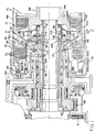
- Figure 1 is a cross-sectional elevational view of a portion of a multi-speed power transmission utilizing the present invention.
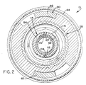
- Figure 2 is a view taken along line 2--2 of Figure 1.
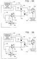
- Figures 3A, 3B, 3C, 3D, 3E, 3F and 3G are schematic representations of a control for operating one of the friction devices shown in Figure 1 during various operating conditions of the transmission.
- FIG. 4 is a schematic representation of an alternative embodiment of the control mechanism for the present invention.
- Figure 1 depicts a portion of a power transmission 10 which includes two fluid operated clutch assemblies 12 and 14 and a fluid operated disc brake assembly 16 and a band brake assembly 18.
- the disc brake assembly 16 is disposed parallel with a one-way brake, such that coast control of the transmission can be achieved.
- the clutch assembly 12 includes an input hub 28 which has a splined outer surface 30 to which is splined a plurality of friction plates 32. Alternating with the friction plates 32 is a plurality of friction plates 34 which are splined to a clutch housing 36.
- a hydraulic piston 38 is slidably disposed in the housing 36 and is operable in response to fluid pressure in a chamber 40 to enforce frictional engagement between the plates 32 and 34.
- the housing 36 is connected at a spline interface 42 to a transfer sleeve 44 which in turn is connected to one or more members of a planetary gear arrangement, not shown, which may be constructed in accordance with those described in U.S. Patent Nos. 5,069,656, issued to Sherman on December 3, 1991; 4,237,749 issued to Koivunen on December 9, 1980; 4,086,827 issued to Chana on May 2, 1978; 2,856,794 issued to Simpson on October 21, 1958; or any other well known arrangements.
- the clutch assembly 14 includes an input clutch housing 80 which is drivingly connected through tangs 82 to the input hub 28 and therefore to an input shaft 84.
- the input shaft 84 receives power from a conventional torque converter, not shown, through an input chain 86 and an input sprocket 88. This is a conventional input system for a power transmission.
- the clutch assembly 14 also includes an output hub 89 and a plurality of interleaved friction plates 90 and 92 splined to the hub 89 and housing 80, respectively.
- the hub 89 is integrally formed or otherwise secured with sun gear 54, which is a component of the planetary arrangement. Whenever the clutch assembly 14 is fully engaged, the gear 54 will rotate at the speed of the input shaft.
- the hub 89 is connected with the brake 16 by a sleeve shaft 91, such that the gear 54 may be held stationary by brake 16.
- the clutch assembly 14 further includes a hydraulically operated piston 96 which is controlled to selectively engage and disengage the clutch assembly 14 by fluid pressure in a chamber 98.
- the piston 96 cooperates with an annular wall 100 to form a control chamber 102 which is in continuous fluid communication with a lube passage 104. Fluid pressure in the lube passage 104 will assist a plurality of return springs 106 to disengage the clutch and prevent clutch drifting on engagement due to centrifugal pressures.
- the chamber 98 has a first supply passage or port 107 and a second supply passage or port 108 which are in fluid communication with control passages 110 and 112, respectively.
- the fluid pressure available to the chamber 98 from the passages 110 and 112 is controlled by a sleeve valve 114 which is operable to rotate with the clutch housing 80.
- the drive tangs 82 are operable to permit relative angular excursion between the clutch housing 80 and the input hub 28.
- the sleeve valve 114 is rotated relative to the input shaft 84 so as to control the source of fluid pressure for the chamber 98.
- the passage 110 is in fluid communication through passage 107 with the chamber 98, such that whatever fluid pressure is available in passage 110 would be available to energize the piston 96. If the clutch housing is rotated counterclockwise relative to the hub 28, the sleeve valve 114 will align to provide fluid communication between passage 108 and the chamber 98. Thus, in the adjusted position, the fluid pressure available in passage 112 is available to control the energization of the piston 96.
- the passages 110 and 112 are lunate in cross section and have the outer surface thereof controlled by the input shaft 84 and the inner edge controlled by a sleeve seal 116. Thus, the two pressures or passages 110 and 112 will not intermix.
- the pressure in passage 110 will be controlling and when a reverse or negative torque is placed on the clutch assembly 14, the fluid pressure in passage 112 will be controlling.
- the clutch 14 and associated valving structure will provide for the replacement of two fluid operated clutches and two one-way clutches in at least one commercially available transmission.
- a hydraulic pressure supply and control mechanism 120 which is a conventional device in automatic power transmissions.
- the control 120 will generally include a positive displacement high pressure pump, control valves for determining when shift interchanges or ratio interchanges are to be accomplished, electronic devices for controlling pressures within the system and a CPU or processing unit which takes the form of a programmed digital computer to establish the operating sequences of the transmission. These devices are well known and it is believed that those skilled in the art will not need further description at this point.
- the sleeve valve 114A is disposed in fluid communication with a friction device 14A, such that fluid pressure from passages 110 and 112 is controlled for distribution to enforce the engagement control of the friction device of 14A.
- the hydraulic control 120 supplies pressure through a passage 122 to a ball check or shuttle valve 126 and through a passage 128 to a ball check or shuttle valve 130.
- the pressure in passages 122 and 128 is determined in accordance with the desired operating sequence of the transmission by the control 120.
- the pressure in passage 122 and 128 can be either high pressure or low pressure depending upon the condition to be established within the transmission.
- the hydraulic control 120 also supplies line pressure, which is the highest pressure in the system, to a passage 132 from which it is distributed to a control valve 134 and a solenoid valve 136.
- the solenoid valve 136 is a conventional-on/off solenoid and the control valve 134 is a conventional downstream pressure regulator valve.
- Such valves 134 are known to be used to control the pressure downstream of the valve independently of the incoming or line pressure in this instance.
- the downstream passage 138 of the control valve 134 is in fluid communication with both ball check valves 126 and 130.
- the control valve 134 also has a control pressure from a passage 140 which is established by the solenoid valve 136.
- the pressure in passage 140 is supplied through a restriction or orifice 142 from the line pressure in passage 132.
- the solenoid valve 136 is off, as shown in Figure 3A, the passage 140 is exhausted through the solenoid valve 136 and therefore the control pressure at valve 134 is zero resulting in substantially zero pressure in passage 138.
- the solenoid valve 136 is energized, such that the passage 140 is blocked from exhaust and a high pressure fluid in passage 132 will be directed to the control valve 134 resulting in a controlled pressure being available in passage 138.
- the pressure in passage 138 will be denoted as a tickle pressure.
- the tickle pressure in passage 138 is designed to be sufficient to fill the chamber 98 of clutch assembly 14 with sufficient pressure, such that the piston 96 will be brought into pre-engagement with the friction plates 90 and 92. In this condition, the return springs 106 will be slightly compressed and the friction plates 90 and 92 will be positioned to begin frictional torque transmission.
- the fluid pressure in passages 122 and 128 in Figure 3A is at an elevated level.
- the level of pressure is sufficient to provide full engagement of the clutch assembly 14.
- the clutch 14 is engaged independent of the direction of torque transmission. This is the condition which the pressure control 120 whenever the operator has selected manual first or manual third operation. During either of these operations, the operator has requested that engine braking be available, thus the clutch assembly 14 is to be engaged whether there is a positive engine transmitting torque or a negative vehicle transmitting torque being imposed thereon.
- the schematic shown in Figure 3C is the condition during second gear forward operation and during a 1-2 upshift. During this condition, the passage 122 is pressurized with high-pressure while the remaining control passages are exhausted.
- FIG. 3D The schematic representation of Figure 3D describes a 2-1 interchange or downshift.
- the fluid pressure in passage 122 is high pressure
- the fluid pressure in passage 128 is exhaust or low pressure
- the fluid pressure in passage 138 is the tickle pressure.
- the tickle pressure positions the piston 96 to the pre-engagement position described above, and establishes a slight drag torque in the system.
- the schematic representation in Figure 3E is that which is achieved during third gear or during a 2-3 upshift or 3-2 downshift.
- the passage 122 and 138 are both exhaust pressure and the passage 128 is high pressure.
- the chamber 98 is fed fluid pressure via passage 112 and that passage is high pressure.
- the planetary gear arrangement is such that the sun gear 54 is attempting to transmit torque back to the engine or is undergoing a regeneration process. Because of the direction of torque, the valve 114 will assume the position shown in Figure 3E, such that fluid pressure in passage 112 enforces engagement of the clutch 14. With both clutch 14 and clutch 12 engaged, the transmission is conditioned for third gear operation.
- the schematic representation in Figure 3F is the fourth gear operation or the 3-4 upshift operation.
- the pressures in passages 122, 128 and 138 are the same as for the third gear portion of Figure 3E.
- the brake 16 is engaged which causes the sun gear 54 to have a forward reaction.
- This causes the valve 114 to assume the position shown in Figure 3F which connects the chamber 98 to the passage 110.
- the passage 110 is connected through the shuttle valve 126 through passages 122 and 138, both of which are controlled at the exhaust level and therefore the clutch 14 is disengaged.
- the schematic representation shown in Figure 4 is a control mechanism which permits direct pressure control at the clutch 14.
- the passages 110 and 112 are pressurized by pulse width modulated (PWM) solenoid valves 144 and 146, respectively.
- PWM pulse width modulated
- the pressure output of these valves can be controlled between exhaust level and line pressure by the duty cycle imposed on the solenoid.
- This duty cycle is provided by the CPU which is available in the control 120.
- the pressure in passages 110 and 112 can be controlled at the desired levels to provide the same functions as described above for Figures 3A through 3G. That is, the clutch assembly 14 can be controlled to transmit full torque in both directions of operation as with Figure 3A, to provide one-way operation with a tickle torque as described in Figures 3D and 3G.
- the PWM solenoid 146 maintains a tickle pressure in passage 112 and the solenoid 144 maintains high pressure in passage 110.
- the pulse width modulated solenoid 144 establishes a tickle pressure in passage 110, and the PWM solenoid 146 establishes full pressure in passage 112.
- control system and friction device are operable to provide a hydraulic one-way clutch which is capable of operating in either direction of torque transmission as a one-way torque transmitter, while the opposite direction provides full torque transmission and is capable of being fully exhausted whenever it is desired to transmit no torque through the clutch.
Landscapes
- Engineering & Computer Science (AREA)
- General Engineering & Computer Science (AREA)
- Physics & Mathematics (AREA)
- Fluid Mechanics (AREA)
- Mechanical Engineering (AREA)
- Control Of Transmission Device (AREA)
Claims (4)
- Fluidbetätigte Reibungsdrehmomentübertragungsvorrichtung und Steuerung mit:dadurch gekennzeichnet, daß die Steuerung aufweisteinem Wellenmittel (84, 88);einem das Wellenmittel enthaltenden Mittel (89) zum Übertragen eines Drehmoments vom fluidbetätigten Reibungsdrehmomentübertragungsmittel (14) zu einem Fahrzeug und vom Fahrzeug zum fluidbetätigten Reibungsdrehmomentübertragungsmittel;einem Stromsteuerventilmittel (114), das für eine Drehung mit dem Wellenmittel (84, 88) angeordnet ist und ein Totgangmittel (82) enthält, um eine begrenzte relative Bewegung zwischen dem Wellenmittel und dem Stromsteuerventilmittel (114) zu gestatten;ein erstes Steuerventilmittel (126) zum selektiven Leiten eines gesteuerten Drucks zum Stromsteuerventilmittel (114), wenn das Drehmomentübertragungsmittel (89) ein Drehmoment vom fluidbetätigten Reibungsdrehmomentübertragungsmittel (14) überträgt,ein zweites Steuerventilmittel (130) zum selektiven Leiten eines gesteuerten Drucks zum Stromsteuerventilmittel (114), wenn das Drehmomentübertragungsmittel (89) ein Drehmoment zum fluidbetätigten Reibungsdrehmomentübertragungsmittel (14) überträgt.
- Fluidbetätigte Reibungsdrehmomentübertragungsvorrichtung und Steuerung nach Anspruch 1, ferner miteinem fluidbetätigten Kolbenmittel (96) zum Einrücken des fluidbetätigten Reibungsdrehmomentübertragungsmittels (14);worin das Stromsteuerventilmittel ein richtungsabhängiges Stromsteuerventilmittel (114) mit zwei Eingangsöffnungen (107, 108) ist, wobei das Totgangmittel (82) eine Fluidverbindung zwischen den Eingangsöffnungen und dem fluidbetätigten Kolbenmittel selektiv steuert;und worin die ersten und zweiten Steuerventilmittel Wechselventilmittel (126, 130) sind.
- Fluidbetätigte Reibungsdrehmomentübertragungsvorrichtung und Steuerung nach Anspruch 2, worin jedes Wechselventilmittel (126, 130) wirksam ist, um einen höheren von zwei, darauf beaufschlagten Drücken an jeweilige Eingangsöffnungen (107, 108) des richtungsabhängigen Stromsteuerventilmittels (114) zu verteilen.
- Fluidbetätigte Reibungsdrehmomentübertragungsvorrichtung und Steuerung nach Anspruch 3, worin ein Drucksteuerventilmittel (134) wirksam ist, um einen Steuerdruck selektiv an die beiden Wechselventilmittel (126, 130) zu verteilen.
Applications Claiming Priority (2)
| Application Number | Priority Date | Filing Date | Title |
|---|---|---|---|
| US294168 | 1989-01-05 | ||
| US08/294,168 US5535865A (en) | 1994-08-22 | 1994-08-22 | Torque transmitting friction device and control |
Publications (2)
| Publication Number | Publication Date |
|---|---|
| EP0703377A1 EP0703377A1 (de) | 1996-03-27 |
| EP0703377B1 true EP0703377B1 (de) | 1998-10-28 |
Family
ID=23132204
Family Applications (1)
| Application Number | Title | Priority Date | Filing Date |
|---|---|---|---|
| EP95202032A Expired - Lifetime EP0703377B1 (de) | 1994-08-22 | 1995-07-24 | Drehmomentübertragungseinrichtung und seine Steuerung |
Country Status (3)
| Country | Link |
|---|---|
| US (1) | US5535865A (de) |
| EP (1) | EP0703377B1 (de) |
| DE (1) | DE69505621T2 (de) |
Families Citing this family (8)
| Publication number | Priority date | Publication date | Assignee | Title |
|---|---|---|---|---|
| ES2128920B1 (es) * | 1996-02-02 | 1999-12-16 | Coop Goizper S | Sistema hidraulico para el control de frenos, embragues y frenos-embragues. |
| US5720374A (en) * | 1996-08-13 | 1998-02-24 | General Motors Corporation | Backfill pressure control valve for a rotating clutch |
| DE10158894A1 (de) * | 2001-11-30 | 2003-06-12 | Zahnradfabrik Friedrichshafen | Automatgetriebe |
| DE10207076A1 (de) * | 2002-02-20 | 2003-08-28 | Zahnradfabrik Friedrichshafen | Ölversorgungseinrichtung |
| WO2010033780A1 (en) * | 2008-09-18 | 2010-03-25 | Luxim Corporation | Electrodeless plasma lamp and drive circuit |
| US8256600B2 (en) * | 2009-08-07 | 2012-09-04 | GM Global Technology Operations LLC | Torque-transmitting mechanism having a compact piston and spring assembly |
| DE102010062665A1 (de) * | 2010-12-08 | 2012-06-14 | Zf Friedrichshafen Ag | Vorrichtung zum Koppeln wenigstens eines drehbar ausgeführten Bauteils mit einem gehäusefest ausgebildeten Bauteil einer Getriebeeinrichtung |
| DE102016215214A1 (de) * | 2016-08-16 | 2018-02-22 | Zf Friedrichshafen Ag | Getriebevorrichtung mit mehreren über hydraulisch betätigbare Kolben-Zylinder-Einrichtungen verstellbare Schaltstangen ein- und auslegbaren Übersetzungen |
Family Cites Families (12)
| Publication number | Priority date | Publication date | Assignee | Title |
|---|---|---|---|---|
| US2856794A (en) | 1955-12-13 | 1958-10-21 | Howard W Simpson | Planetary transmission for self-propelled vehicle |
| JPS5819900B2 (ja) * | 1974-10-22 | 1983-04-20 | トヨタ自動車株式会社 | シヤリヨウヨウジドウヘンソクキノ ユアツセイギヨソウチ |
| US4086827A (en) | 1975-08-21 | 1978-05-02 | General Motors Corporation | Four-speed transmission |
| JPS5335864A (en) * | 1976-09-13 | 1978-04-03 | Toyota Motor Corp | Hydraulic control system in vehicle automatic speed change gear |
| DE2828347C2 (de) * | 1978-06-28 | 1982-10-21 | P.I.V. Antrieb Werner Reimers GmbH & Co KG, 6380 Bad Homburg | Reibgetriebe |
| US4237749A (en) | 1979-05-11 | 1980-12-09 | General Motors Corporation | Multi-speed power transmission |
| US4805752A (en) * | 1988-03-21 | 1989-02-21 | General Motors Corporation | Variable capacity torque transmitter |
| US4969546A (en) * | 1989-07-27 | 1990-11-13 | General Motors Corporation | Fluid operated clutch with a directional torque control |
| US5031746A (en) * | 1990-03-30 | 1991-07-16 | Erkki Koivunen | Multi-mode clutch for change-speed transmissions |
| US5069656A (en) | 1991-02-25 | 1991-12-03 | General Motors Corporation | Multispeed power transmission |
| US5106348A (en) * | 1991-05-08 | 1992-04-21 | Koivunen Erkki A | Bi-directional multi-mode clutch for change-speed transmission unit for automatic change speed transmissions |
| US5281190A (en) * | 1992-08-12 | 1994-01-25 | Erkki Koivunen | Gear thrust controlled multi-mode clutch for power transmissions |
-
1994
- 1994-08-22 US US08/294,168 patent/US5535865A/en not_active Expired - Fee Related
-
1995
- 1995-07-24 EP EP95202032A patent/EP0703377B1/de not_active Expired - Lifetime
- 1995-07-24 DE DE69505621T patent/DE69505621T2/de not_active Expired - Fee Related
Also Published As
| Publication number | Publication date |
|---|---|
| EP0703377A1 (de) | 1996-03-27 |
| US5535865A (en) | 1996-07-16 |
| DE69505621T2 (de) | 1999-03-25 |
| DE69505621D1 (de) | 1998-12-03 |
Similar Documents
| Publication | Publication Date | Title |
|---|---|---|
| US5281190A (en) | Gear thrust controlled multi-mode clutch for power transmissions | |
| US4637281A (en) | Control valve system for a four-speed automatic power transmission transaxle | |
| CA1125054A (en) | Four speed overdrive power transmission with bidirectional reaction brake band servo | |
| US4519484A (en) | Multiple clutch transmission having gear control device | |
| US4506563A (en) | Hydraulic control system for automatic transmission gear | |
| WO1992019889A1 (en) | Bidirectional multimode clutching unit for automatic change speed transmissions | |
| JPS5861349A (ja) | 車両用自動変速機 | |
| US4324321A (en) | Automatic transmission for automobiles | |
| EP0707162A3 (de) | Automatisches Mehrganggetriebe und Steuersystem dafür | |
| IL26798A (en) | Powershift transmission | |
| CA1070524A (en) | Transmission controls | |
| CA1104378A (en) | Transmission input decelerating and reversing mechanism | |
| EP0686790B1 (de) | Einrück-Steuerung für eine Drehmomentübertragungseinrichtung | |
| EP0703377B1 (de) | Drehmomentübertragungseinrichtung und seine Steuerung | |
| CA1070978A (en) | Planetary transmission mechanism | |
| US4709597A (en) | Hydraulic control system in an automatic transmission for a vehicle | |
| JP2002213493A (ja) | クラッチ装置 | |
| US5588928A (en) | Self-synchronizing brake band actuating system for automatic change speed transmissions | |
| US6464609B1 (en) | Hydraulic control for a six-speed automatic transmission | |
| US5315901A (en) | Automatic transmission with a modulated pressure converter bypass clutch priority valve circuit | |
| US4225029A (en) | Automatic transmission for automobiles | |
| US5674153A (en) | Hydraulic pressure control system of an automatic transmission for vehicle | |
| US5536216A (en) | Hydraulic pressure control system of an automatic transmission for vehicle | |
| US5651751A (en) | Shift control system of an automatic transmission used in a vehicle | |
| US3470770A (en) | Torque sensitive releasable servo for a friction torque establishing device |
Legal Events
| Date | Code | Title | Description |
|---|---|---|---|
| PUAI | Public reference made under article 153(3) epc to a published international application that has entered the european phase |
Free format text: ORIGINAL CODE: 0009012 |
|
| AK | Designated contracting states |
Kind code of ref document: A1 Designated state(s): DE FR GB |
|
| 17P | Request for examination filed |
Effective date: 19960927 |
|
| 17Q | First examination report despatched |
Effective date: 19970128 |
|
| GRAG | Despatch of communication of intention to grant |
Free format text: ORIGINAL CODE: EPIDOS AGRA |
|
| GRAG | Despatch of communication of intention to grant |
Free format text: ORIGINAL CODE: EPIDOS AGRA |
|
| GRAH | Despatch of communication of intention to grant a patent |
Free format text: ORIGINAL CODE: EPIDOS IGRA |
|
| GRAH | Despatch of communication of intention to grant a patent |
Free format text: ORIGINAL CODE: EPIDOS IGRA |
|
| GRAA | (expected) grant |
Free format text: ORIGINAL CODE: 0009210 |
|
| AK | Designated contracting states |
Kind code of ref document: B1 Designated state(s): DE FR GB |
|
| REF | Corresponds to: |
Ref document number: 69505621 Country of ref document: DE Date of ref document: 19981203 |
|
| ET | Fr: translation filed | ||
| PLBE | No opposition filed within time limit |
Free format text: ORIGINAL CODE: 0009261 |
|
| STAA | Information on the status of an ep patent application or granted ep patent |
Free format text: STATUS: NO OPPOSITION FILED WITHIN TIME LIMIT |
|
| 26N | No opposition filed | ||
| REG | Reference to a national code |
Ref country code: GB Ref legal event code: IF02 |
|
| PGFP | Annual fee paid to national office [announced via postgrant information from national office to epo] |
Ref country code: FR Payment date: 20020702 Year of fee payment: 8 |
|
| PGFP | Annual fee paid to national office [announced via postgrant information from national office to epo] |
Ref country code: GB Payment date: 20020717 Year of fee payment: 8 |
|
| PGFP | Annual fee paid to national office [announced via postgrant information from national office to epo] |
Ref country code: DE Payment date: 20020730 Year of fee payment: 8 |
|
| PG25 | Lapsed in a contracting state [announced via postgrant information from national office to epo] |
Ref country code: GB Free format text: LAPSE BECAUSE OF NON-PAYMENT OF DUE FEES Effective date: 20030724 |
|
| PG25 | Lapsed in a contracting state [announced via postgrant information from national office to epo] |
Ref country code: DE Free format text: LAPSE BECAUSE OF NON-PAYMENT OF DUE FEES Effective date: 20040203 |
|
| GBPC | Gb: european patent ceased through non-payment of renewal fee |
Effective date: 20030724 |
|
| PG25 | Lapsed in a contracting state [announced via postgrant information from national office to epo] |
Ref country code: FR Free format text: LAPSE BECAUSE OF NON-PAYMENT OF DUE FEES Effective date: 20040331 |
|
| REG | Reference to a national code |
Ref country code: FR Ref legal event code: ST |