EP0703385B1 - Harmonisches getriebe mit zahnprofil für durchgehenden eingriff - Google Patents
Harmonisches getriebe mit zahnprofil für durchgehenden eingriff Download PDFInfo
- Publication number
- EP0703385B1 EP0703385B1 EP95915326A EP95915326A EP0703385B1 EP 0703385 B1 EP0703385 B1 EP 0703385B1 EP 95915326 A EP95915326 A EP 95915326A EP 95915326 A EP95915326 A EP 95915326A EP 0703385 B1 EP0703385 B1 EP 0703385B1
- Authority
- EP
- European Patent Office
- Prior art keywords
- gear
- external gear
- tooth
- flexible
- internal gear
- Prior art date
- Legal status (The legal status is an assumption and is not a legal conclusion. Google has not performed a legal analysis and makes no representation as to the accuracy of the status listed.)
- Expired - Lifetime
Links
Images


Classifications
-
- F—MECHANICAL ENGINEERING; LIGHTING; HEATING; WEAPONS; BLASTING
- F16—ENGINEERING ELEMENTS AND UNITS; GENERAL MEASURES FOR PRODUCING AND MAINTAINING EFFECTIVE FUNCTIONING OF MACHINES OR INSTALLATIONS; THERMAL INSULATION IN GENERAL
- F16H—GEARING
- F16H55/00—Elements with teeth or friction surfaces for conveying motion; Worms, pulleys or sheaves for gearing mechanisms
- F16H55/02—Toothed members; Worms
- F16H55/08—Profiling
- F16H55/0833—Flexible toothed member, e.g. harmonic drive
-
- Y—GENERAL TAGGING OF NEW TECHNOLOGICAL DEVELOPMENTS; GENERAL TAGGING OF CROSS-SECTIONAL TECHNOLOGIES SPANNING OVER SEVERAL SECTIONS OF THE IPC; TECHNICAL SUBJECTS COVERED BY FORMER USPC CROSS-REFERENCE ART COLLECTIONS [XRACs] AND DIGESTS
- Y10—TECHNICAL SUBJECTS COVERED BY FORMER USPC
- Y10T—TECHNICAL SUBJECTS COVERED BY FORMER US CLASSIFICATION
- Y10T74/00—Machine element or mechanism
- Y10T74/19—Gearing
- Y10T74/19949—Teeth
- Y10T74/19963—Spur
- Y10T74/19972—Spur form
Definitions
- This invention relates to a flexible meshing type gear device. More particularly, this invention relates to the tooth profiles of a rigid internal gear and a flexible external gear used in a flexible meshing type gear device.
- a flexible meshing type gear device typically consists of a rigid circular internal gear, a flexible external gear which has, for example, 2n (n being a positive integer) fewer teeth than the internal gear and which is disposed inside the internal gear and flexed into an elliptical shape so as to mesh with the internal gear at two places, and a ways generator fitted inside the external gear for flexing it into an elliptical shape.
- This device is proposed, for example, in Japanese Patent Applications Hei 3-357036 and Hei 3-357037.
- this invention undertakes to change the both convex tooth profiles performing countermovement meshing to convex and concave tooth profiles performing pass meshing, proposes a tooth-number reversal method described later, and derives the tooth profile from a moving path with reverse phase.
- this invention is characterized in that the following configuration is adopted in a flexible meshing type gear device having a rigid internal gear, a flexible external gear inside the internal gear and a wave generator for flexing the external gear into an elliptical cross-sectional shape, causing the external gear to mesh partially with the rigid internal gear and rotating the mesh position of the two gears in the circumferential direction, the rotation of the wave generator producing relative rotation between the two gears.
- the flexible external gear may be cup-shaped
- Figure 1 is a perspective view of a flexible meshing type gear device equipped with a cup-shaped flexible external gear.
- Figure 2 is a schematic front view of the device of Figure 1.
- Figure 3 is a set of diagrams for explaining how the cup-shaped flexible external gear is flexed by coning, in which (a) is section through the axis before deformation, (b) is a section through the axis including the major axis of the wave generator, and (c) is a section through the axis including the minor axis.
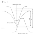
- Figure 4 is the moving path in a basic section perpendicular to the axis in the case of negative deviation of a tooth of the cup-shaped flexible external gear relative to the rigid internal gear in a flexible meshing type gear device.
- Figure 5 is a diagram for explaining the method of tooth profile derivation of this invention.
- Figure 6 is a diagram for explaining the meshing of conventional countermovement type tooth profiles.
- Figure 7 is an explanatory diagram of the meshing of the tooth profiles of this invention in a basic section perpendicular to the tooth, drawn relatively with respect to one tooth space of the rigid internal gear followed over the passage of time.
- Figure 8 is an explanatory diagram of the meshing of the tooth profiles of this invention in a basic section perpendicular to the tooth, drawn spatially over half the teeth of the rigid internal gear.
- Figure 9 is a set of diagrams for explaining meshing of the tooth profiles of this invention in basic sections other than that perpendicular to the tooth, in which (a) is for a section on the opening side of the basic section perpendicular to the tooth, (b) shows the case of applying relieving thereto, (c) is for a section on the diaphragm side of the basic section perpendicular to the tooth, and (d) shows the case of applying reverse relieving thereto.
- Figure 10 is a set of diagrams for explaining correction applied to the teeth of the cup-shaped flexible external gear, in which (a) is a diagram showing relieving applied on the opening side of a basic section perpendicular to the tooth and (b) is a diagram showing reverse relieving further applied on the diaphragm side of the basic section perpendicular to the tooth.
- FIGs 1 and 2 are perspective and front views of a prior-art flexible meshing type gear device to which this invention can be applied.
- This flexible meshing type gear device 1 comprises a cylindrical rigid internal gear 2, a cup-shaped flexible external gear 3 disposed inside the rigid internal gear 2, and a elliptical wave generator 4 fitted inside the cup-shaped flexible external gear 3.
- the cup-shaped flexible external gear 3 is in a flexed state produced by the wave generator 4.
- Figure 3 shows the flexed state in sections through the axis of the cup-shaped flexible external gear 3 caused so-called coning, namely, by flexing the opening portion of the flexible external gear.
- Figure 3(a) shows the state before deformation
- (b) is a section through the axis including the major axis of the wave generator 4
- (c) is a section through the axis including the minor axis thereof.
- the amount of flexing produced in the cup-shaped flexible external gear 3 is maximum at the opening portion 3a and gradually decreases toward the side of a diaphragm 3b.
- Figure 4 shows the moving path L of a tooth of the cup-shaped flexible external gear with respect to the rigid internal gear in a basic section perpendicular to the tooth of the flexible external gear (a section perpendicular to the axis for considering the moving path used to derive the tooth profile; normally taken as the section at the center of the tooth trace) in the case where the amount of flexing (difference between the major and minor axes of the ellipse produced by deformation of the pitch circle of the flexible external gear) is ⁇ ( ⁇ ⁇ 1) times the normal value d , i.e., ⁇ d. This is the so-called negative deflection state.
- the phase is inverted vertically from that of the moving path of the external gear in prior-art devices of this type.
- Figure 5 is a diagram for explaining the method of tooth profile derivation of this invention.
- Point A is the upper (deeper in the tooth space of the rigid internal gear) limiting point of meshing an the moving path L.
- Point B is the lower limiting point of the curved portion of the path which is convex with respect to the rigid internal gear.
- Curve AC is obtained by similarity transformation of the curve of the path between A and B at a reduction ratio ⁇ using point A as the origin (center of similarity) and this curve AC is adopted as the tooth profile of the flexible external gear. This tooth profile is therefore convex.
- curve AD is obtained by similarity transformation of curve AB at an enlargement ratio (1 + ⁇ ) using point A as the origin and this curve AD is adopted as the tooth profile of the rigid internal gear.
- This tooth profile is therefore concave.
- point B is defined beforehand within the range in which intersection with the tooth profile on the opposite side does not occur.
- Figure 6 shows a contrasting example of countermovement meshing in an earlier invention of the inventor. It is well known that pass meshing is superior from the viewpoint of retention of lubricating oil.
- Figure 7 shows the meshing of the tooth profiles of this invention drawn relatively with respect to one tooth space of the rigid internal gear followed over the passage of time.
- Figure 8 shows the meshing drawn spatially over half the teeth. From Figure 8 it can further be seen that the meshing region excludes the vicinity of the major axis. This, taken in light of the fact that the bending stress accompanying the elliptical deformation is greatest at the major axis, indicates that the present tooth profile is also superior in the aspect of maintaining rim strength.
- this invention when applied to a device equipped with a cup-shaped flexible external gear, it can be applied independently of the coning angle of the flexible external gear. As a result, the invention has the merit of being applicable without modification to types having cup-shaped flexible external gears of short body length.
Landscapes
- Engineering & Computer Science (AREA)
- General Engineering & Computer Science (AREA)
- Mechanical Engineering (AREA)
- Retarders (AREA)
- Gears, Cams (AREA)
Claims (3)
- Zahnradanordnung (1) vom flexibel kämmenden Typ mit Passier-Zahnprofil und mit einem starren innenverzahnten Rad (2), einem flexiblen außenverzahnten Rad (3) in dem innenverzahnten Rad (2) und einem Wellengenerator (4) zum Biegen des außenverzahnten Rades (3) zu einer elliptischen Querschnittform, was ein teilweises Kämmen des außenverzahnten Rades (3) mit dem starren innenverzahnten Rad (2) und ein Rotieren der Kämmposition der zwei Zahnräder (2; 3) in Umfangsrichtung bewirkt. wobei das Rotieren des Wellengenerators (4) eine Relativdrehung zwischen den zwei Zahnrädern (2; 3) hervorruft, wobei die Zahnradanordnung (1) vom flexibel kämmenden Typ dadurch gekennzeichnet ist, daß(a) das starre innenverzahnte Rad (2) und das flexible außenverzahnte Rad (3) beide Stirnräder sind,(b) die Zähnezahl des flexiblen außenverzahnten Rads (3) um zwei größer als die des starren innenverzahnten Rads (2) ist,(c) das Zahnprofil des flexiblen außenverzahnten Rads (3) konvex ist und dessen Gestalt die einer Kurve ist, die man erhält, indem man einen Zahnradzahnbereich, der an dem Bewegungsweg, den das außenverzahnte Rad (3) relativ zu dem innenverzahnten Rad (2) beschreibt, wie er durch eine Zahnstangennäherung festgelegt ist, relativ zu dem innverzahnten Rad (2) konvex ist, einer Ähnlichkeitstransformation bei einem Reduktionsverhältnis (λ) unter Verwendung des Grenzpunktes für den Kontakt zwischen den zwei Zahnrädern (2; 3) auf dem Weg als Ursprung unterwirft, und(d) das Zahnprofil des starren innenverzahnten Rads (2) konkav ist und dessen Gestalt die einer Kurve ist, die man erhält, indem man den gleichen Bereich, der relativ zu dem innenverzahnten Rad (2) an dem Bewegungsweg konvex ist, einer Ähnlichkeitstransformation mit einem Vergrößerungsverhältnis (1 + λ) unter Verwendung des Grenzpunktes als Ursprung unterwirft, wodurch das Kämmen der zwei Zahnräder (2; 3) einen kontinuierlichen Kontakt beibehält und vom Passier-Typ ist.
- Zahnradanordnung vom flexibel kämmenden Typ nach Anspruch 1, wobei das flexible außenverzahnte Rad (3) becherförmig ist und der Wellengenerator (4) daran angepaßt ist, das außenverzahnte Rad (3) in eine elliptische Schnittgestalt zu biegen, so daß das Maß der in dem außenverzahnten Rad (3) hervorgerufenen Verformung von einer Diaphragmaseite davon in Richtung auf einen Öffnungsbereich davon annähernd im Verhältnis zu dem Abstand von dem Diaphragma zunimmt, wobei das Zahnprofil des becherförmigen. flexiblen, außenverzahnten Rads (3) konvex ist und dessen Gestalt die einer Kurve ist, die man erhält, indem man einen Zahnradzahnbereich, der an dem Bewegungsweg, den das außenverzahnte Rad (3) relativ zu dem innenverzahnten Rad (2) in einem Basisschnitt der Flankenlinie beschreibt, wie er durch eine Zahnstangennäherung bestimmt wird, relativ zu dem innenverzahnten Rad (2) konvex ist, einer Ähnlichkeitstransformation mit einem Reduktionsverhältnis (λ) unter Verwendung des Grenzpunktes des Kontakts zwischen den zwei Zahnrädern (2; 3) an dem Weg als den Ursprung unterwirft, und
wobei Zähne des becherförmigen, flexiblen, außenverzahnten Rads (3) mit einer Entlastungsformgebung in Richtung zu der Öffnungsseite von dem Basisschnitt der Flankenlinie versehen sind. - Zahnradanordnung (1) vom flexibel kämmenden Typ mit Passier-Zahnprofil gemäß Anspruch 2, wobei Zähne des becherförmigen, flexiblen, außenverzahnten Rads (3) mit einer umgekehrten Entlastungsformgebung in Richtung zu der Diaphragmaseite von dem Basisschnitt der Flankenlinie versehen sind.
Applications Claiming Priority (3)
| Application Number | Priority Date | Filing Date | Title |
|---|---|---|---|
| JP10444194A JP3441160B2 (ja) | 1994-04-19 | 1994-04-19 | 追い越し接触型歯形の撓み噛み合い式歯車装置 |
| JP104441/94 | 1994-04-19 | ||
| PCT/JP1995/000738 WO1995028583A1 (en) | 1994-04-19 | 1995-04-14 | Flexible meshing type gear device with a passing tooth profile |
Publications (3)
| Publication Number | Publication Date |
|---|---|
| EP0703385A1 EP0703385A1 (de) | 1996-03-27 |
| EP0703385A4 EP0703385A4 (de) | 1996-08-28 |
| EP0703385B1 true EP0703385B1 (de) | 1999-01-27 |
Family
ID=14380751
Family Applications (1)
| Application Number | Title | Priority Date | Filing Date |
|---|---|---|---|
| EP95915326A Expired - Lifetime EP0703385B1 (de) | 1994-04-19 | 1995-04-14 | Harmonisches getriebe mit zahnprofil für durchgehenden eingriff |
Country Status (8)
| Country | Link |
|---|---|
| US (1) | US5687620A (de) |
| EP (1) | EP0703385B1 (de) |
| JP (1) | JP3441160B2 (de) |
| KR (1) | KR100360925B1 (de) |
| CA (1) | CA2165571C (de) |
| DE (1) | DE69507559T2 (de) |
| TW (1) | TW324488U (de) |
| WO (1) | WO1995028583A1 (de) |
Families Citing this family (20)
| Publication number | Priority date | Publication date | Assignee | Title |
|---|---|---|---|---|
| JP3768261B2 (ja) * | 1995-05-19 | 2006-04-19 | 株式会社ハーモニック・ドライブ・システムズ | 偏平型波動歯車装置 |
| JP4357054B2 (ja) * | 1999-11-22 | 2009-11-04 | 株式会社ハーモニック・ドライブ・システムズ | 追い越し型極大歯たけの歯形を有する負偏位撓みかみ合い式歯車装置 |
| JP2003176857A (ja) * | 2001-12-11 | 2003-06-27 | Teijin Seiki Co Ltd | 噛み合い式歯車装置用フレクススプラインおよびそのフレクススプラインを備えた噛み合い式歯車装置 |
| US7328632B2 (en) | 2003-10-30 | 2008-02-12 | Harmonic Drive Systems Inc. | Wave gear drive having widely engaging tooth profile |
| JP4650953B2 (ja) * | 2004-06-07 | 2011-03-16 | 株式会社ハーモニック・ドライブ・システムズ | 高ラチェティングトルク歯形を有する波動歯車装置 |
| US7735396B2 (en) | 2004-06-21 | 2010-06-15 | Harmonic Drive Systems Inc. | Wave gear drive having negative deflection meshing tooth profile |
| US8028603B2 (en) * | 2007-12-04 | 2011-10-04 | Harmonic Drive Systems Inc. | Method for setting gear tooth profile in flat wave gear device on side where gears have same number of teeth |
| WO2010023710A1 (ja) * | 2008-08-29 | 2010-03-04 | 株式会社ハーモニック・ドライブ・システムズ | 正偏位噛み合い複合歯形を有する波動歯車装置 |
| WO2010070712A1 (ja) * | 2008-12-18 | 2010-06-24 | 株式会社ハーモニック・ドライブ・システムズ | 3次元接触可能な転位歯形を有する波動歯車装置 |
| JP5275150B2 (ja) * | 2009-06-23 | 2013-08-28 | 株式会社ハーモニック・ドライブ・システムズ | 波動歯車装置 |
| WO2012153363A1 (ja) * | 2011-05-09 | 2012-11-15 | 株式会社ハーモニック・ドライブ・システムズ | 3次元連続接触歯形を有する波動歯車装置 |
| JP5456941B1 (ja) * | 2012-08-17 | 2014-04-02 | 株式会社ハーモニック・ドライブ・システムズ | 3次元接触歯形を有する波動歯車装置 |
| CN103939575B (zh) * | 2014-04-10 | 2016-05-11 | 重庆大学 | 基于共轭曲线的点接触齿轮、啮合副及其加工刀具 |
| WO2016092636A1 (ja) | 2014-12-09 | 2016-06-16 | 株式会社ハーモニック・ドライブ・システムズ | 追い越し型かみ合いの負偏位波動歯車装置 |
| US11092224B2 (en) | 2017-10-10 | 2021-08-17 | Hamilton Sundstrand Corporation | Method of developing spline profile |
| JP2019199893A (ja) | 2018-05-14 | 2019-11-21 | セイコーエプソン株式会社 | ロボット、歯車装置および歯車装置ユニット |
| USD937332S1 (en) * | 2020-06-30 | 2021-11-30 | Harmonic Drive Systems Inc. | Speed reducer |
| USD971978S1 (en) * | 2020-09-09 | 2022-12-06 | Harmonic Drive Systems Inc. | Speed reducer |
| US12209648B2 (en) * | 2021-06-01 | 2025-01-28 | Harmonic Drive Systems Inc. | Tooth profile designing method for strain wave gearing |
| CN117772808B (zh) * | 2024-02-23 | 2024-05-10 | 太原理工大学 | 一种校准异速比的齿轮装置及异步轧机 |
Family Cites Families (10)
| Publication number | Priority date | Publication date | Assignee | Title |
|---|---|---|---|---|
| US2906143A (en) * | 1955-03-21 | 1959-09-29 | United Shoe Machinery Corp | Strain wave gearing |
| EP0113375B1 (de) * | 1982-06-18 | 1987-09-09 | Matsushita Electric Industrial Co., Ltd. | Übersetzungsgetriebe |
| JPH0784896B2 (ja) * | 1986-11-05 | 1995-09-13 | 株式会社ハーモニック・ドライブ・システムズ | 撓み噛み合い式歯車装置 |
| JP2503027B2 (ja) * | 1987-09-21 | 1996-06-05 | 株式会社ハーモニック・ドライブ・システムズ | 撓みかみ合い式歯車装置 |
| JP2612591B2 (ja) * | 1988-05-18 | 1997-05-21 | 株式会社ハーモニック・ドライブ・システムズ | たわみ噛み合い式歯車装置 |
| JP2535503Y2 (ja) * | 1991-05-20 | 1997-05-14 | 株式会社ハーモニック・ドライブ・システムズ | カップ型歯車式調和変速装置における外歯および内歯の噛み合わせ構造 |
| JP3230595B2 (ja) * | 1991-12-24 | 2001-11-19 | 株式会社ハーモニック・ドライブ・システムズ | 撓み噛み合い式歯車装置の3次元無転位歯形の形成方法 |
| JP3230596B2 (ja) * | 1991-12-24 | 2001-11-19 | 株式会社ハーモニック・ドライブ・システムズ | 撓み噛み合い式歯車装置の3次元無転位歯形の形成方法 |
| EP0693640B1 (de) * | 1992-06-03 | 1998-02-25 | Sumitomo Heavy Industries, Ltd. | Zykloidgetriebe des Typs mit elastischem Zahnrad |
| EP0622565B1 (de) * | 1992-11-24 | 1997-02-05 | Harmonic Drive Systems Inc. | Flexible kontaktverzahnung mit tertiärer negativ-deformation und einem nicht profilverschobenen zahnprofil |
-
1994
- 1994-04-19 JP JP10444194A patent/JP3441160B2/ja not_active Expired - Lifetime
-
1995
- 1995-04-14 CA CA002165571A patent/CA2165571C/en not_active Expired - Lifetime
- 1995-04-14 WO PCT/JP1995/000738 patent/WO1995028583A1/ja not_active Ceased
- 1995-04-14 KR KR1019950705793A patent/KR100360925B1/ko not_active Expired - Lifetime
- 1995-04-14 DE DE69507559T patent/DE69507559T2/de not_active Expired - Lifetime
- 1995-04-14 US US08/564,209 patent/US5687620A/en not_active Expired - Lifetime
- 1995-04-14 EP EP95915326A patent/EP0703385B1/de not_active Expired - Lifetime
- 1995-05-03 TW TW085213233U patent/TW324488U/zh unknown
Also Published As
| Publication number | Publication date |
|---|---|
| KR960703213A (ko) | 1996-06-19 |
| EP0703385A4 (de) | 1996-08-28 |
| KR100360925B1 (ko) | 2003-04-10 |
| JP3441160B2 (ja) | 2003-08-25 |
| TW324488U (en) | 1998-01-01 |
| DE69507559T2 (de) | 1999-09-02 |
| US5687620A (en) | 1997-11-18 |
| JPH07293643A (ja) | 1995-11-07 |
| CA2165571C (en) | 2005-03-29 |
| WO1995028583A1 (en) | 1995-10-26 |
| DE69507559D1 (de) | 1999-03-11 |
| CA2165571A1 (en) | 1995-10-26 |
| EP0703385A1 (de) | 1996-03-27 |
Similar Documents
| Publication | Publication Date | Title |
|---|---|---|
| EP0703385B1 (de) | Harmonisches getriebe mit zahnprofil für durchgehenden eingriff | |
| US5782143A (en) | Flexible meshing type gear device with negative deflection passing tooth profile | |
| US6526849B1 (en) | Negative deflection flexible meshing type gear device having passing tooth profile with maximized tooth height | |
| JP5913378B2 (ja) | リム厚を考慮したインボリュート正偏位歯形を有する波動歯車装置 | |
| JPWO1996019683A1 (ja) | 負偏位追い越し歯形の撓み噛み合い式歯車装置 | |
| US8776638B2 (en) | Wave gear device having three-dimensionally contactable shifted tooth profile | |
| US7328632B2 (en) | Wave gear drive having widely engaging tooth profile | |
| US6467375B1 (en) | Flexible meshing type gear device having deflection meshing involute tooth profile | |
| US7735396B2 (en) | Wave gear drive having negative deflection meshing tooth profile | |
| US9903459B2 (en) | Strain wave gearing having continuous-contact tooth profile formed using arcuate tooth profile | |
| US20070180947A1 (en) | Wave gear drive with continuous meshing, high ratcheting torque tooth profile | |
| US5485766A (en) | Tertiary negative-deviation flexing contact type gear drive of non-profile-shifted tooth profile | |
| EP3306132B1 (de) | Spannungswellengetriebevorrichtung mit zusammengesetztem ineinandergreifen mit folgerichtigkeit der zahnoberflächen | |
| WO2012104927A1 (ja) | 3次元接触のインボリュート正偏位歯形を有する波動歯車装置 | |
| EP0622566A1 (de) | Flexible kobtaktverzahnung mit nicht profilverschobenen aus zwei kreisbögen generierten zahnprofil | |
| JP4392787B2 (ja) | 広域3次元かみ合い歯形を有する波動歯車装置 | |
| US3768326A (en) | Orthogonal skew-axis gearing | |
| US10174825B2 (en) | Passing-type-meshing negative-deflection strain wave gearing | |
| KR102860650B1 (ko) | 파동기어장치의 치형설계방법 | |
| JPWO1994012809A1 (ja) | 無転位2円弧複合歯形の撓み噛み合い式歯車装置 |
Legal Events
| Date | Code | Title | Description |
|---|---|---|---|
| PUAI | Public reference made under article 153(3) epc to a published international application that has entered the european phase |
Free format text: ORIGINAL CODE: 0009012 |
|
| 17P | Request for examination filed |
Effective date: 19951218 |
|
| AK | Designated contracting states |
Kind code of ref document: A1 Designated state(s): CH DE ES FR GB IT LI NL SE |
|
| A4 | Supplementary search report drawn up and despatched | ||
| AK | Designated contracting states |
Kind code of ref document: A4 Designated state(s): CH DE ES FR GB IT LI NL SE |
|
| 17Q | First examination report despatched |
Effective date: 19970905 |
|
| GRAG | Despatch of communication of intention to grant |
Free format text: ORIGINAL CODE: EPIDOS AGRA |
|
| GRAG | Despatch of communication of intention to grant |
Free format text: ORIGINAL CODE: EPIDOS AGRA |
|
| GRAH | Despatch of communication of intention to grant a patent |
Free format text: ORIGINAL CODE: EPIDOS IGRA |
|
| GRAH | Despatch of communication of intention to grant a patent |
Free format text: ORIGINAL CODE: EPIDOS IGRA |
|
| GRAA | (expected) grant |
Free format text: ORIGINAL CODE: 0009210 |
|
| AK | Designated contracting states |
Kind code of ref document: B1 Designated state(s): CH DE ES FR GB IT LI NL SE |
|
| PG25 | Lapsed in a contracting state [announced via postgrant information from national office to epo] |
Ref country code: SE Free format text: THE PATENT HAS BEEN ANNULLED BY A DECISION OF A NATIONAL AUTHORITY Effective date: 19990127 Ref country code: NL Free format text: LAPSE BECAUSE OF FAILURE TO SUBMIT A TRANSLATION OF THE DESCRIPTION OR TO PAY THE FEE WITHIN THE PRESCRIBED TIME-LIMIT Effective date: 19990127 Ref country code: LI Free format text: LAPSE BECAUSE OF FAILURE TO SUBMIT A TRANSLATION OF THE DESCRIPTION OR TO PAY THE FEE WITHIN THE PRESCRIBED TIME-LIMIT Effective date: 19990127 Ref country code: IT Free format text: LAPSE BECAUSE OF FAILURE TO SUBMIT A TRANSLATION OF THE DESCRIPTION OR TO PAY THE FEE WITHIN THE PRE;WARNING: LAPSES OF ITALIAN PATENTS WITH EFFECTIVE DATE BEFORE 2007 MAY HAVE OCCURRED AT ANY TIME BEFORE 2007. THE CORRECT EFFECTIVE DATE MAY BE DIFFERENT FROM THE ONE RECORDED.SCRIBED TIME-LIMIT Effective date: 19990127 Ref country code: FR Free format text: LAPSE BECAUSE OF FAILURE TO SUBMIT A TRANSLATION OF THE DESCRIPTION OR TO PAY THE FEE WITHIN THE PRESCRIBED TIME-LIMIT Effective date: 19990127 Ref country code: ES Free format text: THE PATENT HAS BEEN ANNULLED BY A DECISION OF A NATIONAL AUTHORITY Effective date: 19990127 Ref country code: CH Free format text: LAPSE BECAUSE OF FAILURE TO SUBMIT A TRANSLATION OF THE DESCRIPTION OR TO PAY THE FEE WITHIN THE PRESCRIBED TIME-LIMIT Effective date: 19990127 |
|
| REG | Reference to a national code |
Ref country code: CH Ref legal event code: EP |
|
| REF | Corresponds to: |
Ref document number: 69507559 Country of ref document: DE Date of ref document: 19990311 |
|
| PG25 | Lapsed in a contracting state [announced via postgrant information from national office to epo] |
Ref country code: GB Free format text: LAPSE BECAUSE OF NON-PAYMENT OF DUE FEES Effective date: 19990427 |
|
| EN | Fr: translation not filed | ||
| NLV1 | Nl: lapsed or annulled due to failure to fulfill the requirements of art. 29p and 29m of the patents act | ||
| REG | Reference to a national code |
Ref country code: CH Ref legal event code: PL |
|
| PLBE | No opposition filed within time limit |
Free format text: ORIGINAL CODE: 0009261 |
|
| STAA | Information on the status of an ep patent application or granted ep patent |
Free format text: STATUS: NO OPPOSITION FILED WITHIN TIME LIMIT |
|
| GBPC | Gb: european patent ceased through non-payment of renewal fee |
Effective date: 19990427 |
|
| 26N | No opposition filed | ||
| PGFP | Annual fee paid to national office [announced via postgrant information from national office to epo] |
Ref country code: DE Payment date: 20140626 Year of fee payment: 20 |
|
| REG | Reference to a national code |
Ref country code: DE Ref legal event code: R071 Ref document number: 69507559 Country of ref document: DE |
|
| REG | Reference to a national code |
Ref country code: DE Ref legal event code: R071 Ref document number: 69507559 Country of ref document: DE |