EP0703393A1 - Dispositif de surveillance de levée d'une soupape à diaphragme - Google Patents
Dispositif de surveillance de levée d'une soupape à diaphragme Download PDFInfo
- Publication number
- EP0703393A1 EP0703393A1 EP95114625A EP95114625A EP0703393A1 EP 0703393 A1 EP0703393 A1 EP 0703393A1 EP 95114625 A EP95114625 A EP 95114625A EP 95114625 A EP95114625 A EP 95114625A EP 0703393 A1 EP0703393 A1 EP 0703393A1
- Authority
- EP
- European Patent Office
- Prior art keywords
- switching
- spindle
- valve
- cams
- limit switches
- Prior art date
- Legal status (The legal status is an assumption and is not a legal conclusion. Google has not performed a legal analysis and makes no representation as to the accuracy of the status listed.)
- Granted
Links
- 230000001939 inductive effect Effects 0.000 claims description 2
- 238000005259 measurement Methods 0.000 claims description 2
- 238000012544 monitoring process Methods 0.000 claims description 2
- 238000011109 contamination Methods 0.000 description 2
- 230000006978 adaptation Effects 0.000 description 1
- 230000008878 coupling Effects 0.000 description 1
- 238000010168 coupling process Methods 0.000 description 1
- 238000005859 coupling reaction Methods 0.000 description 1
- 230000001419 dependent effect Effects 0.000 description 1
- 238000011161 development Methods 0.000 description 1
- 230000018109 developmental process Effects 0.000 description 1
- 238000006073 displacement reaction Methods 0.000 description 1
Images

Classifications
-
- F—MECHANICAL ENGINEERING; LIGHTING; HEATING; WEAPONS; BLASTING
- F16—ENGINEERING ELEMENTS AND UNITS; GENERAL MEASURES FOR PRODUCING AND MAINTAINING EFFECTIVE FUNCTIONING OF MACHINES OR INSTALLATIONS; THERMAL INSULATION IN GENERAL
- F16K—VALVES; TAPS; COCKS; ACTUATING-FLOATS; DEVICES FOR VENTING OR AERATING
- F16K37/00—Special means in or on valves or other cut-off apparatus for indicating or recording operation thereof, or for enabling an alarm to be given
- F16K37/0025—Electrical or magnetic means
- F16K37/0041—Electrical or magnetic means for measuring valve parameters
-
- Y—GENERAL TAGGING OF NEW TECHNOLOGICAL DEVELOPMENTS; GENERAL TAGGING OF CROSS-SECTIONAL TECHNOLOGIES SPANNING OVER SEVERAL SECTIONS OF THE IPC; TECHNICAL SUBJECTS COVERED BY FORMER USPC CROSS-REFERENCE ART COLLECTIONS [XRACs] AND DIGESTS
- Y10—TECHNICAL SUBJECTS COVERED BY FORMER USPC
- Y10T—TECHNICAL SUBJECTS COVERED BY FORMER US CLASSIFICATION
- Y10T137/00—Fluid handling
- Y10T137/8158—With indicator, register, recorder, alarm or inspection means
- Y10T137/8225—Position or extent of motion indicator
- Y10T137/8242—Electrical
-
- Y—GENERAL TAGGING OF NEW TECHNOLOGICAL DEVELOPMENTS; GENERAL TAGGING OF CROSS-SECTIONAL TECHNOLOGIES SPANNING OVER SEVERAL SECTIONS OF THE IPC; TECHNICAL SUBJECTS COVERED BY FORMER USPC CROSS-REFERENCE ART COLLECTIONS [XRACs] AND DIGESTS
- Y10—TECHNICAL SUBJECTS COVERED BY FORMER USPC
- Y10T—TECHNICAL SUBJECTS COVERED BY FORMER US CLASSIFICATION
- Y10T137/00—Fluid handling
- Y10T137/8158—With indicator, register, recorder, alarm or inspection means
- Y10T137/8359—Inspection means
Definitions
- the invention relates to a device for monitoring the valve lift of a pneumatically or hydraulically driven valve having a valve body that can be actuated via a pressure spindle, in particular a diaphragm valve, wherein a switching spindle is operatively connected to the pressure spindle and a switching cam on the switching spindle for actuating two as signal transmitters for two valve positions serving limit switches is set.
- So-called electrical feedback of the type mentioned above are used to display the valve position in connection with pneumatically or hydraulically driven globe valves.
- the limit switches are actuated in each of the two end positions of the valve lift, as a result of which an electrical signal corresponding to the open or closed position of the valve is generated.
- This electrical signal can then be passed on, for example, to a controller or a control panel.
- the inventor has set himself the task of creating a device of the type mentioned at the beginning create, in which the required adjustment to the valve lift can be made in a simple manner.
- two switching cams can be positioned at a distance from one another on the switching spindle, and a switching cam is assigned to each limit switch.
- the switching cams are preferably placed in such a clamping manner on the switching spindle that, on the one hand, displacement by the limit switches is not possible, but, on the other hand, the position can be changed without too much effort.
- a crossbar acting as a driver is arranged between the switching cams for positioning the switching cams.
- the switching cams are automatically moved into their correct working position when the valve is first opened and closed.
- the switching cam is automatically readjusted to indicate the closed position of the valve even when the medium diaphragm is set during storage or operation of the valve drive.
- the switching spindle is coupled to the pressure spindle.
- the device is preferably designed such that it can be screwed into the housing cover of a valve housing.
- the feedback sensor is preferably enclosed by a transparent cover hood.
- This can be provided with a scale for the visible measurement of the valve lift.
- the switching cams are expediently made of preferably red plastic.
- the limit switches can be designed as microswitches, inductive proximity switches or other suitable switching elements and are preferably arranged symmetrically to one another and in an unchangeable position with respect to the axis of the switching spindle.
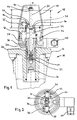
- a valve housing 10 of a diaphragm valve has, according to FIG. 1, a housing cover 12, in which a threaded bushing 14 is arranged centrally.
- a feedback 18 with a switching spindle 20 is mounted on the valve housing 10 .
- the feedback unit 18 is screwed into the threaded bushing 14 via a centrally arranged screw part 24 with an external thread 26.
- the switching spindle 20 passes through the screw 24 in the direction of the actuation axis z.
- the screw part 24 is overlapped by a support part 28 which can be fixed by means of an adjusting screw 30.
- Mounting walls 32 which are arranged parallel to the axis direction z and to which limit switches 34, 35 are fixed symmetrically, protrude from this carrier part 28.
- the two assembly walls 32 are connected to one another via a transverse web 36 lying perpendicular to the axial direction z.
- two switching cams 38, 40 are slidably fastened and are at a distance a from one another after the diaphragm valve has been started up.
- the cross piece 36 lies between the two switching cams 38, 40 and, according to FIG. 2, partially wraps around the switching spindle 20 such that it can act as a driver for the switching cams 38, 40.
- the switching cam 38 controls the limit switch 34 indicating the open position of the valve
- the switching cam 40 controls the limit switch 35 indicating the closed position of the valve.
- the switching rollers 44 of the limit switches 34, 35 run on the switching spindle 20 during valve actuation and become over conical surfaces when the valve end position is reached 42 raised to the switching cams 38.40.
- a switching pin 46 is actuated, which triggers a corresponding electrical signal.
- the indicator 18 is provided with a transparent cover 48 overlapping the carrier part 28 for protection against contamination.
- a channel with a device plug 50 is arranged on the side of the carrier part 28 to lead the electrical connecting cables out of the feedback unit 18.
- 3a-c show the positions of the two switching cams 38, 40 on the switching spindle 20 during the first opening and closing of the valve.
- FIG 3a shows the starting position after the feedback sensor 18 has been screwed onto the valve housing 10.
- the two switching cams 38, 40 are pushed by hand onto the crossbar 36 on both sides.
- the valve is closed for the first time. Due to the driving action of the cross piece 36, the switching cam 40 is displaced into its final position during the closing movement of the valve.
- 3c shows the position of the switching cams 38, 40 after the valve has reached its open position for the first time. During this valve movement executing the maximum valve lift h, the second switching cam 38 has also been displaced into its final position.
Landscapes
- Engineering & Computer Science (AREA)
- General Engineering & Computer Science (AREA)
- Mechanical Engineering (AREA)
- Indication Of The Valve Opening Or Closing Status (AREA)
- Fluid-Driven Valves (AREA)
- Mechanically-Actuated Valves (AREA)
- Valve-Gear Or Valve Arrangements (AREA)
Applications Claiming Priority (2)
| Application Number | Priority Date | Filing Date | Title |
|---|---|---|---|
| CH02862/94A CH688942A5 (de) | 1994-09-21 | 1994-09-21 | Vorrichtung zur Ueberwachung des Ventilhubs eines Membranventils. |
| CH2862/94 | 1994-09-21 |
Publications (2)
| Publication Number | Publication Date |
|---|---|
| EP0703393A1 true EP0703393A1 (fr) | 1996-03-27 |
| EP0703393B1 EP0703393B1 (fr) | 1998-12-16 |
Family
ID=4243261
Family Applications (1)
| Application Number | Title | Priority Date | Filing Date |
|---|---|---|---|
| EP95114625A Expired - Lifetime EP0703393B1 (fr) | 1994-09-21 | 1995-09-18 | Dispositif de surveillance de levée d'une soupape |
Country Status (9)
| Country | Link |
|---|---|
| US (1) | US5685336A (fr) |
| EP (1) | EP0703393B1 (fr) |
| JP (1) | JP2880671B2 (fr) |
| KR (1) | KR100211779B1 (fr) |
| AT (1) | ATE174673T1 (fr) |
| CH (1) | CH688942A5 (fr) |
| DE (1) | DE59504545D1 (fr) |
| ES (1) | ES2126191T3 (fr) |
| TW (1) | TW347037U (fr) |
Cited By (1)
| Publication number | Priority date | Publication date | Assignee | Title |
|---|---|---|---|---|
| EP1985902A1 (fr) * | 2007-04-26 | 2008-10-29 | Barksdale, Inc. | Indicateur de position de valve |
Families Citing this family (18)
| Publication number | Priority date | Publication date | Assignee | Title |
|---|---|---|---|---|
| DE19917698A1 (de) * | 1999-04-20 | 2000-10-26 | Fischer Georg Rohrleitung | Ventilanordnung |
| KR100336397B1 (ko) * | 2000-04-06 | 2002-05-10 | 석진철 | 모터형 밸브구동기용 밸브개폐 표시장치 |
| EP1390651A4 (fr) | 2001-04-19 | 2005-12-07 | Asco Controls Lp | Indicateur lineaire pour soupape |
| US6895130B1 (en) | 2002-02-12 | 2005-05-17 | Tobi Mengle | True position sensor for diaphragm valves using reflected light property variation |
| US20040011408A1 (en) * | 2002-07-17 | 2004-01-22 | Kidde Fire Fighting Inc. | Pressure reducing valve apparatus and method of the same |
| US20050150560A1 (en) * | 2004-01-08 | 2005-07-14 | Jerry Amato | Diaphragm valve |
| KR100666155B1 (ko) * | 2005-07-11 | 2007-01-09 | 한국오발주식회사 | 밸브 조작기 제어용 오픈 토르크 리미터 |
| US9341281B2 (en) | 2007-02-12 | 2016-05-17 | Colt Irrigation Llc | Fluid activated flow control apparatus |
| US8397745B2 (en) | 2007-02-12 | 2013-03-19 | Colt Irrigation, LLC | Fluid activated flow control apparatus |
| JP5049661B2 (ja) * | 2007-06-11 | 2012-10-17 | 日本ダイヤバルブ株式会社 | ダイヤフラム弁のリミットスイッチ作動機構 |
| DE102010050662A1 (de) * | 2010-11-09 | 2012-05-10 | Festo Ag & Co. Kg | Steuerkopf für ein fluidisch ansteuerbares Ventil |
| CN102537487B (zh) * | 2010-12-24 | 2014-02-12 | 秦皇岛秦冶重工有限公司 | 一种阀门驱动装置 |
| US9341283B2 (en) * | 2013-09-18 | 2016-05-17 | Itt Manufacturing Enterprises Llc. | Self setting and stabilized switch target |
| US10571937B1 (en) | 2014-01-23 | 2020-02-25 | Colt Irrigation, LLC | Valve control apparatus |
| US9599286B2 (en) | 2014-01-23 | 2017-03-21 | Colt Irrigation, LLC | Fluid activated flow control apparatus |
| US10088849B2 (en) | 2014-01-23 | 2018-10-02 | Colt Irrigation, LLC | Fluid activated flow control apparatus |
| DE102015105483B4 (de) | 2015-04-10 | 2023-07-06 | Bürkert Werke GmbH | Ventilantrieb |
| US11067199B2 (en) * | 2018-11-06 | 2021-07-20 | L6 Inc. | Pressure relief valve lift indicator |
Citations (6)
| Publication number | Priority date | Publication date | Assignee | Title |
|---|---|---|---|---|
| GB1116040A (en) * | 1965-08-27 | 1968-06-06 | Marvin Henry Grove | Improvements in or relating to electrical position responsive apparatus |
| US3802462A (en) * | 1971-08-18 | 1974-04-09 | Fischer Ag Georg | Remotely or manually operable membrane valve |
| DD132288A1 (de) * | 1977-04-25 | 1978-09-20 | Dietrich Richter | Vorrichtung zur stellungsanzeige und signalisation an absperrarmaturen |
| SU901692A1 (ru) * | 1980-03-12 | 1982-01-30 | Ворошиловградский машиностроительный институт | Привод задвижки |
| DE3509718A1 (de) * | 1985-03-18 | 1986-09-18 | Siegfried 7113 Neuenstein Böhnisch | Verteilerventil mit durchflussmesser |
| DE9409093U1 (de) * | 1994-06-03 | 1994-09-15 | ARI-Armaturen Albert Richter GmbH & Co KG, 33758 Schloß Holte-Stukenbrock | Schalt- und Meldeeinrichtung |
Family Cites Families (10)
| Publication number | Priority date | Publication date | Assignee | Title |
|---|---|---|---|---|
| US2973009A (en) * | 1959-07-23 | 1961-02-28 | Raymond J Kazyaka | Fuel control valve of a missile system |
| US3390943A (en) * | 1962-11-08 | 1968-07-02 | Honeywell Inc | Safety shut-off valve for use in a fuel transmitting conduit |
| US3189700A (en) * | 1962-12-06 | 1965-06-15 | Contromatics Corp | Valve actuator and switch |
| US3367365A (en) * | 1966-05-25 | 1968-02-06 | Orbit Valve Co | Valve |
| US3416566A (en) * | 1966-11-07 | 1968-12-17 | Acf Ind Inc | Valve operating mechanism |
| US3789875A (en) * | 1972-05-15 | 1974-02-05 | Gray Tool Co | Fluid pressure actuated valve operator |
| JPS533813B2 (fr) * | 1973-12-26 | 1978-02-10 | ||
| US4353390A (en) * | 1979-12-06 | 1982-10-12 | Anchor/Darling Valve Company | Swing check valve with internally balanced disc |
| GB8520526D0 (en) * | 1985-08-15 | 1985-09-18 | Brown Bros & Co Ltd | Sealing apparatus for fluids |
| JPH05126272A (ja) * | 1991-11-06 | 1993-05-21 | Sekisui Chem Co Ltd | バルブ用電動アクチユエータ |
-
1994
- 1994-09-21 CH CH02862/94A patent/CH688942A5/de not_active IP Right Cessation
-
1995
- 1995-08-28 TW TW087206498U patent/TW347037U/zh unknown
- 1995-09-18 DE DE59504545T patent/DE59504545D1/de not_active Expired - Lifetime
- 1995-09-18 ES ES95114625T patent/ES2126191T3/es not_active Expired - Lifetime
- 1995-09-18 AT AT95114625T patent/ATE174673T1/de active
- 1995-09-18 EP EP95114625A patent/EP0703393B1/fr not_active Expired - Lifetime
- 1995-09-20 JP JP7241638A patent/JP2880671B2/ja not_active Expired - Fee Related
- 1995-09-20 KR KR1019950030960A patent/KR100211779B1/ko not_active Expired - Fee Related
- 1995-09-21 US US08/531,761 patent/US5685336A/en not_active Expired - Lifetime
Patent Citations (6)
| Publication number | Priority date | Publication date | Assignee | Title |
|---|---|---|---|---|
| GB1116040A (en) * | 1965-08-27 | 1968-06-06 | Marvin Henry Grove | Improvements in or relating to electrical position responsive apparatus |
| US3802462A (en) * | 1971-08-18 | 1974-04-09 | Fischer Ag Georg | Remotely or manually operable membrane valve |
| DD132288A1 (de) * | 1977-04-25 | 1978-09-20 | Dietrich Richter | Vorrichtung zur stellungsanzeige und signalisation an absperrarmaturen |
| SU901692A1 (ru) * | 1980-03-12 | 1982-01-30 | Ворошиловградский машиностроительный институт | Привод задвижки |
| DE3509718A1 (de) * | 1985-03-18 | 1986-09-18 | Siegfried 7113 Neuenstein Böhnisch | Verteilerventil mit durchflussmesser |
| DE9409093U1 (de) * | 1994-06-03 | 1994-09-15 | ARI-Armaturen Albert Richter GmbH & Co KG, 33758 Schloß Holte-Stukenbrock | Schalt- und Meldeeinrichtung |
Non-Patent Citations (1)
| Title |
|---|
| SOVIET PATENTS ABSTRACTS Section PQ Week J50, 2 February 1983 Derwent World Patents Index; Class Q66, AN B1286 * |
Cited By (1)
| Publication number | Priority date | Publication date | Assignee | Title |
|---|---|---|---|---|
| EP1985902A1 (fr) * | 2007-04-26 | 2008-10-29 | Barksdale, Inc. | Indicateur de position de valve |
Also Published As
| Publication number | Publication date |
|---|---|
| ATE174673T1 (de) | 1999-01-15 |
| DE59504545D1 (de) | 1999-01-28 |
| EP0703393B1 (fr) | 1998-12-16 |
| US5685336A (en) | 1997-11-11 |
| CH688942A5 (de) | 1998-06-15 |
| KR100211779B1 (ko) | 1999-08-02 |
| ES2126191T3 (es) | 1999-03-16 |
| KR960011211A (ko) | 1996-04-20 |
| TW347037U (en) | 1998-12-01 |
| JPH08105573A (ja) | 1996-04-23 |
| JP2880671B2 (ja) | 1999-04-12 |
Similar Documents
| Publication | Publication Date | Title |
|---|---|---|
| EP0703393B1 (fr) | Dispositif de surveillance de levée d'une soupape | |
| EP0751326A2 (fr) | Dispositif pour surveiller la levée d'une soupape à diaphragme | |
| DE4411319C1 (de) | Parallelgreifer mit Spindelantrieb | |
| DE4041676A1 (de) | Einstellbarer fahrzeugscheinwerfer | |
| CH663846A5 (de) | Vorrichtung zur untersuchung von umwandlungswaermen von materialproben. | |
| EP0085383A1 (fr) | Antivol de direction à blocage hydraulique pour véhicules | |
| EP0208827B1 (fr) | Pince | |
| DE29518539U1 (de) | Positionserfassungsvorrichtung | |
| DE2851873A1 (de) | Elektronisches geraet zur pruefung der laengenabmessung von werkstuecken | |
| EP0406530A1 (fr) | Dispositif de serrage avec levier à genouillère pour la construction en carrosserie | |
| DE10003961A1 (de) | Spannvorrichtung | |
| DE4233950C2 (de) | Vorrichtung zur Bohrtiefenfeineinstellung für Säulenbohrmaschinen | |
| EP0323603B1 (fr) | Dispositif avec un détecteur de proximité pour detenir la position angulaire d'un axe | |
| DE3811110A1 (de) | Kolbenantrieb | |
| DE3141181C2 (de) | Schaltgerät mit einer kulissengeführten Schaltstange | |
| WO1992014414A1 (fr) | Dispositif d'insertion d'un instrument laparoscopique ou laparotomique dans une cavite du corps | |
| EP3378608A1 (fr) | Dispositif de manipulation et procédé de fonctionnement d'un tel dispositif | |
| EP0836959A1 (fr) | Dispositif d'émergence pour l'actionnement d'un toit coulissant | |
| DE2744779A1 (de) | Elektromechanischer regler fuer druck und temperatur | |
| DE2340980C2 (de) | Vorrichtung zum Befestigen von Druckplatten | |
| DE2724327C2 (fr) | ||
| DE4329221A1 (de) | Vorrichtung zum Einstellen von Spaltweiten im Strahlengang von Spektrometern | |
| DE4116465C2 (de) | Vorrichtung zur Verstellung eines Drehkükens in einer Rohrweiche | |
| DE3219716C2 (fr) | ||
| DE3816231C3 (de) | Rohrverzweigung mit Umschaltklappe und Stellantrieb |
Legal Events
| Date | Code | Title | Description |
|---|---|---|---|
| PUAI | Public reference made under article 153(3) epc to a published international application that has entered the european phase |
Free format text: ORIGINAL CODE: 0009012 |
|
| 17P | Request for examination filed |
Effective date: 19950918 |
|
| AK | Designated contracting states |
Kind code of ref document: A1 Designated state(s): AT CH DE ES FR GB IT LI NL |
|
| 17Q | First examination report despatched |
Effective date: 19970613 |
|
| GRAG | Despatch of communication of intention to grant |
Free format text: ORIGINAL CODE: EPIDOS AGRA |
|
| GRAG | Despatch of communication of intention to grant |
Free format text: ORIGINAL CODE: EPIDOS AGRA |
|
| GRAH | Despatch of communication of intention to grant a patent |
Free format text: ORIGINAL CODE: EPIDOS IGRA |
|
| GRAH | Despatch of communication of intention to grant a patent |
Free format text: ORIGINAL CODE: EPIDOS IGRA |
|
| GRAA | (expected) grant |
Free format text: ORIGINAL CODE: 0009210 |
|
| AK | Designated contracting states |
Kind code of ref document: B1 Designated state(s): AT CH DE ES FR GB IT LI NL |
|
| REF | Corresponds to: |
Ref document number: 174673 Country of ref document: AT Date of ref document: 19990115 Kind code of ref document: T |
|
| REG | Reference to a national code |
Ref country code: CH Ref legal event code: NV Representative=s name: ROTTMANN, ZIMMERMANN + PARTNER AG Ref country code: CH Ref legal event code: EP |
|
| GBT | Gb: translation of ep patent filed (gb section 77(6)(a)/1977) |
Effective date: 19981221 |
|
| REF | Corresponds to: |
Ref document number: 59504545 Country of ref document: DE Date of ref document: 19990128 |
|
| ET | Fr: translation filed | ||
| REG | Reference to a national code |
Ref country code: ES Ref legal event code: FG2A Ref document number: 2126191 Country of ref document: ES Kind code of ref document: T3 |
|
| PG25 | Lapsed in a contracting state [announced via postgrant information from national office to epo] |
Ref country code: ES Free format text: LAPSE BECAUSE OF NON-PAYMENT OF DUE FEES Effective date: 19990919 |
|
| PG25 | Lapsed in a contracting state [announced via postgrant information from national office to epo] |
Ref country code: LI Free format text: LAPSE BECAUSE OF NON-PAYMENT OF DUE FEES Effective date: 19990930 Ref country code: CH Free format text: LAPSE BECAUSE OF NON-PAYMENT OF DUE FEES Effective date: 19990930 |
|
| PLBE | No opposition filed within time limit |
Free format text: ORIGINAL CODE: 0009261 |
|
| STAA | Information on the status of an ep patent application or granted ep patent |
Free format text: STATUS: NO OPPOSITION FILED WITHIN TIME LIMIT |
|
| 26N | No opposition filed | ||
| PG25 | Lapsed in a contracting state [announced via postgrant information from national office to epo] |
Ref country code: NL Free format text: LAPSE BECAUSE OF NON-PAYMENT OF DUE FEES Effective date: 20000401 |
|
| REG | Reference to a national code |
Ref country code: CH Ref legal event code: PL |
|
| NLV4 | Nl: lapsed or anulled due to non-payment of the annual fee |
Effective date: 20000401 |
|
| REG | Reference to a national code |
Ref country code: GB Ref legal event code: IF02 |
|
| PGFP | Annual fee paid to national office [announced via postgrant information from national office to epo] |
Ref country code: FR Payment date: 20030904 Year of fee payment: 9 |
|
| REG | Reference to a national code |
Ref country code: ES Ref legal event code: FD2A Effective date: 20001013 |
|
| PG25 | Lapsed in a contracting state [announced via postgrant information from national office to epo] |
Ref country code: FR Free format text: LAPSE BECAUSE OF NON-PAYMENT OF DUE FEES Effective date: 20050531 |
|
| REG | Reference to a national code |
Ref country code: FR Ref legal event code: ST |
|
| PG25 | Lapsed in a contracting state [announced via postgrant information from national office to epo] |
Ref country code: IT Free format text: LAPSE BECAUSE OF NON-PAYMENT OF DUE FEES Effective date: 20050918 |
|
| PGFP | Annual fee paid to national office [announced via postgrant information from national office to epo] |
Ref country code: GB Payment date: 20120920 Year of fee payment: 18 |
|
| PGFP | Annual fee paid to national office [announced via postgrant information from national office to epo] |
Ref country code: DE Payment date: 20120921 Year of fee payment: 18 |
|
| PGFP | Annual fee paid to national office [announced via postgrant information from national office to epo] |
Ref country code: AT Payment date: 20120912 Year of fee payment: 18 |
|
| REG | Reference to a national code |
Ref country code: AT Ref legal event code: MM01 Ref document number: 174673 Country of ref document: AT Kind code of ref document: T Effective date: 20130918 |
|
| GBPC | Gb: european patent ceased through non-payment of renewal fee |
Effective date: 20130918 |
|
| REG | Reference to a national code |
Ref country code: DE Ref legal event code: R119 Ref document number: 59504545 Country of ref document: DE Effective date: 20140401 |
|
| PG25 | Lapsed in a contracting state [announced via postgrant information from national office to epo] |
Ref country code: GB Free format text: LAPSE BECAUSE OF NON-PAYMENT OF DUE FEES Effective date: 20130918 |
|
| PG25 | Lapsed in a contracting state [announced via postgrant information from national office to epo] |
Ref country code: DE Free format text: LAPSE BECAUSE OF NON-PAYMENT OF DUE FEES Effective date: 20140401 Ref country code: AT Free format text: LAPSE BECAUSE OF NON-PAYMENT OF DUE FEES Effective date: 20130918 |