EP0703455A1 - Appareil d'analyse avec dispositif de pipettage - Google Patents
Appareil d'analyse avec dispositif de pipettage Download PDFInfo
- Publication number
- EP0703455A1 EP0703455A1 EP95114811A EP95114811A EP0703455A1 EP 0703455 A1 EP0703455 A1 EP 0703455A1 EP 95114811 A EP95114811 A EP 95114811A EP 95114811 A EP95114811 A EP 95114811A EP 0703455 A1 EP0703455 A1 EP 0703455A1
- Authority
- EP
- European Patent Office
- Prior art keywords
- tip
- nozzle
- sample
- analyzing apparatus
- rack
- Prior art date
- Legal status (The legal status is an assumption and is not a legal conclusion. Google has not performed a legal analysis and makes no representation as to the accuracy of the status listed.)
- Granted
Links
- 239000003153 chemical reaction reagent Substances 0.000 claims abstract description 50
- 238000006243 chemical reaction Methods 0.000 claims description 34
- 238000004140 cleaning Methods 0.000 claims description 16
- 239000000463 material Substances 0.000 claims description 5
- 239000007788 liquid Substances 0.000 claims description 4
- 239000000203 mixture Substances 0.000 claims description 4
- 239000002991 molded plastic Substances 0.000 claims description 4
- 238000003780 insertion Methods 0.000 claims description 3
- 230000037431 insertion Effects 0.000 claims description 3
- 239000002699 waste material Substances 0.000 abstract description 5
- 239000011541 reaction mixture Substances 0.000 abstract 2
- 238000011534 incubation Methods 0.000 abstract 1
- 239000000523 sample Substances 0.000 description 42
- 239000012295 chemical reaction liquid Substances 0.000 description 9
- 210000000078 claw Anatomy 0.000 description 7
- 239000000243 solution Substances 0.000 description 4
- 239000012472 biological sample Substances 0.000 description 3
- 239000002184 metal Substances 0.000 description 3
- 239000004743 Polypropylene Substances 0.000 description 2
- 239000007853 buffer solution Substances 0.000 description 2
- 230000003247 decreasing effect Effects 0.000 description 2
- 238000010438 heat treatment Methods 0.000 description 2
- -1 polypropylene Polymers 0.000 description 2
- 229920001155 polypropylene Polymers 0.000 description 2
- 239000011347 resin Substances 0.000 description 2
- 229920005989 resin Polymers 0.000 description 2
- BZHJMEDXRYGGRV-UHFFFAOYSA-N Vinyl chloride Chemical compound ClC=C BZHJMEDXRYGGRV-UHFFFAOYSA-N 0.000 description 1
- 239000008280 blood Substances 0.000 description 1
- 210000004369 blood Anatomy 0.000 description 1
- 238000003018 immunoassay Methods 0.000 description 1
- 238000000034 method Methods 0.000 description 1
- 230000003287 optical effect Effects 0.000 description 1
- 230000002093 peripheral effect Effects 0.000 description 1
- 230000035484 reaction time Effects 0.000 description 1
- 229910001220 stainless steel Inorganic materials 0.000 description 1
- 239000010935 stainless steel Substances 0.000 description 1
- 210000002700 urine Anatomy 0.000 description 1
Images

Classifications
-
- G—PHYSICS
- G01—MEASURING; TESTING
- G01N—INVESTIGATING OR ANALYSING MATERIALS BY DETERMINING THEIR CHEMICAL OR PHYSICAL PROPERTIES
- G01N35/00—Automatic analysis not limited to methods or materials provided for in any single one of groups G01N1/00 - G01N33/00; Handling materials therefor
- G01N35/0099—Automatic analysis not limited to methods or materials provided for in any single one of groups G01N1/00 - G01N33/00; Handling materials therefor comprising robots or similar manipulators
-
- G—PHYSICS
- G01—MEASURING; TESTING
- G01N—INVESTIGATING OR ANALYSING MATERIALS BY DETERMINING THEIR CHEMICAL OR PHYSICAL PROPERTIES
- G01N35/00—Automatic analysis not limited to methods or materials provided for in any single one of groups G01N1/00 - G01N33/00; Handling materials therefor
- G01N35/10—Devices for transferring samples or any liquids to, in, or from, the analysis apparatus, e.g. suction devices, injection devices
- G01N2035/1027—General features of the devices
- G01N2035/103—General features of the devices using disposable tips
-
- Y—GENERAL TAGGING OF NEW TECHNOLOGICAL DEVELOPMENTS; GENERAL TAGGING OF CROSS-SECTIONAL TECHNOLOGIES SPANNING OVER SEVERAL SECTIONS OF THE IPC; TECHNICAL SUBJECTS COVERED BY FORMER USPC CROSS-REFERENCE ART COLLECTIONS [XRACs] AND DIGESTS
- Y10—TECHNICAL SUBJECTS COVERED BY FORMER USPC
- Y10T—TECHNICAL SUBJECTS COVERED BY FORMER US CLASSIFICATION
- Y10T436/00—Chemistry: analytical and immunological testing
- Y10T436/11—Automated chemical analysis
-
- Y—GENERAL TAGGING OF NEW TECHNOLOGICAL DEVELOPMENTS; GENERAL TAGGING OF CROSS-SECTIONAL TECHNOLOGIES SPANNING OVER SEVERAL SECTIONS OF THE IPC; TECHNICAL SUBJECTS COVERED BY FORMER USPC CROSS-REFERENCE ART COLLECTIONS [XRACs] AND DIGESTS
- Y10—TECHNICAL SUBJECTS COVERED BY FORMER USPC
- Y10T—TECHNICAL SUBJECTS COVERED BY FORMER US CLASSIFICATION
- Y10T436/00—Chemistry: analytical and immunological testing
- Y10T436/11—Automated chemical analysis
- Y10T436/113332—Automated chemical analysis with conveyance of sample along a test line in a container or rack
-
- Y—GENERAL TAGGING OF NEW TECHNOLOGICAL DEVELOPMENTS; GENERAL TAGGING OF CROSS-SECTIONAL TECHNOLOGIES SPANNING OVER SEVERAL SECTIONS OF THE IPC; TECHNICAL SUBJECTS COVERED BY FORMER USPC CROSS-REFERENCE ART COLLECTIONS [XRACs] AND DIGESTS
- Y10—TECHNICAL SUBJECTS COVERED BY FORMER USPC
- Y10T—TECHNICAL SUBJECTS COVERED BY FORMER US CLASSIFICATION
- Y10T436/00—Chemistry: analytical and immunological testing
- Y10T436/11—Automated chemical analysis
- Y10T436/113332—Automated chemical analysis with conveyance of sample along a test line in a container or rack
- Y10T436/114165—Automated chemical analysis with conveyance of sample along a test line in a container or rack with step of insertion or removal from test line
-
- Y—GENERAL TAGGING OF NEW TECHNOLOGICAL DEVELOPMENTS; GENERAL TAGGING OF CROSS-SECTIONAL TECHNOLOGIES SPANNING OVER SEVERAL SECTIONS OF THE IPC; TECHNICAL SUBJECTS COVERED BY FORMER USPC CROSS-REFERENCE ART COLLECTIONS [XRACs] AND DIGESTS
- Y10—TECHNICAL SUBJECTS COVERED BY FORMER USPC
- Y10T—TECHNICAL SUBJECTS COVERED BY FORMER US CLASSIFICATION
- Y10T436/00—Chemistry: analytical and immunological testing
- Y10T436/11—Automated chemical analysis
- Y10T436/113332—Automated chemical analysis with conveyance of sample along a test line in a container or rack
- Y10T436/114998—Automated chemical analysis with conveyance of sample along a test line in a container or rack with treatment or replacement of aspirator element [e.g., cleaning, etc.]
-
- Y—GENERAL TAGGING OF NEW TECHNOLOGICAL DEVELOPMENTS; GENERAL TAGGING OF CROSS-SECTIONAL TECHNOLOGIES SPANNING OVER SEVERAL SECTIONS OF THE IPC; TECHNICAL SUBJECTS COVERED BY FORMER USPC CROSS-REFERENCE ART COLLECTIONS [XRACs] AND DIGESTS
- Y10—TECHNICAL SUBJECTS COVERED BY FORMER USPC
- Y10T—TECHNICAL SUBJECTS COVERED BY FORMER US CLASSIFICATION
- Y10T436/00—Chemistry: analytical and immunological testing
- Y10T436/11—Automated chemical analysis
- Y10T436/119163—Automated chemical analysis with aspirator of claimed structure
-
- Y—GENERAL TAGGING OF NEW TECHNOLOGICAL DEVELOPMENTS; GENERAL TAGGING OF CROSS-SECTIONAL TECHNOLOGIES SPANNING OVER SEVERAL SECTIONS OF THE IPC; TECHNICAL SUBJECTS COVERED BY FORMER USPC CROSS-REFERENCE ART COLLECTIONS [XRACs] AND DIGESTS
- Y10—TECHNICAL SUBJECTS COVERED BY FORMER USPC
- Y10T—TECHNICAL SUBJECTS COVERED BY FORMER US CLASSIFICATION
- Y10T436/00—Chemistry: analytical and immunological testing
- Y10T436/25—Chemistry: analytical and immunological testing including sample preparation
- Y10T436/2575—Volumetric liquid transfer
Definitions
- the present invention relates to an apparatus analyzing a liquid sample such as a biological sample, and more particularly relates to an analyzing apparatus having a pipetting device for transferring a sample from a sample cup to a reaction vessel.
- an analyzing apparatus In an automated analyzing apparatus analyzing many kinds of analytical items by reacting a biological sample with reagents, an analyzing apparatus is widely employed of a type in which a row of reaction vessels are transferred with a turntable as disclosed in, for example, Japanese Patent Publication No.6-27743 (1994) and Japanese Patent Application Laid-Open No.6-88828 (1994).
- Japanese Patent Application Laid-Open No.6-88828 (1994) in the above patents teaches an immunoassay apparatus which comprises a reagent unit having a turntable arranging reagent bottles, a sample transfer unit for transferring a sample rack to a sample pipetting position on the transfer path, a reagent delivery unit for delivering reagents from the reagent unit to a reaction table, and a sample delivery unit for deliver a sample from the sample rack to the reaction table.
- test tubes which are empty, sample cups and nozzle tips are arranged on an X-Y stage, and the disposable nozzle tip is connected to a nozzle communicated with a pump, and then a sample is delivered from the sample cup to the test tube.
- the inventors of the present invention have tried to realize an automated analyzing apparatus using disposable nozzle tips and disposable reaction vessels.
- the same method of delivering tip as in Japanese Patent Application Laid-Open No.4-296655 (1992) is employed in this analyzing apparatus, it is necessary to connect the tip to the nozzle on the tip array region on the X-Y stage.
- the tip rack since a pushing force is applied against the tip rack when the tip is connected to the nozzle, the tip rack needs to have a strong structure. If an operator of the analyzing apparatus reuses the tip rack, it arises troublesome work to arrange many tips on the tip rack by hand. On the other hand, if the tip rack having a strong structure is thrown out, extra cost is required.
- An object of the present invention is to provide an analyzing apparatus capable of properly performing to connect tip to a nozzle of a delivery device without forming the tip rack for arranging many nozzle tips in a strong structure.
- Another object of the present invention is to provide an analyzing apparatus capable of decreasing consuming number of disposable tips by using one disposable tip and delivering one sample and a plurality of reagents.
- An analyzing apparatus comprises a tip rack for arranging a plurality of nozzle tips, a pipetting device for transferring a liquid sample from a sample cup to a reaction vessel using a disposable nozzle tip connected to a nozzle in a first predetermined region, a tip holder provided in the first predetermined region, a tip gripper movable in a second predetermined region, and a transfer device for transferring a nozzle tip on the tip rack to the tip holder using tip gripper.
- the disposable tip transferred by the tip gripper is connected to the nozzle of the pipetting device by pushing the nozzle tip to the nozzle on the tip holder. Therefore, the tip holder is made of a material having a stiffness large enough to endure the pushing force of the nozzle. However, since the tip rack having a lot of nozzle tips arranged does not receive the pushing force, the tip rack is made of a material of low strength which is capable of supporting the tips. In this case, the tip rack is preferably a thin molded plastics.
- the tip rack has many tip insertion holes arranged in a given interval in the X-direction and Y-direction so that positions of a large number of tips are accurately determined. Such tip racks in a state of tips inserted are supplied from a vendor. Thereby, it is no need for a user to do work to set many tips on a tip rack.
- the tip holder comprises a tip connecting station, a sample receiving station and a tip detaching station.
- the nozzle tip connected to the nozzle at the tip connecting station is cleaned with the cleaning unit after a reagent is transferred to the reaction vessel.
- the nozzle tip after cleaned transfers a sample to the reaction vessel, and then is detached from the nozzle at the tip detaching station.
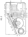
- a sample supplying device has a turntable 1 on which many sample cups are arranged.
- a reagent positioning device has a turntable 3 on which reagent bottles corresponding to plural analytical items are arranged.
- a transfer device has a fixed rail 38, a rail 37 movable on the rail 38, and a movable gripper 10 moving on the rail 37.
- a pipetting device has a movable member 13 and a pipetting nozzle 29 supported by the movable member 13.
- An incubator unit 9 heats a plurality of reaction vessels containing mixtures of a sample and a reagent at a certain temperature, for example 37°C.
- a measuring unit 46 has a flow cell and an optical system for measuring a reaction liquid in the flow cell.
- a tube 49 for sucking the reaction liquid is suspended from a movable arm 14.
- a reaction liquid sucked by the sucking operation of a syringe mechanism 48 through a tube 49 is introduced into the flow cell of the measuring unit 46 to be measured.
- the reaction liquid after measured is collected in a waste tank 20.
- a control unit 47 controls operation of each mechanism in the analyzing apparatus.
- the turntable 1 there are arranged many sample cups 2 containing biological samples such as blood or urine.
- the turntable 1 is intermittently rotated to position each of the sample cups 2 at a sucking position 27.
- On the turntable 3 there are arranged many reagent bottles 4.
- the reagent bottle 4 has three rooms 21, 22, 23.
- the reagent bottle 4 is placed so that a first reagent room 21 comes in the inner peripheral side. Therefore, when all the reagent bottles are set, three concentric circles are formed around the center of the rotation.
- a row of the first reagent rooms 21 is formed along the innermost concentric circle
- a row of the second reagent rooms 22 is formed along the intermediate concentric circle
- a row of the third reagent rooms 23 is formed along the outermost concentric circle.
- Three tip racks 5 are mounted on a rack supplying area in the moving region of the gripper 10. Beside the three tip rack 5, three vessel racks 7 are mounted. In each of the tip racks 5, tip insertion holes spacing in an equal interval are formed in the X-direction and in the Y-direction.
- a nozzle tip 6 has a nearly conical thin tube with a jaw 52 held by the gripper 10 as shown in FIG.4.
- the nozzle tip 6 is formed of a resin such as polypropylene.
- the tip rack 5 is a thin molded plastics and has legs 51.
- the tip rack 5 is formed of a resin such as polypropylene. Many unused nozzle tips 6 are mounted on the tip rack 5.
- the structure of the vessel rack 7 is the same as that of the tip rack 5.
- the reaction vessel 8 is a molded plastics with a jaw 53 held by the gripper 10 as shown in FIG.4.
- the incubator 9 in FIG.2 has a thermal-conductive metal member and a heating unit for heating the metal member at a given temperature.
- a thermal-conductive metal member In the metal member, there are formed a plurality of holes into which the reaction vessels are inserted. These holes are open upward.
- a transfer device for selectively transferring the nozzle tip and the reaction vessel has the rail 38 extending in the Y-direction.
- a base 50 having the rail 37 extending in the X-direction is connected to a belt 44 and moved on the rail 38 in one direction or the opposite direction with the belt 44 rotated by a motor 41 controlled by the control unit 47.
- the base 50 has a motor 40 for rotating a belt 43.
- a base 55 is slidably attached to the rail 37 on the base 50.
- the base 55 is connected to a belt 43 and moved on the rail 37 in the longitudinal direction of the rail 37 by rotation of the motor 40.
- the base 55 has a motor 42 for rotating a belt 45 and a vertical rail 39.
- the movable gripper 10 is slidably attached to a vertical rail 39, and moved upward and downward according to Morton of the belt 45.
- the movable gripper 10 has a pair of reclosable claws 57 capable of gripping either the nozzle tip 6 or the reaction vessel 8. The operation of releasing and gripping of the pair of claws 57 is controlled by the control unit 47.
- the movable gripper 10 grips up the unused tip 6 on the tip rack 5 one-by-one using the claws 57 to transfer it to a tip holder 60, and releases gripping of the tip 6 after inserting the tip 6 into a hole of the tip connecting station 11 in the holder 60. Further, the movable gripper 10 grips up the unused vessel 8 on the vessel rack 7 one-by-one using the claws 57 to transfer it to a tip holder 60, and releases gripping of the vessel 8 after inserting the vessel 8 into a hole of the sample receiving station 12 in the holder 60. These operations are repeated every interval of a given period.
- the sample receiving station 12, the tip connecting station 11 and the tip detaching station 18 on the tip holder 60 are linearly arranged along the horizontal moving locus 34 of the nozzle 29 of the pipetting device.
- the tip cleaning position 17, the reagent sucking positions 24, 25, 26 and the sample sucking position 27 are arranged along the horizontal moving locus 34 of the nozzle 29.
- the locus 34 passes through an area off from the rotating center of the turntable for reagents and linearly passes across the three concentric circles.
- the tip holder 60 receiving the tip 6 and the vessel 8 from the movable gripper 10 is installed in an area overlapped with the movable region of the movable gripper 10 and the movable region of the nozzle 29 of the movable member 13.
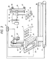
- the movable member 13 of the pipetting device is, as shown in FIG.3, connected to a belt 32 rotated between a pair of pulleys driven by a motor 33 to travel upward and downward according to motion of the belt.
- the nozzle 29 supported to the movable member 13 is connected to a syringe pump 62 through a conduit 61.
- the pump 62 is connected to a cleaning tank 64 through a switching valve 63.
- a slider 65 having the movable member 13 and the motor 33 is horizontally moved along a pair of rails 66, 67. As shown in FIG.2, the slider 65 is connected to a belt 30 and horizontally moved by rotation of the belt 30 driven by a motor 31.
- the motor 33 is started to drive based on a command of the control unit 47 to move the movable member 13 downward.
- the end of the nozzle 29 moved down is inserted into the tip 6.
- the outer wall of the nozzle 29 is tightly connected to the inner wall of the tip 6. Therefore, the pushing force from the nozzle 29 is applied to the tip holder 60.
- the tip holder 60 is made of a material endurable against such a pushing force, for example, stainless steel plate of 8 mm thickness.
- the tip 6 connected to the nozzle 29 is also moved upward together.
- the tip delivers the reagents from the reagent bottles 24, 25 and 26 and the sample from the sample cup 2 to the reaction vessel 8
- the tip 6 finishing its role is transferred to the tip detaching station 18 of the tip holder 60.
- the tip 6 is moved downward and in the lateral direction so that the upper portion of the jaw 52 of the tip 6 touches to the lower portion of the station 18 by motion of the nozzle 29.
- the nozzle 29 is moved upward to hook the upper portion of the tip to the tip holder 60 and the tip 6 is detached from the nozzle 29.
- a box 15 for receiving waste having a size extending over the vessel rack supplying area and the tip holder 60 is placed below.
- a collecting bag made of vinyl chloride is set inside the box 15.
- the used tip 6 detached at the tip detaching station 18 is dropped and collected in the bag.
- the used reaction vessel 8 after sucked the reaction liquid at the reaction liquid sucking position 28 is gripped by the movable gripper 10 and transferred from the sucking position 28 to the throwing-out hole 19. Then the gripper 10 is released on the hole 19 to drop the used vessel 8 into the box 15.
- all that an operator has to do is to exchange the bags. Therefore, the operator can manage with touching neither the used tips 6 nor the used vessels 8.
- the sucking tube 49 supported by the movable arm 14 is moved both horizontally and vertically.
- the tube 49 is lowered into the reaction vessel 8 placed at the sucking position 28, and the reaction liquid is conducted to the flow cell of the measuring unit 46 by operation of the syringe mechanism 48.
- the tube 49 is moved upward and transferred onto a cleaning solution bottle 36.
- the tube 49 is moved downward and a buffer solution is conducted to the flow cell through the tube 49.
- the tube 49 is moved upward and transferred to the sucking position 28 for the next reaction liquid.
- the various kinds of solutions passed through the measuring unit 46 are collected into the waste liquid tank 20.
- the nozzle tips 6 are supplied by a vendor in a state of being arranged in the tip rack 5.
- the unused reaction vessels 8 are also supplied by a vendor in a state of being arranged in the vessel rack 7.
- An operator mounts such a tip rack 5 and such a vessel rack 7 on the tip supplying area.
- the sample cups 2 containing samples to be analyzed are arranged on the turntable 1, and reagent bottles 4 corresponding to analytical items are arranged on the turntable 3.
- the movable gripper 10 is moved onto the tip rack 5 and moved down with the claws 57 kept open to grip one of nozzle tips 6 at the jaw 52 by closing operation of the claws 57.
- the gripper 10 is moved upward in keeping the state as it is and then is horizontally moved to transfer the nozzle tip 6 to the tip holder 60.
- the tip 6 is placed at the tip connecting station 11 by the gripper 10 and released from the gripper 10 by opening operation of the claws 57.
- the nozzle 29 is moved down to the tip connection station 11, and the nozzle 29 is connected to the tip 6 by pushing the tip 6 with the nozzle 29.
- the nozzle 29 is moved upward and the tip 6 connected to the nozzle 29 is horizontally moved toward the sucking position 24 on the turntable 3. During that time, the movable gripper 10 is moved onto the vessel rack 7 and grips one of the vessels 8 at the jaw 53 of the vessel 8 to place it to the sample receiving station 12 of the tip holder 60.
- a given amount of the first reagent is sucked with sucking operation of the pump 62 into the tip 6 which is moved down into the first reagent room 21 positioned at the sucking position 24.
- the tip 6 having the first reagent is moved upward and horizontally moved to the sample receiving station 12.
- the reagent is delivered from the tip 6 moved down to the station 12 into the vessel 8.
- Then the tip 6 is moved upward to transferred to the cleaning tank 17.
- the cleaning tank 17 is supplied with cleaning solution from the cleaning unit 16.
- the tip 6 is cleaned in the cleaning tank 17.
- the turntable 3 is rotated to position the second reagent room 22 on the intermediate concentric circle to the sucking position 25.
- the cleaned tip 6 is inserted into the reagent room 25 of the sucking position 25 to suck a given amount of the second reagent.
- the upward moved tip 6 is transferred to the sample receiving station 12 to deliver the second reagent into the vessel 8.
- the tip 6 is cleaned in the cleaning tank 17.
- the turntable 3 moves the third reagent room 23 in the outermost circle to the sucking position 26.
- the third reagent sucked in the tip 6 is delivered into the vessel 8 on the station 12.
- the nozzle tip 6 having delivered the reagent is again cleaned in the cleaning tank 17.
- the cleaned tip 6 is moved to the sucking position 27 of the turntable 1, and moved down into the sample cup 2 positioned at position 27. A given amount of the sample is sucked into the tip 6 by operation of the pump 62.
- the tip 6 is upward and horizontally moved, and moved downward at the sample receiving station 12 of the tip holder 60 to deliver the sample in the tip 6 into the reaction vessel 8 already containing the reagents.
- the tip 8 after finishing delivery of the reagent and the sample is transferred to the detaching station 18 to be detached from the nozzle 29.
- the reaction vessel 8 containing the mixture of the sample and reagent is gripped by the movable gripper 10 at the jaw 53 to be inserted into a vacant receiving hole in the incubator 9 and released from the gripper 10.
- the vessel 8 is incubated at a constant temperature for a given time period determined depending on the analytical item. In the incubator 9, reactions of plural samples are proceeded in parallel.
- the reaction vessel 8 passed the given reaction time is lifted by the gripper 10 to be set in the sucking position 28.
- the reaction liquid sucked from the tube 49 is conducted to the flow cell of the measuring unit 46.
- the vacant vessel 8 is gripped by the gripper 10 at the sucking position 28 and transferred to the throwing-out hole 19 to be thrown out.
- the transfer device transfers a disposable tip 6 and a vessel 8 for the next sample to the tip holder 60, and the pipetting device performs pipetting operation of the reagent and the sample.
- the pipetting device performs pipetting operation of the reagent and the sample.
- the tip rack can be formed of a material as comparatively low a strength as the tip rack can support many tips spacing one another. Since such a tip rack is supplied by vendor in a state where many tips are orderly arranged, it is unnecessary for an operator to arrange the tips in the tip rack.
Landscapes
- Engineering & Computer Science (AREA)
- Robotics (AREA)
- Physics & Mathematics (AREA)
- Health & Medical Sciences (AREA)
- Life Sciences & Earth Sciences (AREA)
- Chemical & Material Sciences (AREA)
- Analytical Chemistry (AREA)
- Biochemistry (AREA)
- General Health & Medical Sciences (AREA)
- General Physics & Mathematics (AREA)
- Immunology (AREA)
- Pathology (AREA)
- Automatic Analysis And Handling Materials Therefor (AREA)
Applications Claiming Priority (3)
| Application Number | Priority Date | Filing Date | Title |
|---|---|---|---|
| JP22622694 | 1994-09-21 | ||
| JP226226/94 | 1994-09-21 | ||
| JP22622694 | 1994-09-21 |
Publications (2)
| Publication Number | Publication Date |
|---|---|
| EP0703455A1 true EP0703455A1 (fr) | 1996-03-27 |
| EP0703455B1 EP0703455B1 (fr) | 2001-12-05 |
Family
ID=16841875
Family Applications (1)
| Application Number | Title | Priority Date | Filing Date |
|---|---|---|---|
| EP95114811A Expired - Lifetime EP0703455B1 (fr) | 1994-09-21 | 1995-09-20 | Appareil d'analyse avec dispositif de pipettage |
Country Status (3)
| Country | Link |
|---|---|
| US (1) | US5639425A (fr) |
| EP (1) | EP0703455B1 (fr) |
| DE (1) | DE69524338T2 (fr) |
Cited By (9)
| Publication number | Priority date | Publication date | Assignee | Title |
|---|---|---|---|---|
| US6293750B1 (en) | 1998-07-14 | 2001-09-25 | Bayer Corporation | Robotics for transporting containers and objects within an automated analytical instrument and service tool for servicing robotics |
| US6426047B1 (en) | 1999-02-01 | 2002-07-30 | Matrix Technologies Corporations | Disposable tip magazine |
| EP1231472A1 (fr) * | 2001-02-10 | 2002-08-14 | Molecular Devices Corporation | Système intégré de distribution de fluide et d'analyse |
| EP0977039A3 (fr) * | 1998-07-27 | 2004-04-14 | Hitachi, Ltd. | Methode de manipulation d' echantillons corporels et appareil d'analyse |
| DE102004002709A1 (de) * | 2004-01-19 | 2005-08-11 | Christian Daschner | Verfahren und Vorrichtung zur Aufbringung einer Flüssigkeit auf eine Zielstruktur |
| DE102004057450A1 (de) * | 2004-11-24 | 2006-06-01 | Cybio Ag | Automatisches Pipetier- und Analysegerät |
| US7939031B2 (en) * | 2004-07-16 | 2011-05-10 | Stemcell Technologies, Inc. | Automated pipette machine |
| CN103026238A (zh) * | 2010-07-28 | 2013-04-03 | 株式会社日立高新技术 | 核酸分析装置 |
| CN108516340A (zh) * | 2018-04-16 | 2018-09-11 | 苏州阡晨金属包装设备有限公司 | 一种易拉罐输送搬运机构 |
Families Citing this family (31)
| Publication number | Priority date | Publication date | Assignee | Title |
|---|---|---|---|---|
| JP3582240B2 (ja) * | 1996-06-14 | 2004-10-27 | 東ソー株式会社 | 自動検体前処理装置および自動検体前処理方法 |
| KR20010012479A (ko) | 1997-05-02 | 2001-02-15 | 다니엘 엘. 캐시앙, 헨리 엘. 노르호프, 피터 알. 쉬어리 | 반응 리셉터클 장치 |
| JP3062481B2 (ja) * | 1997-11-19 | 2000-07-10 | グルポ グリフォルス,エス.エー. | 実験室試験を自動的に行う装置 |
| DE29720432U1 (de) * | 1997-11-19 | 1999-03-25 | Heimberg, Wolfgang, Dr., 85560 Ebersberg | Roboter |
| US6006800A (en) * | 1997-11-21 | 1999-12-28 | Nichiryo Co., Ltd. | Apparatus and method for automatic distribution |
| ES2286750T3 (es) * | 1998-05-01 | 2007-12-01 | Gen-Probe Incorporated | Dispositivo para agitar el contenido liquido de un contenedor. |
| US8337753B2 (en) | 1998-05-01 | 2012-12-25 | Gen-Probe Incorporated | Temperature-controlled incubator having a receptacle mixing mechanism |
| JP3670503B2 (ja) * | 1999-01-12 | 2005-07-13 | 株式会社日立製作所 | 分注装置 |
| AU2633100A (en) * | 1999-01-29 | 2000-08-18 | Genomic Instrumentation Services, Inc. | Robotic work station |
| DE60029356T2 (de) * | 2000-03-15 | 2007-02-15 | Hitachi, Ltd. | Automatischer analysator und für ihn genutzte teilenachschubvorrichtung |
| US7220590B2 (en) * | 2001-03-14 | 2007-05-22 | Beckman Coulter, Inc. | Conductive plastic rack for pipette tips |
| US6825041B2 (en) * | 2001-03-16 | 2004-11-30 | Beckman Coulter, Inc. | Method and system for automated immunochemistry analysis |
| JP2004535572A (ja) * | 2001-06-13 | 2004-11-25 | ケニス エフ. ウーヘンハイマー, | 自動化流体操作システムおよび方法 |
| US20030003591A1 (en) * | 2001-07-02 | 2003-01-02 | Ortho-Clinical Diagnostics, Inc. | Reaction vessel |
| US7312084B2 (en) * | 2001-07-13 | 2007-12-25 | Ortho-Clinical Diagnostics, Inc. | Tandem incubator for clinical analyzer |
| ATE355529T1 (de) * | 2003-08-20 | 2006-03-15 | Sysmex Corp | Probenanalysegerät und eine vorrichtung zur detektion von nukleinsäuren |
| US7501094B2 (en) * | 2003-09-15 | 2009-03-10 | Syngenta Limited | Preparation and characterization of formulations in a high throughput mode |
| US7396512B2 (en) | 2003-11-04 | 2008-07-08 | Drummond Scientific Company | Automatic precision non-contact open-loop fluid dispensing |
| US7964413B2 (en) | 2005-03-10 | 2011-06-21 | Gen-Probe Incorporated | Method for continuous mode processing of multiple reaction receptacles in a real-time amplification assay |
| JP4910516B2 (ja) * | 2006-07-04 | 2012-04-04 | 富士通株式会社 | マイクロインジェクション装置 |
| US20090004063A1 (en) * | 2007-06-29 | 2009-01-01 | Symyx Technologies, Inc. | Apparatus and method for actuating a syringe |
| US9046507B2 (en) | 2010-07-29 | 2015-06-02 | Gen-Probe Incorporated | Method, system and apparatus for incorporating capacitive proximity sensing in an automated fluid transfer procedure |
| AU2012222178B2 (en) | 2011-02-24 | 2014-12-18 | Gen-Probe Incorporated | Systems and methods for distinguishing optical signals of different modulation frequencies in an optical signal detector |
| EP2546655B1 (fr) * | 2011-07-13 | 2019-12-04 | F. Hoffmann-La Roche AG | Instrument et procédé de traitement automatique d'échantillons liquides |
| TWI513811B (zh) * | 2011-10-27 | 2015-12-21 | Hon Hai Prec Ind Co Ltd | 自動解蠟裝置 |
| CN109358202B (zh) | 2013-03-15 | 2023-04-07 | 雅培制药有限公司 | 具有竖直布置的圆盘传送带的自动化诊断分析仪及相关方法 |
| EP3964839B1 (fr) | 2013-03-15 | 2024-04-10 | Abbott Laboratories | Analyseurs diagnostiques automatiques comprenant des systèmes de rail accessibles par l'arrière et procédés associés |
| CN105190317B (zh) | 2013-03-15 | 2018-05-04 | 雅培制药有限公司 | 具有预处理转盘的诊断分析机及相关方法 |
| CN103336138B (zh) * | 2013-06-13 | 2015-04-08 | 长春迪瑞医疗科技股份有限公司 | 一种用于全自动化学发光免疫分析仪的自动加载装置 |
| US11415588B2 (en) | 2017-12-05 | 2022-08-16 | Siemens Healthcare Diagnostics Inc. | Probe tip waste chutes and methods thereof for automated diagnostic analysis apparatus |
| US20250135450A1 (en) * | 2023-10-26 | 2025-05-01 | Revvity Health Sciences, Inc. | Lab tools and laboratory liquid handling systems and methods including same |
Citations (9)
| Publication number | Priority date | Publication date | Assignee | Title |
|---|---|---|---|---|
| US4087248A (en) * | 1976-07-26 | 1978-05-02 | Miles Laughton E | Multiple assay machine and method |
| JPS59188538A (ja) * | 1983-04-08 | 1984-10-25 | Japan Spectroscopic Co | 自動分注装置 |
| DE3733098A1 (de) * | 1986-10-01 | 1988-04-14 | Hitachi Ltd | Enzymimmunoassay und automatisches analysengeraet zu dessen durchfuehrung |
| EP0282076A2 (fr) * | 1987-03-11 | 1988-09-14 | Sumitomo Electric Industries Limited | Appareil distributeur |
| JPH04296655A (ja) | 1991-03-26 | 1992-10-21 | Mochida Pharmaceut Co Ltd | 液体の計量方法およびこれを用いた自動分注方法およびその装置 |
| EP0557828A1 (fr) * | 1992-02-22 | 1993-09-01 | Horiba, Ltd. | Dispositif de prétraitement pour analyses |
| JPH0688828A (ja) | 1992-09-08 | 1994-03-29 | Olympus Optical Co Ltd | 免疫自動分析装置 |
| JPH0627743B2 (ja) | 1985-03-25 | 1994-04-13 | 株式会社日立製作所 | 自動分析装置 |
| DE4306332A1 (de) * | 1993-02-24 | 1994-08-25 | Mannesmann Ag | Vorrichtung zum Wechseln von Meß- und/oder Probensonden |
Family Cites Families (13)
| Publication number | Priority date | Publication date | Assignee | Title |
|---|---|---|---|---|
| JPS55140156A (en) * | 1979-04-19 | 1980-11-01 | Olympus Optical Co Ltd | Distribution method |
| US4287155A (en) * | 1980-06-16 | 1981-09-01 | Eastman Kodak Company | Sample tray and carrier for chemical analyzer |
| US5104621A (en) * | 1986-03-26 | 1992-04-14 | Beckman Instruments, Inc. | Automated multi-purpose analytical chemistry processing center and laboratory work station |
| US4824641A (en) * | 1986-06-20 | 1989-04-25 | Cetus Corporation | Carousel and tip |
| JPH0754326B2 (ja) * | 1986-06-24 | 1995-06-07 | 株式会社東芝 | 自動化学分析装置 |
| CA1321940C (fr) * | 1987-05-02 | 1993-09-07 | Teruaki Itoh | Distributeur d'echantillons liquides |
| US5008082A (en) * | 1988-08-25 | 1991-04-16 | Eastman Kodak Company | Analyzers using linear sample trays with random access |
| US4927545A (en) * | 1988-10-06 | 1990-05-22 | Medical Automation Specialties, Inc. | Method and apparatus for automatic processing and analyzing of blood serum |
| JP2626738B2 (ja) * | 1990-03-13 | 1997-07-02 | 三共株式会社 | 化学発光検出装置 |
| US5200151A (en) * | 1990-05-21 | 1993-04-06 | P B Diagnostic Systems, Inc. | Fluid dispensing system having a pipette assembly with preset tip locator |
| US5213764A (en) * | 1991-05-15 | 1993-05-25 | Miles Inc. | Metering device for slide analysis system |
| US5190727A (en) * | 1991-07-18 | 1993-03-02 | Eastman Kodak Company | Device for moving and positioning pipette trays in an analyzer |
| JPH0627743A (ja) * | 1992-07-09 | 1994-02-04 | Mita Ind Co Ltd | 電子写真用キャリヤ |
-
1995
- 1995-09-18 US US08/529,802 patent/US5639425A/en not_active Expired - Lifetime
- 1995-09-20 EP EP95114811A patent/EP0703455B1/fr not_active Expired - Lifetime
- 1995-09-20 DE DE69524338T patent/DE69524338T2/de not_active Expired - Lifetime
Patent Citations (9)
| Publication number | Priority date | Publication date | Assignee | Title |
|---|---|---|---|---|
| US4087248A (en) * | 1976-07-26 | 1978-05-02 | Miles Laughton E | Multiple assay machine and method |
| JPS59188538A (ja) * | 1983-04-08 | 1984-10-25 | Japan Spectroscopic Co | 自動分注装置 |
| JPH0627743B2 (ja) | 1985-03-25 | 1994-04-13 | 株式会社日立製作所 | 自動分析装置 |
| DE3733098A1 (de) * | 1986-10-01 | 1988-04-14 | Hitachi Ltd | Enzymimmunoassay und automatisches analysengeraet zu dessen durchfuehrung |
| EP0282076A2 (fr) * | 1987-03-11 | 1988-09-14 | Sumitomo Electric Industries Limited | Appareil distributeur |
| JPH04296655A (ja) | 1991-03-26 | 1992-10-21 | Mochida Pharmaceut Co Ltd | 液体の計量方法およびこれを用いた自動分注方法およびその装置 |
| EP0557828A1 (fr) * | 1992-02-22 | 1993-09-01 | Horiba, Ltd. | Dispositif de prétraitement pour analyses |
| JPH0688828A (ja) | 1992-09-08 | 1994-03-29 | Olympus Optical Co Ltd | 免疫自動分析装置 |
| DE4306332A1 (de) * | 1993-02-24 | 1994-08-25 | Mannesmann Ag | Vorrichtung zum Wechseln von Meß- und/oder Probensonden |
Non-Patent Citations (1)
| Title |
|---|
| PATENT ABSTRACTS OF JAPAN vol. 9, no. 50 (P - 339) 5 March 1985 (1985-03-05) * |
Cited By (17)
| Publication number | Priority date | Publication date | Assignee | Title |
|---|---|---|---|---|
| US6332636B1 (en) | 1998-07-14 | 2001-12-25 | Bayer Corporation | Robotics for transporting containers and objects within an automated analytical instrument and service tool for servicing robotics |
| US6374982B1 (en) | 1998-07-14 | 2002-04-23 | Bayer Corporation | Robotics for transporting containers and objects within an automated analytical instrument and service tool for servicing robotics |
| US6293750B1 (en) | 1998-07-14 | 2001-09-25 | Bayer Corporation | Robotics for transporting containers and objects within an automated analytical instrument and service tool for servicing robotics |
| US7105351B2 (en) | 1998-07-27 | 2006-09-12 | Hitachi, Ltd. | Handling method of body fluid sample and analysis apparatus using the same |
| EP0977039A3 (fr) * | 1998-07-27 | 2004-04-14 | Hitachi, Ltd. | Methode de manipulation d' echantillons corporels et appareil d'analyse |
| US6924152B2 (en) | 1998-07-27 | 2005-08-02 | Hitachi, Ltd. | Handling method of body fluid sample and analysis apparatus using the same |
| EP1876451A3 (fr) * | 1998-07-27 | 2012-02-29 | Hitachi, Ltd. | Procédé et système pour fournir des informations visuelles d'un emplacement à distance pour un conducteur de véhicule |
| US6426047B1 (en) | 1999-02-01 | 2002-07-30 | Matrix Technologies Corporations | Disposable tip magazine |
| EP1231472A1 (fr) * | 2001-02-10 | 2002-08-14 | Molecular Devices Corporation | Système intégré de distribution de fluide et d'analyse |
| DE102004002709A1 (de) * | 2004-01-19 | 2005-08-11 | Christian Daschner | Verfahren und Vorrichtung zur Aufbringung einer Flüssigkeit auf eine Zielstruktur |
| US7939031B2 (en) * | 2004-07-16 | 2011-05-10 | Stemcell Technologies, Inc. | Automated pipette machine |
| DE102004057450A1 (de) * | 2004-11-24 | 2006-06-01 | Cybio Ag | Automatisches Pipetier- und Analysegerät |
| US7541001B2 (en) | 2004-11-24 | 2009-06-02 | Cybio Ag | Automatic pipetting and analyzing device |
| DE102004057450B4 (de) * | 2004-11-24 | 2013-07-25 | Cybio Ag | Automatisches Pipetier- und Analysegerät |
| CN103026238A (zh) * | 2010-07-28 | 2013-04-03 | 株式会社日立高新技术 | 核酸分析装置 |
| CN103026238B (zh) * | 2010-07-28 | 2015-11-25 | 株式会社日立高新技术 | 核酸分析装置 |
| CN108516340A (zh) * | 2018-04-16 | 2018-09-11 | 苏州阡晨金属包装设备有限公司 | 一种易拉罐输送搬运机构 |
Also Published As
| Publication number | Publication date |
|---|---|
| EP0703455B1 (fr) | 2001-12-05 |
| DE69524338T2 (de) | 2002-08-08 |
| DE69524338D1 (de) | 2002-01-17 |
| US5639425A (en) | 1997-06-17 |
Similar Documents
| Publication | Publication Date | Title |
|---|---|---|
| US5639425A (en) | Analyzing apparatus having pipetting device | |
| EP1256808B1 (fr) | Systeme de transfert et de traitement de receptacles | |
| US11524287B2 (en) | Automatic pipetting device for transferring samples and/or reagents and method for transferring liquid samples and/or reagents | |
| EP1546737B1 (fr) | Robot a deux axes pour transfert d'echantillons | |
| JP4232982B2 (ja) | 試料の自動臨床分析装置 | |
| EP0888554A1 (fr) | Preparation d'echantillons | |
| JPH0267962A (ja) | 生物流体検定装置 | |
| US20030031542A1 (en) | Appatatus and method for handling pipetting tip magazines | |
| US4413060A (en) | Process and apparatus for distribution and preparation of samples from primary vessels | |
| CA2737955A1 (fr) | Analyseur automatise pour diagnostics et procede correspondant | |
| JP2005507078A (ja) | 規定された体積の固体粒子の並行分配のための方法および装置 | |
| WO1994014074A1 (fr) | Procede et dispositif automatise pour la realisation de tests immunologiques | |
| JP2000121647A (ja) | 自動分注装置 | |
| JP3267117B2 (ja) | 分注装置を備えた分析装置 | |
| CN108176336B (zh) | 一种高通量共沉淀合成装置 | |
| CN220625913U (zh) | 一种自动化全血血样制备仪 | |
| CN117169537B (zh) | 一种试样分配装置及样本分析系统 | |
| CN117607474A (zh) | 一种全自动分杯系统 | |
| JP3778002B2 (ja) | 分注装置 | |
| CN118922523A (zh) | 生物芯片的自动化控制系统及其自动化控制方法 | |
| JP4039002B2 (ja) | 検体洗浄装置 | |
| EP1187680A1 (fr) | Appareil de lavage universel pour plaque de microtitrage et autres elements similaires | |
| AU705813B2 (en) | Specimen preparation | |
| CN223674617U (zh) | 提取件 | |
| JP3820912B2 (ja) | 液体のシェイキング装置 |
Legal Events
| Date | Code | Title | Description |
|---|---|---|---|
| PUAI | Public reference made under article 153(3) epc to a published international application that has entered the european phase |
Free format text: ORIGINAL CODE: 0009012 |
|
| 17P | Request for examination filed |
Effective date: 19950920 |
|
| AK | Designated contracting states |
Kind code of ref document: A1 Designated state(s): DE FR GB |
|
| 17Q | First examination report despatched |
Effective date: 19990521 |
|
| GRAG | Despatch of communication of intention to grant |
Free format text: ORIGINAL CODE: EPIDOS AGRA |
|
| GRAG | Despatch of communication of intention to grant |
Free format text: ORIGINAL CODE: EPIDOS AGRA |
|
| GRAH | Despatch of communication of intention to grant a patent |
Free format text: ORIGINAL CODE: EPIDOS IGRA |
|
| GRAH | Despatch of communication of intention to grant a patent |
Free format text: ORIGINAL CODE: EPIDOS IGRA |
|
| GRAA | (expected) grant |
Free format text: ORIGINAL CODE: 0009210 |
|
| AK | Designated contracting states |
Kind code of ref document: B1 Designated state(s): DE FR GB |
|
| REG | Reference to a national code |
Ref country code: GB Ref legal event code: IF02 |
|
| REF | Corresponds to: |
Ref document number: 69524338 Country of ref document: DE Date of ref document: 20020117 |
|
| PLBE | No opposition filed within time limit |
Free format text: ORIGINAL CODE: 0009261 |
|
| STAA | Information on the status of an ep patent application or granted ep patent |
Free format text: STATUS: NO OPPOSITION FILED WITHIN TIME LIMIT |
|
| 26N | No opposition filed | ||
| PGFP | Annual fee paid to national office [announced via postgrant information from national office to epo] |
Ref country code: DE Payment date: 20140917 Year of fee payment: 20 |
|
| PGFP | Annual fee paid to national office [announced via postgrant information from national office to epo] |
Ref country code: GB Payment date: 20140917 Year of fee payment: 20 |
|
| PGFP | Annual fee paid to national office [announced via postgrant information from national office to epo] |
Ref country code: FR Payment date: 20140906 Year of fee payment: 20 |
|
| REG | Reference to a national code |
Ref country code: DE Ref legal event code: R071 Ref document number: 69524338 Country of ref document: DE |
|
| REG | Reference to a national code |
Ref country code: GB Ref legal event code: PE20 Expiry date: 20150919 |
|
| PG25 | Lapsed in a contracting state [announced via postgrant information from national office to epo] |
Ref country code: GB Free format text: LAPSE BECAUSE OF EXPIRATION OF PROTECTION Effective date: 20150919 |