EP0703464B1 - Polarimetrisches Radarverfahren und polarimetrische Radaranordnung - Google Patents
Polarimetrisches Radarverfahren und polarimetrische Radaranordnung Download PDFInfo
- Publication number
- EP0703464B1 EP0703464B1 EP95114457A EP95114457A EP0703464B1 EP 0703464 B1 EP0703464 B1 EP 0703464B1 EP 95114457 A EP95114457 A EP 95114457A EP 95114457 A EP95114457 A EP 95114457A EP 0703464 B1 EP0703464 B1 EP 0703464B1
- Authority
- EP
- European Patent Office
- Prior art keywords
- frequency
- emitted
- signal
- waves
- multiplexer
- Prior art date
- Legal status (The legal status is an assumption and is not a legal conclusion. Google has not performed a legal analysis and makes no representation as to the accuracy of the status listed.)
- Expired - Lifetime
Links
- 238000000034 method Methods 0.000 title claims description 13
- 239000011159 matrix material Substances 0.000 claims description 13
- 230000010287 polarization Effects 0.000 description 30
- 230000005540 biological transmission Effects 0.000 description 10
- 239000013598 vector Substances 0.000 description 10
- 238000012937 correction Methods 0.000 description 6
- 230000001419 dependent effect Effects 0.000 description 3
- 239000000758 substrate Substances 0.000 description 3
- 239000004065 semiconductor Substances 0.000 description 2
- 238000000926 separation method Methods 0.000 description 2
- 238000006243 chemical reaction Methods 0.000 description 1
- 238000011161 development Methods 0.000 description 1
- 230000018109 developmental process Effects 0.000 description 1
- 238000011156 evaluation Methods 0.000 description 1
- 238000011835 investigation Methods 0.000 description 1
- 238000012545 processing Methods 0.000 description 1
- 230000003252 repetitive effect Effects 0.000 description 1
- 230000001629 suppression Effects 0.000 description 1
Images
Classifications
-
- H—ELECTRICITY
- H01—ELECTRIC ELEMENTS
- H01Q—ANTENNAS, i.e. RADIO AERIALS
- H01Q21/00—Antenna arrays or systems
- H01Q21/24—Combinations of antenna units polarised in different directions for transmitting or receiving circularly and elliptically polarised waves or waves linearly polarised in any direction
- H01Q21/245—Combinations of antenna units polarised in different directions for transmitting or receiving circularly and elliptically polarised waves or waves linearly polarised in any direction provided with means for varying the polarisation
-
- G—PHYSICS
- G01—MEASURING; TESTING
- G01S—RADIO DIRECTION-FINDING; RADIO NAVIGATION; DETERMINING DISTANCE OR VELOCITY BY USE OF RADIO WAVES; LOCATING OR PRESENCE-DETECTING BY USE OF THE REFLECTION OR RERADIATION OF RADIO WAVES; ANALOGOUS ARRANGEMENTS USING OTHER WAVES
- G01S7/00—Details of systems according to groups G01S13/00, G01S15/00, G01S17/00
- G01S7/02—Details of systems according to groups G01S13/00, G01S15/00, G01S17/00 of systems according to group G01S13/00
- G01S7/024—Details of systems according to groups G01S13/00, G01S15/00, G01S17/00 of systems according to group G01S13/00 using polarisation effects
Definitions
- the invention relates to a polarimetric radar method and a polarimetric radar arrangement.
- Enable polarimetric radar methods and arrangements compared to the non-polarimetric case additional Interference suppression measures and improved target discovery as well as by determining characteristic polarization-dependent ones Scattering properties of a target Target classification and / or target separation in Multiple target situations.
- the scatter characteristic is in generally a 2x2 scattering matrix determined by orthogonal Polarizations are transmitted and transmitted in orthogonal signals Polarizations Receive signals are recorded and evaluated. This requires at least with regard to the transmission signals time-sequential procedure, resulting in a relative movement between radar arrangement and target the received signals a Doppler component overlaid by determining the Relative speed through a correction calculation again can be compensated.
- the correction calculation using the relative speed is unfavorable, among other things because of the time required for the investigation of a speed value and its only moderate accuracy.
- the object of the present invention is a method and to specify a suitable device which allows determine the scattering matrix of a reflection body, without a Doppler component superimposed on the reflection signal to have to compensate by an additional correction calculation.
- the invention is based on exemplary embodiments referring to the figure in more detail illustrated.
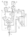
- Two antenna elements EV and EH form a transmit-receive antenna.
- the antenna elements are for orthogonal Polarizations designed, for example EH for horizontal (H) and EV for vertical (V) polarization.
- the antenna elements are optional using the SU transmit / receive switch for transmission with a dining network SP or a receiving mixer arrangement EM connectable.
- the dining network is advantageously designed so that with only a few switchable elements and signal paths three different Send polarizations are adjustable.
- the feed network can contain a 1: 3 multiplexer M, the oscillator signal OS present on the input side forwards one of its three outputs.
- a branching element via the third output of the multiplexer TS preferably a 3dB power divider, whose two outputs to one of the two antenna elements EV, EH lead.
- 1 demultiplexers DM1, DM2 can be provided for decoupling the individual Signal paths in the feed network.
- ⁇ 90 °, so that by switching the Multiplexers M one horizontal, one vertical and one circular polarization can be set.
- the transmit-receive changeover switches SU When receiving, the transmit-receive changeover switches SU are in brought the position indicated by a broken line and those from the orthogonally polarized antenna elements Recorded antenna signals RH, RV are on the changeover switch SU separately fed two parallel reception channels.
- the Mixed signal is preferably via a coupler K from the the oscillator signal OS lead to the multiplexer M decoupled and via a 3dB divider TM to the distributed two converters MH, MV.
- the feed network, the switch and the converter with 3dB divider and coupler monolithic in integrated into a semiconductor substrate.
- the supply line to the The input of the multiplexer is then the only high frequency Interface leading to signals outside the Parts of the radar arrangement arranged on the substrate.
- the separate Receive channels to orthogonally polarized antenna elements deliver repetitive frequencies at the output of the converters MH, MV or intermediate frequency received signals ZH, ZV, which is preferably processed digitally after scanning become.
- the received signals deliver Information about the polarization dependent Scattering properties of a target. It is common to have two orthogonal ones Send polarizations each receive signals to determine in orthogonal polarizations.
- the complex The values of the received signals can be changed immediately after standardization as components one to describe the polarization dependent Scattering characteristic of a target in use Scatter matrix can be used if radar arrangement and target in both transmit polarizations in identical spatial allocation. In the real case, however, is one To assume relative movement between the radar arrangement and the target, so that a Doppler component overlaps, by a phase correction calculation with a known relative speed can be compensated.
- q ' S 21 + S 22 , q S 11 + S 12th , q with S mn as components of the scattering matrix.
- the structure of the scattering matrix can be completely determined by determining pairs of amplitude quotients (q i , q ' i ) for three different transmit polarizations.
- the phase correlation of signals in chronological succession Sections with different transmission polarization is no longer required. Are important the normalized amplitudes of the received signals, the relative Phase of the signals in the two receiving channels and the assignment to the respective transmission polarization.
- the choice of the three transmit polarizations is arbitrary in itself, however, the combination of two orthogonal polarizations is preferred with another, by equally weighted Combination of these two resulting polarizations.
- the reception signals are not evaluated in one with digital evaluation device shown outside of the semiconductor substrate.
- the radar arrangement preferably works as a pulse radar.
- the oscillator signal delivers the mixed signal to the reception phases for the converter, the conversion to an intermediate frequency position by switching the oscillator frequency from transmission phase to reception phase between one Transmission frequency and a mixer frequency takes place.
Landscapes
- Engineering & Computer Science (AREA)
- Computer Networks & Wireless Communication (AREA)
- Physics & Mathematics (AREA)
- General Physics & Mathematics (AREA)
- Radar, Positioning & Navigation (AREA)
- Remote Sensing (AREA)
- Radar Systems Or Details Thereof (AREA)
Description
Claims (5)
- Verfahren zur Ermittlung der Streumatrix eines Reflexionskörpers, bei welchem eine dem Reflexionssignal überlagerte Dopplerkomponente nicht durch eine zusätzliche Korrekturrechnung kompensiert werden muß,
dadurch gekennzeichnet,
daß der komplexe Amplitudenquotient des reflektierten Signals in Beziehung zum komplexen Amplitudenquotienten des ausgesandten Signals betrachtet wird, und daß aus der Betrachtung von drei solcher Beziehungen bezüglich drei ausgesandter, verschieden polarisierter Wellen die Parameter der Streumatrix bestimmt werden. - Verfahren nach Anspruch 1, dadurch gekennzeichnet, daß eine der drei ausgesandten, verschieden polarisierten Wellen durch die Überlagerung der zwei anderen zueinander orthogonal polarisierten Wellen generiert wird.
- Verfahren nach einem der Ansprüche 1 oder 2, dadurch gekennzeichnet, daß zur Generierung der Frequenz der ausgesandten Wellen und der Frequenz, mit welcher die reflektierten Signale heruntergemischt werden ein einzelner Oszillator in seiner Frequenz geschaltet wird.
- Vorrichtung zur Ermittlung der Streumatrix eines Reflexionskörpers, bei welchem eine dem Reflexionssignal überlagerte Dopplerkomponente nicht durch eine zusätzliche Korrekturrechnung kompensiert werden muß,
dadurch gekennzeichnet,
daß das Speisenetzwerk zum Aussenden von drei verschieden polarisierten Wellen einen 1:3-Mulitplexer, zwei 2:1-Demultiplexer und ein Verzweigungsglied in der Weise enthält, daß je ein Eingang der Demultiplexer unmittelbar mit je einem Ausgang des Multiplexers und der jeweils zweite Eingang der Demultiplexer mittelbar über das Verzweigungsglied mit dem übrigen Ausgang des Multiplexers verbunden ist. - Vorrichtung nach Anspruch 4, dadurch gekennzeichnet, daß zur Generierung der Frequenz der ausgesandten Wellen und der Frequenz, mit welcher die reflektierten Signale heruntergemischt werden ein einzelner, in seiner Frequenz schaltbarer Oszillator vorgesehen ist.
Applications Claiming Priority (2)
| Application Number | Priority Date | Filing Date | Title |
|---|---|---|---|
| DE4433789 | 1994-09-22 | ||
| DE4433789A DE4433789A1 (de) | 1994-09-22 | 1994-09-22 | Polarimetrisches Radarverfahren und polarimetrische Radaranordnung |
Publications (3)
| Publication Number | Publication Date |
|---|---|
| EP0703464A2 EP0703464A2 (de) | 1996-03-27 |
| EP0703464A3 EP0703464A3 (de) | 1997-08-13 |
| EP0703464B1 true EP0703464B1 (de) | 2001-01-31 |
Family
ID=6528860
Family Applications (1)
| Application Number | Title | Priority Date | Filing Date |
|---|---|---|---|
| EP95114457A Expired - Lifetime EP0703464B1 (de) | 1994-09-22 | 1995-09-14 | Polarimetrisches Radarverfahren und polarimetrische Radaranordnung |
Country Status (3)
| Country | Link |
|---|---|
| EP (1) | EP0703464B1 (de) |
| DE (2) | DE4433789A1 (de) |
| ES (1) | ES2154701T3 (de) |
Families Citing this family (5)
| Publication number | Priority date | Publication date | Assignee | Title |
|---|---|---|---|---|
| DE102006029317A1 (de) * | 2006-06-23 | 2007-12-27 | Selex Sistemi Integrati Gmbh | Polarisationsmodulierter Sender |
| EP2608316A1 (de) * | 2011-12-19 | 2013-06-26 | Siemens Aktiengesellschaft | Anordnung mit einer Flächenantenne zur Abstrahlung oder zum Empfangen von zirkular und linear polarisierten elektromagnetischen Wellen |
| CN109298402B (zh) * | 2018-09-14 | 2022-12-06 | 西安电子工程研究所 | 基于通道融合的极化特征提取方法 |
| CN113740826B (zh) * | 2021-09-14 | 2023-10-17 | 中国人民解放军国防科技大学 | 一种目标散射结构的旋转域识别方法和装置 |
| CN119675717B (zh) * | 2025-02-21 | 2025-07-25 | 上海安其威微电子科技有限公司 | 波束控制装置和通信感知一体化系统 |
Family Cites Families (14)
| Publication number | Priority date | Publication date | Assignee | Title |
|---|---|---|---|---|
| GB1507147A (en) * | 1974-09-25 | 1978-04-12 | Marconi Co Ltd | Multiplexing arrangements |
| DE3135306A1 (de) * | 1980-09-05 | 1982-05-06 | EMI Ltd.,, Hayes, Middlesex | Radargeraet |
| DE3177208D1 (de) * | 1980-11-17 | 1990-10-04 | Ball Corp | Integrierter monolithischer mikrowellenschaltkreis mit integraler antennenanordnung. |
| US4849762A (en) * | 1983-12-12 | 1989-07-18 | Unisys Corporation | Single-transmission polarization signal extractor |
| GB2252207B (en) * | 1985-03-19 | 1992-12-16 | British Aerospace | Integrated antenna/mixer devices and weapon guidance systems |
| DE3523876C1 (de) * | 1985-07-04 | 1986-09-25 | Rohde & Schwarz GmbH & Co KG, 8000 München | Antennenumschalteinrichtung |
| DE3613258C2 (de) * | 1986-04-19 | 2002-06-13 | Daimler Chrysler Ag | Millimeterwellen-Schaltungsanordnung |
| FR2659501B1 (fr) * | 1990-03-09 | 1992-07-31 | Alcatel Espace | Systeme d'antenne imprimee active a haut rendement pour radar spatial agile. |
| FR2662262B1 (fr) * | 1990-04-09 | 1994-04-29 | France Etat Armement | Procede de mesure coherente de la matrice de retrodiffusion polarimetrique d'une cible radar. |
| US5115245A (en) * | 1990-09-04 | 1992-05-19 | Hughes Aircraft Company | Single substrate microwave radar transceiver including flip-chip integrated circuits |
| GB2254747A (en) * | 1990-09-18 | 1992-10-14 | Roke Manor Research | Radar target identification system |
| DE4119784C2 (de) * | 1991-06-15 | 2003-10-30 | Erich Kasper | Planare Wellenleiterstruktur für integrierte Sender- und Empfängerschaltungen |
| US5130711A (en) * | 1991-12-02 | 1992-07-14 | Mitsui Engineering & Shipbuilding Co., Ltd. | Subsurface target identification radar |
| DE4200299C2 (de) * | 1992-01-09 | 1999-10-07 | Daimler Chrysler Ag | Verfahren und Anordnung zur Objektklassifizierung mit Radarwellen |
-
1994
- 1994-09-22 DE DE4433789A patent/DE4433789A1/de not_active Withdrawn
-
1995
- 1995-09-14 ES ES95114457T patent/ES2154701T3/es not_active Expired - Lifetime
- 1995-09-14 DE DE59508998T patent/DE59508998D1/de not_active Expired - Fee Related
- 1995-09-14 EP EP95114457A patent/EP0703464B1/de not_active Expired - Lifetime
Also Published As
| Publication number | Publication date |
|---|---|
| ES2154701T3 (es) | 2001-04-16 |
| DE4433789A1 (de) | 1996-03-28 |
| EP0703464A2 (de) | 1996-03-27 |
| EP0703464A3 (de) | 1997-08-13 |
| DE59508998D1 (de) | 2001-03-08 |
Similar Documents
| Publication | Publication Date | Title |
|---|---|---|
| DE102009000816B4 (de) | Radarverfahren und -systeme mit zwei Betriebsarten | |
| DE112013001102B4 (de) | Radarvorrichtungen und -verfahren zur Verwendung mit Fortbewegungsmitteln | |
| DE69225824T2 (de) | Ultraschallbündelungs-Empfängeranordnung | |
| DE102004006519B4 (de) | Antennenanordnungsverfahren und Radarvorrichtung | |
| DE102007035368B4 (de) | Radarvorrichtung | |
| DE112008000513B4 (de) | Elektronisch abtastendes Radarsystem | |
| DE19648203C2 (de) | Mehrstrahliges Kraftfahrzeug-Radarsystem | |
| DE102016203160A1 (de) | Radarsystem, umfassend eine Antennenanordnung zum Senden und Empfangen elektromagnetischer Strahlung | |
| DE112020001356T5 (de) | Radar-Vorrichtigung und Sende-/Empfangsgruppenantenne | |
| DE102018101364A1 (de) | Synchronisation von räumlich verteilten radaren | |
| DE102011076987A1 (de) | Verfahren und Vorrichtung zum Erfassen eines Azimuts | |
| DE102007040347A1 (de) | Objektrichtungserfassungsverfahren und Vorrichtung zum bestimmen der Richtung eines Zielobjekts auf Grundlage von Phaseninformationen Gerichteter Wellen, die aus Mehrzahl von Paaren von Empfängerelementen erhalten werden | |
| EP1570291A2 (de) | Verfahren und anordnung f r multistatische nachdistanzradarm essungen | |
| DE102007008587A1 (de) | Elektronische Abtastradarvorrichtung | |
| EP0245740A1 (de) | Verfahren und Vorrichtung zur digitalen Verzögerung von Ultraschallsignalen im Empfangsfall | |
| DE19511751A1 (de) | Verfahren zur Rekonstruktion von durch Mehrwegeausbreitung gestörten Signalen | |
| EP0938155A2 (de) | Verfahren und Vorrichtung zum Kalibrieren einer Gruppenantenne | |
| DE19756686A1 (de) | Verfahren und Einrichtung zur komplexen Bandpassfilterung und Dezimierung in einem Ultraschall-Strahlbündelformer | |
| EP0703464B1 (de) | Polarimetrisches Radarverfahren und polarimetrische Radaranordnung | |
| DE102009047931B4 (de) | Verfahren und Vorrichtung zur Bestimmung von Abstand und Relativgeschwindigkeit wenigstens eines entfernten Objektes | |
| DE3782856T2 (de) | Radar, geschuetzt gegen regenechos und verfahren zum schutz eines radars gegen regenechos. | |
| DE102008011889A1 (de) | Digitale Strahlformung mit frequenzmodulierten Signalen | |
| DE112010005810T5 (de) | Radarvorrichtung | |
| DE102011086202A1 (de) | Radarvorrichtung mit Mehrkanalempfänger | |
| EP1402656B1 (de) | Funkempfangssystem mit mehreren antennen und mehreren empfängern |
Legal Events
| Date | Code | Title | Description |
|---|---|---|---|
| PUAI | Public reference made under article 153(3) epc to a published international application that has entered the european phase |
Free format text: ORIGINAL CODE: 0009012 |
|
| AK | Designated contracting states |
Kind code of ref document: A2 Designated state(s): DE ES FR GB IT |
|
| PUAL | Search report despatched |
Free format text: ORIGINAL CODE: 0009013 |
|
| AK | Designated contracting states |
Kind code of ref document: A3 Designated state(s): DE ES FR GB IT |
|
| 17P | Request for examination filed |
Effective date: 19970915 |
|
| RAP1 | Party data changed (applicant data changed or rights of an application transferred) |
Owner name: DAIMLERCHRYSLER AG |
|
| 17Q | First examination report despatched |
Effective date: 19991217 |
|
| GRAG | Despatch of communication of intention to grant |
Free format text: ORIGINAL CODE: EPIDOS AGRA |
|
| GRAG | Despatch of communication of intention to grant |
Free format text: ORIGINAL CODE: EPIDOS AGRA |
|
| GRAH | Despatch of communication of intention to grant a patent |
Free format text: ORIGINAL CODE: EPIDOS IGRA |
|
| GRAH | Despatch of communication of intention to grant a patent |
Free format text: ORIGINAL CODE: EPIDOS IGRA |
|
| GRAA | (expected) grant |
Free format text: ORIGINAL CODE: 0009210 |
|
| ITF | It: translation for a ep patent filed | ||
| AK | Designated contracting states |
Kind code of ref document: B1 Designated state(s): DE ES FR GB IT |
|
| REF | Corresponds to: |
Ref document number: 59508998 Country of ref document: DE Date of ref document: 20010308 |
|
| REG | Reference to a national code |
Ref country code: ES Ref legal event code: FG2A Ref document number: 2154701 Country of ref document: ES Kind code of ref document: T3 |
|
| ET | Fr: translation filed | ||
| GBT | Gb: translation of ep patent filed (gb section 77(6)(a)/1977) |
Effective date: 20010430 |
|
| PLBE | No opposition filed within time limit |
Free format text: ORIGINAL CODE: 0009261 |
|
| STAA | Information on the status of an ep patent application or granted ep patent |
Free format text: STATUS: NO OPPOSITION FILED WITHIN TIME LIMIT |
|
| REG | Reference to a national code |
Ref country code: GB Ref legal event code: IF02 |
|
| 26N | No opposition filed | ||
| PGFP | Annual fee paid to national office [announced via postgrant information from national office to epo] |
Ref country code: GB Payment date: 20060921 Year of fee payment: 12 |
|
| PGFP | Annual fee paid to national office [announced via postgrant information from national office to epo] |
Ref country code: FR Payment date: 20060922 Year of fee payment: 12 |
|
| PGFP | Annual fee paid to national office [announced via postgrant information from national office to epo] |
Ref country code: DE Payment date: 20060926 Year of fee payment: 12 |
|
| PGFP | Annual fee paid to national office [announced via postgrant information from national office to epo] |
Ref country code: ES Payment date: 20060928 Year of fee payment: 12 |
|
| PGFP | Annual fee paid to national office [announced via postgrant information from national office to epo] |
Ref country code: IT Payment date: 20060930 Year of fee payment: 12 |
|
| GBPC | Gb: european patent ceased through non-payment of renewal fee |
Effective date: 20070914 |
|
| PG25 | Lapsed in a contracting state [announced via postgrant information from national office to epo] |
Ref country code: DE Free format text: LAPSE BECAUSE OF NON-PAYMENT OF DUE FEES Effective date: 20080401 |
|
| REG | Reference to a national code |
Ref country code: FR Ref legal event code: ST Effective date: 20080531 |
|
| PG25 | Lapsed in a contracting state [announced via postgrant information from national office to epo] |
Ref country code: FR Free format text: LAPSE BECAUSE OF NON-PAYMENT OF DUE FEES Effective date: 20071001 |
|
| PG25 | Lapsed in a contracting state [announced via postgrant information from national office to epo] |
Ref country code: GB Free format text: LAPSE BECAUSE OF NON-PAYMENT OF DUE FEES Effective date: 20070914 |
|
| REG | Reference to a national code |
Ref country code: ES Ref legal event code: FD2A Effective date: 20070915 |
|
| PG25 | Lapsed in a contracting state [announced via postgrant information from national office to epo] |
Ref country code: ES Free format text: LAPSE BECAUSE OF NON-PAYMENT OF DUE FEES Effective date: 20070915 |
|
| PG25 | Lapsed in a contracting state [announced via postgrant information from national office to epo] |
Ref country code: IT Free format text: LAPSE BECAUSE OF NON-PAYMENT OF DUE FEES Effective date: 20070914 |