EP0703497A1 - Appareil pour diviser une feuille mère à images multiples en feuilles discretes, à une seule image et ouvrées - Google Patents
Appareil pour diviser une feuille mère à images multiples en feuilles discretes, à une seule image et ouvrées Download PDFInfo
- Publication number
- EP0703497A1 EP0703497A1 EP95420253A EP95420253A EP0703497A1 EP 0703497 A1 EP0703497 A1 EP 0703497A1 EP 95420253 A EP95420253 A EP 95420253A EP 95420253 A EP95420253 A EP 95420253A EP 0703497 A1 EP0703497 A1 EP 0703497A1
- Authority
- EP
- European Patent Office
- Prior art keywords
- sheet
- metering
- invention defined
- slitter
- image
- Prior art date
- Legal status (The legal status is an assumption and is not a legal conclusion. Google has not performed a legal analysis and makes no representation as to the accuracy of the status listed.)
- Withdrawn
Links
- 238000005520 cutting process Methods 0.000 claims abstract description 15
- 238000011144 upstream manufacturing Methods 0.000 claims abstract description 4
- 230000000694 effects Effects 0.000 claims description 3
- 230000036316 preload Effects 0.000 claims description 3
- 230000000750 progressive effect Effects 0.000 claims description 3
- 241000269627 Amphiuma means Species 0.000 claims 1
- 230000000712 assembly Effects 0.000 description 3
- 238000000429 assembly Methods 0.000 description 3
- 238000003491 array Methods 0.000 description 2
- 125000006850 spacer group Chemical group 0.000 description 2
- 238000010276 construction Methods 0.000 description 1
- 239000006260 foam Substances 0.000 description 1
- 238000004519 manufacturing process Methods 0.000 description 1
- 238000012986 modification Methods 0.000 description 1
- 230000004048 modification Effects 0.000 description 1
- 230000003287 optical effect Effects 0.000 description 1
- 230000002093 peripheral effect Effects 0.000 description 1
- 229920002635 polyurethane Polymers 0.000 description 1
- 239000004814 polyurethane Substances 0.000 description 1
- 230000033458 reproduction Effects 0.000 description 1
- 238000000926 separation method Methods 0.000 description 1
Images




Classifications
-
- G—PHYSICS
- G03—PHOTOGRAPHY; CINEMATOGRAPHY; ANALOGOUS TECHNIQUES USING WAVES OTHER THAN OPTICAL WAVES; ELECTROGRAPHY; HOLOGRAPHY
- G03D—APPARATUS FOR PROCESSING EXPOSED PHOTOGRAPHIC MATERIALS; ACCESSORIES THEREFOR
- G03D15/00—Apparatus for treating processed material
- G03D15/04—Cutting; Splicing
Definitions
- the present invention relates to the finishing of multi-image parent sheets to provide a plurality of single image finished sheets and more specifically to apparatus for precisely slitting and cutting such parent sheets to produce finished sheets of highly accurate dimension.
- images have heretofore been produced (for example photographically printed) in rows and columns, in an x-y pattern, on a multi-image parent sheet that has length and width to accommodate more than one image in each direction.
- the typical school photograph portfolio comprising a number of reproductions of the same magnification image on a sheet is one example.
- US-A-4, 506,824 discloses another photofinishing system wherein multiple images are printed on, and cut from, a single web.
- the '824 patent describes a series of programmable die and punch assemblies to selectively separate the multiple images.
- Other systems such as described in US-A-4,943,270, use guillotine-type knife assemblies to separate sequential images on multi-image strips of photographic medium.
- optical systems can accurately project a plurality of different images in precise register, without borders, on adjacent x-y locations of a multi-image sheet; and the arrangement of such image arrays often present a dark edge of one image adjacent a light edge of the contiguous image.
- the need to separate such images precisely is very important, for an error is highly apparent to the customer.
- one significant purpose of the present invention is to provide improved apparatus for precisely dividing multi-image sheets into a plurality of accurately bordered, single-image sheets.
- One advantage of the present invention is the increased rates of production which it can attain.
- Another advantage of the invention is its ability to produce borderless prints without edge artifacts incident to imprecise print separations.
- the present invention constitutes apparatus for separating a multi-image parent sheet into a plurality of precise-dimension finished sheets and comprises: (i) means defining a sheet feed path, including sheet edge guide means extending along a lateral side of the sheet path; (ii) means, including a plurality of overridable feed rollers, for feeding a parent sheet along an upstream feed path region and into precise edge alignment with the edge guide means; (iii) means for slitting a parent sheet into strips along lines parallel to the sheet feed direction, including a plurality of knife means located downstream of said feeding means and in precise lateral spacings vis a vis said edge guide means; (iv) metering means located along said feed path downstream from said slitting means, for firmly gripping and precisely advancing slit strips fed thereto: (v) means controlling strip advance by said metering means to precisely position strips at a predetermined sever location, downstream therefrom and (vi) cross-cut knife means for severing strips at said sever location, in
- the sheet finisher apparatus 1 comprises, in general, a sheet feeding assembly 10, a sheet slitter assembly 30, a strip metering assembly 50 and a strip cross-cut assembly 70.
- a conveyor assembly 80 (Fig. 7) is provided to feed finished sheets F away from the output of finisher apparatus 1 in a direction 0, perpendicular to the input feed path direction I, of the multi-image parent sheet P.
- an input apparatus (not shown) conveys sheets P into the nip of the first upstream feed roller 11 of feeder assembly 10.
- Such input and output conveyor systems can take various forms known in the art and do not constitute a part of the present invention.
- the feeder assembly 10 provides means for feeding multi-image parent sheets along a feed path, defined by a guide plate 12, and into a precise alignment on that path, with a lateral edge of each sheet abutting against a linear edge guide 13.
- the rollers 11 have a conical, edge drive configuration and are formed of compressible foam.
- the roller drive is effected by motor 14, which drives timing belt 15, coupled to the roller shafts 16.
- the edge guide 13 is accurately aligned vis a vis the desired sheet feed direction, and the slitter assembly 30, metering assembly 50 and cross-cut knife assembly 70 are all precisely located vis a vis the edge guide 13.
- the shape and mounting of the feed rollers 11 force the sheet P to move with its adjacent edge snugly abutting against the guide 13, as it is feed forward into the slitter assembly 30.
- the structures and functions of such conical edge drive rollers are know in the art, see, for example, U S Patent No. 3,929,327.
- the slitter assembly 30 is located along the feed path in a position to receive sheets P from the feeder assembly 10 and provides means for slitting a received sheet into strips along slit lines precisely parallel to the edge guide 13 and at predetermined transverse positions across the path, so as to provide precise widths for finished sheets F.
- the slitter means comprises a pair of rotary knife sets, each set having and lower knife 31 and a upper knife 32.
- the knife sets are driven by slitter motor 33, via a drive train including gears 34 and cantilevered shafts 35.
- the upper and lower knives preferably have a 90 degree rake angle (square edge), which provides a shear cut.
- the upper knifes preferably are mounted with a .002'' deflection preload against the lower knives.
- the knife positions along shafts 35 are defined by precision ground spacer 36, and a lock nut 38 clamps the knife sets and spacer together.
- the upper knives 32 both be inboard, toward the center of the feed path, of their respective lower knives. This blade relation and preload pressure effect balanced cutting forces which minimize sheet-steered non-alignments.
- the precise width strips moving out of the knives of assembly 30 next enter the metering assembly 50, which receives the strips and provides for precise downstream advance of the strips to a predetermined position for cross-cutting to provide precise finished sheet lengths.
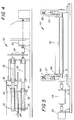
- the assembly 50 further illustrated in Fig. 5, comprises a hard, frictional surface, metering roller 51, which is precision ground and mounted on shaft 53, and a compliant pressure roller 52, also with a precision ground surface, for example, of 60 durometer polyurethane.
- the metering roller 51 is driven by a DC motor 54 controlled with feedback from rotary encoder system 55, having, for example, an effective resolution of 10,160 counts per revolution.
- the pressure roller 52 is supported on it shaft 56 by arms 57, which are slidable vertically in the apparatus mainframe and urged into contact with the metering roller 51 by springs 58, to have, for example, an 8 lbs. nip pressure.
- Sensor 60 is positioned at the output side of the metering rollers 51 as shown in Fig. 2 and provides means for detecting the path position of the lead edge of the strips.
- the sensor can comprise a infrared LED source mounted above the edge of the feed path and a cooperative detector mounted below the path. These elements are positioned so the lead edge of a sheet passing along the sheet guide will interrupt the source light and signal the edge presence.
- sensor 60 The function of sensor 60 is to cooperate with metering assembly 50 to stop the lead ends of the slit strips, at a "zero position", or to jog the strips forward or backward to a predetermined position that is a precisely known distance along the feed path direction from the desired strip cutting position (that is, the position that will yield the precise length for finished sheets F).
- the metering roller is advanced a predetermined number of increments, under control of the encoder system 55, and the finisher apparatus microprocessor control (not shown), to locate the strip ends at the desired cross-cutting position, described above.
- the feed of the entire parent sheet P is controlled by the metering assembly.
- the compliant sheet feed rollers 11 are overridden by the more firm grasp of the metering assembly nip. It is highly preferred, that the cutting nip of knife sets 31, 32 have a velocity equal to, or faster than, the metering roller's peripheral velocity so that a drag force is not created on the strips advance to their cutting position.
- the cutting assembly 70 comprises cooperating cross-cut knives 71, 72, which extend across the feed path, precisely perpendicular to the direction of feed (defined by edge guide 13) and in precise longitudinal alignment with cutting position to which strips are advanced by the metering assembly 50, as just described above.
- the lower knife 71 is stationary and the upper knife 72 is movable, and preloaded against the lower knife 71, to provide a progressive cutting action. That is, the shear angle of the upper knife and the relief angle of the upper knife and the relief angles in both upper and lower knives are selected to achieve progressive point contacts transversely across the cutting position.
- crank assembly 73 see Fig.
- the finisher apparatus 1 can be seen in cooperation with an output conveyor and finished sheet collator 80.
- the sequential arrays of tandem sheets are feed by transfer roller 81, operating over a sheet support plate not shown, into the nips of rollers 83 of the conveyor/collator assembly 80.
- the rollers feed the sheets into an ordered condition and into a collator bin, where an operator can easily remove and insert print stacks to customer envelopes.
Landscapes
- Physics & Mathematics (AREA)
- General Physics & Mathematics (AREA)
- Details Of Cutting Devices (AREA)
- Photographic Processing Devices Using Wet Methods (AREA)
- Control Of Cutting Processes (AREA)
Applications Claiming Priority (2)
| Application Number | Priority Date | Filing Date | Title |
|---|---|---|---|
| US31091794A | 1994-09-22 | 1994-09-22 | |
| US310917 | 1994-09-22 |
Publications (1)
| Publication Number | Publication Date |
|---|---|
| EP0703497A1 true EP0703497A1 (fr) | 1996-03-27 |
Family
ID=23204620
Family Applications (1)
| Application Number | Title | Priority Date | Filing Date |
|---|---|---|---|
| EP95420253A Withdrawn EP0703497A1 (fr) | 1994-09-22 | 1995-09-14 | Appareil pour diviser une feuille mère à images multiples en feuilles discretes, à une seule image et ouvrées |
Country Status (2)
| Country | Link |
|---|---|
| EP (1) | EP0703497A1 (fr) |
| JP (1) | JPH08197492A (fr) |
Cited By (4)
| Publication number | Priority date | Publication date | Assignee | Title |
|---|---|---|---|---|
| GB2334595A (en) * | 1998-02-18 | 1999-08-25 | Alastair Provo Stuart Thain | Cutters and holders for photographic film clip tests |
| EP1195644A3 (fr) * | 2000-10-06 | 2002-12-18 | Eastman Kodak Company | Appareil pour un traitement post-print d'un appareil pour photofinissage |
| DE10308829A1 (de) * | 2003-02-27 | 2004-09-16 | Albin Spitzke Kg (Gmbh & Co) | Verfahren und Vorrichtung zum Herstellen von rechteckigen Zuschnitten aus flächigem Material |
| CN121268001A (zh) * | 2025-12-10 | 2026-01-06 | 江苏旭智冷链科技有限公司 | 一种芯板的同步裁切装置 |
Families Citing this family (2)
| Publication number | Priority date | Publication date | Assignee | Title |
|---|---|---|---|---|
| EP1800797A4 (fr) * | 2004-09-03 | 2011-01-26 | Mitsuboshi Diamond Ind Co Ltd | Appareil et procédé de polissage |
| KR102245144B1 (ko) * | 2020-10-22 | 2021-04-28 | 주식회사 진영엠티 | 장력 센싱 데이터를 기반으로 일정 장력을 유지하는 금속박판 절단장치 |
Citations (7)
| Publication number | Priority date | Publication date | Assignee | Title |
|---|---|---|---|---|
| US3494232A (en) * | 1967-08-10 | 1970-02-10 | Eric S Lindau | Slitter and cutter apparatus |
| US3599521A (en) * | 1969-06-25 | 1971-08-17 | Alves Photo Service Inc | Automatic film cutter |
| US3640161A (en) * | 1970-02-09 | 1972-02-08 | Avant Ind | Method for cutting out individual pictures from a multiple image picture |
| US3929327A (en) | 1974-04-01 | 1975-12-30 | Addressograph Multigraph | Document transport and registration apparatus |
| US4506824A (en) | 1982-02-17 | 1985-03-26 | Lucht Engineering, Inc. | Paper cutter |
| EP0259263A2 (fr) * | 1986-09-02 | 1988-03-09 | GRETAG IMAGING Inc. | Appareil de coupage pour images photographiques |
| US4943270A (en) | 1986-09-02 | 1990-07-24 | Cx Corporation | Photographic print cutter |
-
1995
- 1995-09-14 EP EP95420253A patent/EP0703497A1/fr not_active Withdrawn
- 1995-09-21 JP JP7243120A patent/JPH08197492A/ja active Pending
Patent Citations (7)
| Publication number | Priority date | Publication date | Assignee | Title |
|---|---|---|---|---|
| US3494232A (en) * | 1967-08-10 | 1970-02-10 | Eric S Lindau | Slitter and cutter apparatus |
| US3599521A (en) * | 1969-06-25 | 1971-08-17 | Alves Photo Service Inc | Automatic film cutter |
| US3640161A (en) * | 1970-02-09 | 1972-02-08 | Avant Ind | Method for cutting out individual pictures from a multiple image picture |
| US3929327A (en) | 1974-04-01 | 1975-12-30 | Addressograph Multigraph | Document transport and registration apparatus |
| US4506824A (en) | 1982-02-17 | 1985-03-26 | Lucht Engineering, Inc. | Paper cutter |
| EP0259263A2 (fr) * | 1986-09-02 | 1988-03-09 | GRETAG IMAGING Inc. | Appareil de coupage pour images photographiques |
| US4943270A (en) | 1986-09-02 | 1990-07-24 | Cx Corporation | Photographic print cutter |
Cited By (4)
| Publication number | Priority date | Publication date | Assignee | Title |
|---|---|---|---|---|
| GB2334595A (en) * | 1998-02-18 | 1999-08-25 | Alastair Provo Stuart Thain | Cutters and holders for photographic film clip tests |
| EP1195644A3 (fr) * | 2000-10-06 | 2002-12-18 | Eastman Kodak Company | Appareil pour un traitement post-print d'un appareil pour photofinissage |
| DE10308829A1 (de) * | 2003-02-27 | 2004-09-16 | Albin Spitzke Kg (Gmbh & Co) | Verfahren und Vorrichtung zum Herstellen von rechteckigen Zuschnitten aus flächigem Material |
| CN121268001A (zh) * | 2025-12-10 | 2026-01-06 | 江苏旭智冷链科技有限公司 | 一种芯板的同步裁切装置 |
Also Published As
| Publication number | Publication date |
|---|---|
| JPH08197492A (ja) | 1996-08-06 |
Similar Documents
| Publication | Publication Date | Title |
|---|---|---|
| US6554511B2 (en) | Media cutter and slicer mechanism for a printer | |
| US5765460A (en) | Paper cutter for variable format | |
| DE69402566T2 (de) | System zum Wechseln von Produktspezifikationen in einer Welleinrichtung | |
| DE112011101051B4 (de) | Papierverarbeitungsvorrichtung | |
| US3813976A (en) | Photographic print cutter | |
| DE69902418T2 (de) | Reibungsantriebsgerät für Streifenmaterial | |
| EP0159717A2 (fr) | Dispositif d'empilage à feuille en continu | |
| EP0468374B1 (fr) | Cisaille rotative | |
| DE69905509T2 (de) | Vorrichtung zum Beschneiden von Zeichnungen aus bogen- oder bahnförmigen Materialien | |
| EP1166977B1 (fr) | Machine pour la coupe automatisée d'imprimés | |
| EP1281653A2 (fr) | Dispositif pour le traitement des supports d'impression sous forme de feuilles | |
| DE68925026T2 (de) | Blattabtrennvorrichtung. | |
| EP2529905A1 (fr) | Dispositif et procédé de perforation de feuilles | |
| EP0703497A1 (fr) | Appareil pour diviser une feuille mère à images multiples en feuilles discretes, à une seule image et ouvrées | |
| DE19830489A1 (de) | Schneidvorrichtung für flache Produkte | |
| EP0947880B1 (fr) | Méthode et dispositif pour couper des bandes de matériau pourvues d'images | |
| EP3928936B1 (fr) | Dispositif de découpe | |
| EP2529901A1 (fr) | Dispositif de coupe de sections d'un carton cintré | |
| EP1491303A1 (fr) | Méthode et dispositif pour couper des produits imprimés | |
| DE69400542T2 (de) | Papierschneidvorrichtung | |
| EP0017878A1 (fr) | Appareil pour rogner des piles de feuilles | |
| EP3431236B1 (fr) | Équipement et procédé de découpe transversale de bandes marginales | |
| US4758215A (en) | Photographic paper handling apparatus | |
| DE4107801C2 (de) | Aufzeichnungsträger-Schneidvorrichtung für Druck- oder Kopiergeräte | |
| US6761097B2 (en) | Method for cutting multisize photographic prints |
Legal Events
| Date | Code | Title | Description |
|---|---|---|---|
| PUAI | Public reference made under article 153(3) epc to a published international application that has entered the european phase |
Free format text: ORIGINAL CODE: 0009012 |
|
| AK | Designated contracting states |
Kind code of ref document: A1 Designated state(s): DE FR GB |
|
| 17P | Request for examination filed |
Effective date: 19960902 |
|
| STAA | Information on the status of an ep patent application or granted ep patent |
Free format text: STATUS: THE APPLICATION HAS BEEN WITHDRAWN |
|
| 18W | Application withdrawn |
Withdrawal date: 19990521 |