EP0703518A1 - System zur Regelung der Position eines Luftdurchlassventils und Belüftungsvorrichtung mit einem derartigen System - Google Patents
System zur Regelung der Position eines Luftdurchlassventils und Belüftungsvorrichtung mit einem derartigen System Download PDFInfo
- Publication number
- EP0703518A1 EP0703518A1 EP95202583A EP95202583A EP0703518A1 EP 0703518 A1 EP0703518 A1 EP 0703518A1 EP 95202583 A EP95202583 A EP 95202583A EP 95202583 A EP95202583 A EP 95202583A EP 0703518 A1 EP0703518 A1 EP 0703518A1
- Authority
- EP
- European Patent Office
- Prior art keywords
- signal
- air valve
- ventilating device
- temperature
- magnitude
- Prior art date
- Legal status (The legal status is an assumption and is not a legal conclusion. Google has not performed a legal analysis and makes no representation as to the accuracy of the status listed.)
- Granted
Links
Images

Classifications
-
- G—PHYSICS
- G05—CONTROLLING; REGULATING
- G05D—SYSTEMS FOR CONTROLLING OR REGULATING NON-ELECTRIC VARIABLES
- G05D7/00—Control of flow
- G05D7/06—Control of flow characterised by the use of electric means
- G05D7/0617—Control of flow characterised by the use of electric means specially adapted for fluid materials
- G05D7/0629—Control of flow characterised by the use of electric means specially adapted for fluid materials characterised by the type of regulator means
- G05D7/0635—Control of flow characterised by the use of electric means specially adapted for fluid materials characterised by the type of regulator means by action on throttling means
-
- F—MECHANICAL ENGINEERING; LIGHTING; HEATING; WEAPONS; BLASTING
- F24—HEATING; RANGES; VENTILATING
- F24F—AIR-CONDITIONING; AIR-HUMIDIFICATION; VENTILATION; USE OF AIR CURRENTS FOR SCREENING
- F24F11/00—Control or safety arrangements
- F24F11/70—Control systems characterised by their outputs; Constructional details thereof
- F24F11/72—Control systems characterised by their outputs; Constructional details thereof for controlling the supply of treated air, e.g. its pressure
- F24F11/74—Control systems characterised by their outputs; Constructional details thereof for controlling the supply of treated air, e.g. its pressure for controlling air flow rate or air velocity
- F24F11/75—Control systems characterised by their outputs; Constructional details thereof for controlling the supply of treated air, e.g. its pressure for controlling air flow rate or air velocity for maintaining constant air flow rate or air velocity
Definitions
- the invention relates to a system for controlling the position of an air passage valve, in particular the air passage valve of a ventilating device.
- Ventilating devices comprising an air passage valve are generally known and can be incorporated into a door casing or window casing, with the ventilating device often extending throughout the width of the door or the window.
- the ventilating device has a ventilating grate through which an air flow passes whose magnitude can be varied by adjusting the position of the air valve.
- the air valve can be a pivoting valve as well as a sliding valve.
- NL-A-8401388 An example of such a ventilating device is described in NL-A-8401388. Further, DE-A-3303987 describes a ventilating device which forms part of a channel-shaped climate control system, while it is observed that the extent of opening of the ventilating openings, settable through rotation or sliding, can be controlled by means of adjusting motors. However, this publication does not at all describe in what manner such a control can be realized.
- a ventilating device of the above-described type is adapted to let an air flow pass the ventilating grate at a predetermined flow rate, independently of the wind velocity along the facade.
- Ventilating devices are known whose ventilating area is controlled by one or several slats horizontally disposed one above the other, each having, in cross section, the same configuration as the cross section of a wing of an aeroplane. According as the air velocity through the grate, i.e. the wind pressure on the facade, increases, these slats close, so that a sort of automatic control is obtained.
- the adjustment of this control should be carried out in a skilled manner and it can be expected that, with the passage of time, the controlling action becomes problematic, for instance due to contamination of the slats.
- the object of the invention is to provide a system for the automatic control of the position of an air valve of a ventilating device to enable the air flow rate thus to be maintained at a fixed, predetermined value, which system is so cheap that it can without economical drawbacks be incorporated into (existing types of) ventilating devices for houses and buildings.
- Another object of the invention is to provide such a system that is insusceptible to contamination and whose operation remains reliable also in the longer term.
- the invention provides a system of the above-mentioned type, characterized in that the system comprises a sensor adapted to detect the velocity of an air flow along the air valve or through an opening in the vicinity of the air valve and to provide a signal whose magnitude is representative of the flow rate of the air flow, which signal is fed to an operating element for the position of the air valve.
- the invention provides a system characterized in that the sensor comprises a circuit consisting of a first temperature-sensitive element and a second temperature-sensititive element, means being provided for heating the first temperature-sensitive element and the two temperature-sensitive elements being intended to be disposed in an opening whose size is determined by the position of the air valve or in an opening of a fixed size in the vicinity of the air valve; that the first and the second temperature-sensitive element are included in a circuit determining the difference between a specific property of the first and the second temperature-sensitive element, which property varies depending on the air flow velocity, a computing circuit which converts this difference into a pulse-width signal that depends on the magnitude of the difference, and a servomotor whose output shaft is coupled to the air valve and determines the position thereof, of which output shaft the position is determined by the width of the pulses fed at the input thereof.
- sensors are available on the market capable of providing a signal that is a measure for the speed of an air flow.
- the price of one such sensor is a multiple of the current price of a complete ventilating grate, so that these known sensors are not applicable for economical reasons.
- US-A-4199981 describes a sensor intended to be used in a system for controlling a flow of fluid.
- This known sensor comprises a bridge circuit with a preheated resistor, with which the speed of the fluids can be detected as it influences the temperature of the preheated resistor. Via an amplifying circuit, the output signal of the bridge circuit controls a servomotor which control a valve in the flow of fluid.
- this publication contains no indication whatsoever that such type of sensor could also be used for measuring the magnitude of an air flow.
- the invention also provides a ventilating device having an air valve provided with a system of the above-described type.
- the air valve can be of the pivoting type, of the rotating type or of the sliding type.
- each of the temperature-sensitive elements is a temperature-sensitive resistor, for instance a resistor with a positive temperature coefficient, each resistor being incorporated into one branch of a bridge circuit, the output of the bridge circuit being coupled to a comparator whose output signal is fed to a microprocessor that provides a signal having a pulse width that depends on the output signal of the comparator.
- the pulse width gradually increases or decreases to the new value of the pulse width determined by the new output signal.
- a temperature detector to the computing circuit, typically a microprocessor, in order that, above or below a specific temperature, the ventilating device is automatically opened or closed entirely.
- the system according to the invention essentially consists of four parts: a bridge circuit 1, a comparator circuit 2, a microprocessor 3 and a servomotor 4, whose shaft is coupled to the air valve of a ventilating device to enable variation of the position of this valve.
- a bridge circuit 1 a comparator circuit 2
- a microprocessor 3 a microprocessor 3
- a servomotor 4 whose shaft is coupled to the air valve of a ventilating device to enable variation of the position of this valve.
- the bridge circuit comprises two temperature-sensitive elements 11 and 12, according to the invention resistors having a positive temperature coefficient, while in the vicinity of resistor 11 a heating element, for instance a heating coil 15, is disposed with which the element 11 is heated to a temperature that is clearly above the ambient temperature.
- the bridge circuit further comprises a resistor 13 and a settable resistor 14.
- the resistors 13 and 11 are interconnected in series between a positive and a negative supply voltage line, 5 and 6 respectively, and the resistors 14 and 12 are likewise interconnected in series between the same supply voltage lines.
- the output signal of the bridge circuit is present between on the one hand the nodal point of the resistors 13 and 11 and on the other hand the nodal point of the resistors 12 and 14. By means of the resistor 14, the bridge balance
- the output signal of the bridge circuit 1 is fed to the inverting and the non-inverting input of an operational amplifier 20, which forms the main component of the comparator 2 and whose output is fed back via a resistor 23 to the inverting input of the operational amplifier.
- the comparator provides a signal proportional to the difference between the resistor value of the PTC resistor 11 and that of the PTC resistor 12.
- This signal which, in the first embodiment of the invention, as shown in Fig. 2, is proportional to the air velocity through the ventilation outflow openings of the grate, is fed to the input 31 of a microprocessor 30.
- This microprocessor is programmed to provide, at the output 32 thereof, a pulse-shaped signal whose pulse width depends on the magnitude of the signal at the input 31.
- a table can be incorporated into the memory of the microprocessor, which table contains for a large series of output signal values of the comparator 2 a corresponding value for the pulse width of the pulse-shaped signal at the output 32. Accordingly, this table should once be determined for each type of ventilating device and can then be stored in the memory for all devices of that type. For instance, in the table so many different values of the output signal of the comparator 2 can be stored that the air valve is controlled with steps of 0.2 mm.
- a third possibility is to dispose the temperature-sensitive elements 11 and 12 in or near one of the openings of the ventilating grate, which opening is varied in size by the ventilating valve. Accordingly, there is a more direct connection between the magnitude of the air flow along the temperature-sensitive elements and the magnitude of the air flow through the grate.
- the output signal of the comparator can then also be a direct measure for the air flow rate that actually passes through the ventilating grate, so that the use of a table is not required.
- a fourth possibility is to use, instead of temperature-sensitive elements, pressure-sensitive elements, for instance a differential pressure detector consisting of for instance two pressure sensors provided on both sides of an orifice meter, of which pressure sensors the output signal can be connected to the bridge circuit instead of the resistors 11 and 12.
- pressure-sensitive elements for instance a differential pressure detector consisting of for instance two pressure sensors provided on both sides of an orifice meter, of which pressure sensors the output signal can be connected to the bridge circuit instead of the resistors 11 and 12.
- pressure sensors can be used both in a fixed opening in the ventilating device and in an opening varied in size by the ventilating valve.
- the output signal at the output 32 can be a continuous flow of pulse-shaped signals, but it is also possible to provide a brief series of pulses only upon variation of the signal at the input 31.
- the microprocessor further has a clock input 33 to which a clock signal is fed from a clock signal generator 34 known per se.
- the output signal of the output 32 of the microprocessor is coupled to the control input 41 of the servomotor.
- the microprocessor comprises two further inputs 35 and 37. When, by the closing of a switch 36, input 35 is connected to the negative supply voltage line 6, the microprocessor provides at the output a pulse signal having a first predetermined pulse width such that the servomotor 40 opens the ventilating valve completely.
- the microprocess When, by the closing of a switch 38, the input 37 is connected to the zero-volt supply voltage line 6, the microprocess provides at the output 32 thereof a signal having a second predetermined pulse width such that the servomotor 40 closes the ventilating valve completely.
- Servomotors that are suitable for use with the system according to the invention are generally available, suitable types are for instance the types C507 -C509 of the brand Graupner or the type HS 300 of the type Hitec. In this manner, the occupant of the building wherein the ventilating device is located can, if so desired, open or close the air valve completely, independently of the actual air flow through the ventilating grate.
- a temperature detector may be provided which is active for one or more ventilating devices and which, when the temperature inside or outside the building wherein the ventilating device(s) is (are) located rises above a specific value, operates the switch 36 to open the air valve completely, and which, when the temperature drops below a specific value, operates the switch 38 to close the valve completely.
- the air valve is always diplaced in one direction toward its position to be assumed. This means, that when the air valve is further opened, the end position is reached by first opening the air valve further than desired, and then bringing it to the calculated end position. Closing of the air valve is then effected by bringing the air valve directly to the calculated end position.
- a control in opposite direction is also possible.
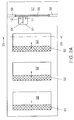
- Fig. 2a shows very diagrammatically how the PCT resistors 11 and 12 are disposed in a rectangular measuring channel 51 provided in a ventilating device.
- a ventilating device 50 of the sliding type with air outlet openings 52 and a slidable air valve 53 is shown.
- the ventilating device shown is a so-called silencer wherein provisions are made for minimizing the transmission of noise from the inlet opening 55 to the outlet opening 52.
- the invention can also be applied in conventional ventilating grates.
- the measuring channel 51 containing the sensor 11, 12 is provided in the ventilating device so that it extends from the inlet opening 54 to the space behind the air valve or slide. In this manner, all air passing the measuring channel must also pass this valve or slide, because the space wherein the measuring channel terminates is in open communication with the space behind the valve or slide. In this manner, turbulence around the sensor, which may cause measuring errors, is avoided and the signal provided by the sensor is a direct or indirect measure for the air velocity through the grate and independent of the dimensions of the grate and of the size of the inlet openings thereof.
- the measuring channel can also continue from the inlet opening 55 right to the front face of the ventilating device, so that it terminates in the face wherein the outflow openings 53 are also located.
- the output signal of the sensor forms no direct measure for the air velocity through the grate and tables should be used in the manner as described hereinabove.
- the senor consisting of the resistors 11 and 12
- the sensor can also be disposed in one of the openings 53, with the signal provided by the sensor exhibiting a more direct connection with the flow rate of the air flow through the opening 52.
- the resistor 11 is heated and disposed so as to be located in the air flow which also passes through the ventilating device and the resistor 12 is likewise disposed in the air flow, but is thermally insulated from the resistor 11 by means of a heat-resistant partition 54, so that the heat thereof does not influence the resistance value of the resistor 12.
- the heating of the resistor 11 can for instance take place by providing it on a ceramic substrate and surrounding it with a strip of a relatively high resistance wherein, by means of a suitable current value, the desired heat is generated.
- the magnitude of the air flow along both the resistor 11 and the resistor 12 depends on the pressure difference over the ventilating device and provides the desired signal for controlling the servomotor, a greater air flow will provide that both the resistor 12 and the resistor 11 cool down, but as the resistor 11 is artificially maintained at a higher temperature than the ambient temperature, the cooling of this resistor is relatively greater than the cooling of the resistor 12. It has appeared that in this manner, over a large range of ambient temperatures, a signal is provided by the bridge circuit 1, which signal exclusively depends on the magnitude of the air flow through the opening 21 or through the opening 52.
- the sensor 11, 12 is mounted on a printed circuit-board shown in Fig. 2a, slid into the ventilating device in rails 58 so that it can readily be removed for servicing.
- the other side of the pinted circuit-board mounts the other components diagrammatically shown in Fig. 1, with the exception of the servomotor 40, which is mounted on the slidable grate 52. These components are accommodated in a compartment 57 of the ventilating device so as to be shielded against external influences.
- a differential pressure sensor for instance consisting of two pressure sensors, each on one side of an orifice meter, can either be disposed in the measuring channel 51 or in an opening 53.
Landscapes
- Physics & Mathematics (AREA)
- Engineering & Computer Science (AREA)
- Fluid Mechanics (AREA)
- General Physics & Mathematics (AREA)
- Automation & Control Theory (AREA)
- Chemical & Material Sciences (AREA)
- Combustion & Propulsion (AREA)
- Mechanical Engineering (AREA)
- General Engineering & Computer Science (AREA)
- Ventilation (AREA)
- Flow Control (AREA)
- Electrically Driven Valve-Operating Means (AREA)
Applications Claiming Priority (4)
| Application Number | Priority Date | Filing Date | Title |
|---|---|---|---|
| NL9401554A NL9401554A (nl) | 1994-09-23 | 1994-09-23 | Stelsel voor het automatisch regelen van de stand van een luchtdoorlaatklep, alsmede een ventilatieinrichting voorzien van een dergelijk stelsel. |
| NL9401554 | 1994-09-23 | ||
| NL9500205A NL9500205A (nl) | 1994-09-23 | 1995-02-03 | Stelsel voor het automatisch regelen van de stand van een luchtdoorlaatklep, alsmede een ventilatieinrichting voorzien van een dergelijk stelsel. |
| NL9500205 | 1995-02-03 |
Publications (2)
| Publication Number | Publication Date |
|---|---|
| EP0703518A1 true EP0703518A1 (de) | 1996-03-27 |
| EP0703518B1 EP0703518B1 (de) | 2000-05-10 |
Family
ID=26647256
Family Applications (1)
| Application Number | Title | Priority Date | Filing Date |
|---|---|---|---|
| EP95202583A Expired - Lifetime EP0703518B1 (de) | 1994-09-23 | 1995-09-25 | Belüftungsvorrichtung zur Regelung der Position eines Luftdurchlassventils |
Country Status (3)
| Country | Link |
|---|---|
| EP (1) | EP0703518B1 (de) |
| DE (1) | DE69516786T2 (de) |
| NL (1) | NL9500205A (de) |
Cited By (1)
| Publication number | Priority date | Publication date | Assignee | Title |
|---|---|---|---|---|
| GB2436624A (en) * | 2006-03-31 | 2007-10-03 | Nuaire Ltd | Fluid flow control device |
Families Citing this family (1)
| Publication number | Priority date | Publication date | Assignee | Title |
|---|---|---|---|---|
| NL1005147C2 (nl) | 1997-01-31 | 1998-08-03 | Brakel Atmos B V | Gebouw. |
Citations (5)
| Publication number | Priority date | Publication date | Assignee | Title |
|---|---|---|---|---|
| US3757808A (en) * | 1972-07-21 | 1973-09-11 | Garrett Corp | Electronic mass airflow sensing and control system |
| US4199981A (en) | 1977-02-16 | 1980-04-29 | Wen Young | Flow control device for fluids flowing in a closed conduit |
| DE3303987A1 (de) | 1983-02-05 | 1984-08-09 | Emil Dipl.-Ing. Koch (FH), 7300 Esslingen | Kanalsystem insbes. fuer lueftungs- und klimaanlagen |
| NL8401388A (nl) | 1984-05-02 | 1985-12-02 | Heycop Beheer Bv | Ventilatieinrichting te plaatsen in een deur- of raamkozijn aansluitend op een isolerende ruit. |
| US4926903A (en) * | 1989-05-05 | 1990-05-22 | Tomoe Technical Research Company | Butterfly valve having a function for measuring a flow rate and method of measuring a flow rate with a butterfly valve |
-
1995
- 1995-02-03 NL NL9500205A patent/NL9500205A/xx not_active Application Discontinuation
- 1995-09-25 EP EP95202583A patent/EP0703518B1/de not_active Expired - Lifetime
- 1995-09-25 DE DE69516786T patent/DE69516786T2/de not_active Expired - Lifetime
Patent Citations (5)
| Publication number | Priority date | Publication date | Assignee | Title |
|---|---|---|---|---|
| US3757808A (en) * | 1972-07-21 | 1973-09-11 | Garrett Corp | Electronic mass airflow sensing and control system |
| US4199981A (en) | 1977-02-16 | 1980-04-29 | Wen Young | Flow control device for fluids flowing in a closed conduit |
| DE3303987A1 (de) | 1983-02-05 | 1984-08-09 | Emil Dipl.-Ing. Koch (FH), 7300 Esslingen | Kanalsystem insbes. fuer lueftungs- und klimaanlagen |
| NL8401388A (nl) | 1984-05-02 | 1985-12-02 | Heycop Beheer Bv | Ventilatieinrichting te plaatsen in een deur- of raamkozijn aansluitend op een isolerende ruit. |
| US4926903A (en) * | 1989-05-05 | 1990-05-22 | Tomoe Technical Research Company | Butterfly valve having a function for measuring a flow rate and method of measuring a flow rate with a butterfly valve |
Cited By (2)
| Publication number | Priority date | Publication date | Assignee | Title |
|---|---|---|---|---|
| GB2436624A (en) * | 2006-03-31 | 2007-10-03 | Nuaire Ltd | Fluid flow control device |
| GB2436624B (en) * | 2006-03-31 | 2012-01-11 | Nuaire Ltd | Fluid Flow Control Apparatus |
Also Published As
| Publication number | Publication date |
|---|---|
| EP0703518B1 (de) | 2000-05-10 |
| DE69516786T2 (de) | 2001-01-25 |
| DE69516786D1 (de) | 2000-06-15 |
| NL9500205A (nl) | 1996-05-01 |
Similar Documents
| Publication | Publication Date | Title |
|---|---|---|
| CA1296793C (en) | Bypass controller and bypass system | |
| EP3812870B1 (de) | Durchflussregelsystem | |
| US6463397B1 (en) | Environmental monitoring and control system for a ventilated cage and rack system | |
| US4392417A (en) | Variable dead band pressure control system | |
| WO1989005947A1 (en) | Method and apparatus for the control of air flows and pressures in air-conditioning | |
| EP1264160B1 (de) | Verfahren und vorrichtung zur messung und regelung einer flüssigkeitsströmung | |
| US6430985B1 (en) | Multiple point calibrated HVAC flow rate controller | |
| GB1438684A (en) | Fluid flow rate control system | |
| US20080045132A1 (en) | Set And Forget Exhaust Controller | |
| US4257318A (en) | Variable dead band pressure control system | |
| US5207379A (en) | Cascaded control apparatus for controlling unit ventilators | |
| EP0703518B1 (de) | Belüftungsvorrichtung zur Regelung der Position eines Luftdurchlassventils | |
| EP0518131B1 (de) | Einrichtung zur Steuerung von Klimageräten | |
| JPH0763404A (ja) | 空気調和機 | |
| US4585163A (en) | Variable air volume system control | |
| GB2222705A (en) | Reduced pressure enclosure | |
| US4838484A (en) | Variable volume air conditioning system with velocity readout at the thermostat | |
| JPS6273025A (ja) | 室内圧力制御方法 | |
| WO1999041553A1 (en) | Hygrometer for humidity and ventilation control | |
| JP2661274B2 (ja) | 空気調和機 | |
| NL9401554A (nl) | Stelsel voor het automatisch regelen van de stand van een luchtdoorlaatklep, alsmede een ventilatieinrichting voorzien van een dergelijk stelsel. | |
| NL1001340C2 (nl) | Ventilatiesysteem voorzien van een ventilatie-inrichting met een luchtstroomrichtingssensor. | |
| JPH03236540A (ja) | エアハンドリングユニットのダンパー制御装置 | |
| AU635695B1 (en) | Laboratory fume hood control apparatus having improved safety considerations | |
| JPH0351657A (ja) | 空気調和機 |
Legal Events
| Date | Code | Title | Description |
|---|---|---|---|
| PUAI | Public reference made under article 153(3) epc to a published international application that has entered the european phase |
Free format text: ORIGINAL CODE: 0009012 |
|
| AK | Designated contracting states |
Kind code of ref document: A1 Designated state(s): BE DE GB NL |
|
| 17P | Request for examination filed |
Effective date: 19960419 |
|
| 17Q | First examination report despatched |
Effective date: 19980709 |
|
| GRAG | Despatch of communication of intention to grant |
Free format text: ORIGINAL CODE: EPIDOS AGRA |
|
| RTI1 | Title (correction) |
Free format text: VENTILATING DEVICE FOR CONTROLLING THE POSITION OF AN AIR PASSAGE VALVE |
|
| GRAG | Despatch of communication of intention to grant |
Free format text: ORIGINAL CODE: EPIDOS AGRA |
|
| GRAH | Despatch of communication of intention to grant a patent |
Free format text: ORIGINAL CODE: EPIDOS IGRA |
|
| GRAH | Despatch of communication of intention to grant a patent |
Free format text: ORIGINAL CODE: EPIDOS IGRA |
|
| GRAA | (expected) grant |
Free format text: ORIGINAL CODE: 0009210 |
|
| AK | Designated contracting states |
Kind code of ref document: B1 Designated state(s): BE DE GB NL |
|
| REF | Corresponds to: |
Ref document number: 69516786 Country of ref document: DE Date of ref document: 20000615 |
|
| EN | Fr: translation not filed | ||
| PLBE | No opposition filed within time limit |
Free format text: ORIGINAL CODE: 0009261 |
|
| 26N | No opposition filed | ||
| REG | Reference to a national code |
Ref country code: GB Ref legal event code: IF02 |
|
| NLUE | Nl: licence registered with regard to european patents |
Effective date: 20020701 |
|
| NLS | Nl: assignments of ep-patents |
Owner name: ALUSTA NATUURLIJKE VENTILATIETECHNIEK B.V. Effective date: 20050607 |
|
| PGFP | Annual fee paid to national office [announced via postgrant information from national office to epo] |
Ref country code: NL Payment date: 20100916 Year of fee payment: 16 |
|
| PGFP | Annual fee paid to national office [announced via postgrant information from national office to epo] |
Ref country code: DE Payment date: 20101022 Year of fee payment: 16 |
|
| PGFP | Annual fee paid to national office [announced via postgrant information from national office to epo] |
Ref country code: GB Payment date: 20101021 Year of fee payment: 16 Ref country code: BE Payment date: 20101022 Year of fee payment: 16 |
|
| BERE | Be: lapsed |
Owner name: *ZWAAN ADRIANUS JACOBUS Effective date: 20110930 |
|
| REG | Reference to a national code |
Ref country code: NL Ref legal event code: V1 Effective date: 20120401 |
|
| GBPC | Gb: european patent ceased through non-payment of renewal fee |
Effective date: 20110925 |
|
| PG25 | Lapsed in a contracting state [announced via postgrant information from national office to epo] |
Ref country code: BE Free format text: LAPSE BECAUSE OF NON-PAYMENT OF DUE FEES Effective date: 20110930 |
|
| REG | Reference to a national code |
Ref country code: DE Ref legal event code: R119 Ref document number: 69516786 Country of ref document: DE Effective date: 20120403 |
|
| PG25 | Lapsed in a contracting state [announced via postgrant information from national office to epo] |
Ref country code: DE Free format text: LAPSE BECAUSE OF NON-PAYMENT OF DUE FEES Effective date: 20120403 Ref country code: NL Free format text: LAPSE BECAUSE OF NON-PAYMENT OF DUE FEES Effective date: 20120401 |
|
| PG25 | Lapsed in a contracting state [announced via postgrant information from national office to epo] |
Ref country code: GB Free format text: LAPSE BECAUSE OF NON-PAYMENT OF DUE FEES Effective date: 20110925 |