EP0703520B1 - Schalthebel für ein Kraftfahrzeuggetriebe - Google Patents
Schalthebel für ein Kraftfahrzeuggetriebe Download PDFInfo
- Publication number
- EP0703520B1 EP0703520B1 EP95112034A EP95112034A EP0703520B1 EP 0703520 B1 EP0703520 B1 EP 0703520B1 EP 95112034 A EP95112034 A EP 95112034A EP 95112034 A EP95112034 A EP 95112034A EP 0703520 B1 EP0703520 B1 EP 0703520B1
- Authority
- EP
- European Patent Office
- Prior art keywords
- gearshift lever
- shift lever
- pins
- snap
- gear
- Prior art date
- Legal status (The legal status is an assumption and is not a legal conclusion. Google has not performed a legal analysis and makes no representation as to the accuracy of the status listed.)
- Expired - Lifetime
Links
- 210000002105 tongue Anatomy 0.000 abstract description 16
- 230000005540 biological transmission Effects 0.000 description 6
- 238000010276 construction Methods 0.000 description 1
- 238000001746 injection moulding Methods 0.000 description 1
- 239000000463 material Substances 0.000 description 1
Images
Classifications
-
- G—PHYSICS
- G05—CONTROLLING; REGULATING
- G05G—CONTROL DEVICES OR SYSTEMS INSOFAR AS CHARACTERISED BY MECHANICAL FEATURES ONLY
- G05G1/00—Controlling members, e.g. knobs or handles; Assemblies or arrangements thereof; Indicating position of controlling members
- G05G1/04—Controlling members for hand actuation by pivoting movement, e.g. levers
- G05G1/06—Details of their grip parts
-
- F—MECHANICAL ENGINEERING; LIGHTING; HEATING; WEAPONS; BLASTING
- F16—ENGINEERING ELEMENTS AND UNITS; GENERAL MEASURES FOR PRODUCING AND MAINTAINING EFFECTIVE FUNCTIONING OF MACHINES OR INSTALLATIONS; THERMAL INSULATION IN GENERAL
- F16H—GEARING
- F16H59/00—Control inputs to control units of change-speed- or reversing-gearings for conveying rotary motion
- F16H59/02—Selector apparatus
- F16H59/0278—Constructional features of the selector lever, e.g. grip parts, mounting or manufacturing
- F16H2059/0282—Lever handles with lock mechanisms, e.g. for allowing selection of reverse gear or releasing lever from park position
Definitions
- the invention relates to a shift lever for a Motor vehicle transmission according to the preamble of the main claim.
- DE-A-4 217 500 shows a genus-like one Shift lever, in which a shift lever rod with a Sleeve part is locked, the shift lever rod above and below the locking shown in the inner bore is guided with a precise fit.
- the object of the invention is therefore to provide a known one shift levers installed in motor vehicles of the applicant so that on the one hand the control handle is held securely on the shift lever rod on the other hand, the withdrawal forces are reasonable Limits are kept.
- the shift lever rod is accordingly guided top and bottom ends of the sleeve while in between the locking tongues are arranged.
- initiated forces are supported both above and from the bottom without using a force component act on the locking tongues.
- the locking tabs can accordingly solely on the basis of a reasonable deduction force or a secure fit of the control handle will.
- the locking tongues are made of the sleeve wall of a receiving sleeve inserted in the control handle shaped. In the simplest case, this can be done with U-shaped or V-shaped free cuts inside reach the sleeve wall.
- the locking tongues Similar as in the prior art have locking lugs which in engage an appropriate annular groove in the gear lever rod.
- the locking lugs extend in the circumferential direction, while the legs of the U-shaped or V-shaped Cut-outs aligned with the longitudinal axis of the sleeve are.
- Such a shift lever is suitable for both an automatic transmission, in which the speed steps are preselected and the individual gears are automatically engaged as also for a so-called manual transmission, in which the Driver the respective gear directly via the gear lever inserted.
- the automatic transmission occurs in the Usually only one direction of actuation, namely in the longitudinal direction of the vehicle on. In this case it is advisable the locking tongues perpendicular to this direction of actuation order, because it is possible in this way, the Shift lever end in relation to the level of the actuation direction to run along its entire length.
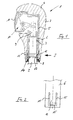
- a shift lever 1 only partially shown for a Automatic motor vehicle transmission not shown consists of one indicated in Figure 1 Shift lever rod 2 and one on the end of the shift lever rod 2 attached control handle 3.
- the control handle 3 has an outer casing 4, into which an insert 5 is embedded. The use 5 goes in the area of used shift lever rod 2 in a receiving sleeve 6 about.
- the sleeve wall forms the inner bore in the sense of the invention.
- the inside diameter of the sleeve is on the Outside diameter of the shift lever rod 2 matched and in such a way that they have two guides, an upper one Guide 7 and a lower guide 8, which with the lateral surface of the shift lever rod 2 in sliding Stand fit. Sliding fit guidance is said in this Context mean that the control handle without noticeable Resistance is pushed over the end of the shift lever rod can be. However, no game should occur.
- the shift lever rod 2 is also articulated on one not shown vehicle-fixed bearing block.
- it takes a locking rod 9 axially displaceable on the (also not shown) with a vehicle-fixed Backdrop works together.
- the locking bar 9 can by a push button 11 and a total mechanism designated 10 are moved upward so that the shift lever 1 can be adjusted, for example in the drawing plane from left to right or into the plane of the drawing.
- the definition of the shift handle 1 on the shift lever rod 2 happens via resilient locking tongues 12 with in the circumferential direction locking lugs 13 in a Engage the annular groove 14 in the shift lever rod 2.
- FIG 2 is the right in the direction of arrow I.
- Locking tongue 12 shown. It is out of the wall of the sleeve 6 shaped and in such a way that a U-shaped free cut 15, in which the U-leg in the longitudinal axis of the sleeve run, the locking tongue 12 forms.
- a U-shaped free cut 15 in which the U-leg in the longitudinal axis of the sleeve run, the locking tongue 12 forms.
- the locking tongues 12 can be slightly inward be curved. This and also the shape of the latch can not then only by the described cut can be achieved. The part is in this case made by injection molding or in a similar manner.
Landscapes
- Engineering & Computer Science (AREA)
- General Engineering & Computer Science (AREA)
- Mechanical Engineering (AREA)
- Physics & Mathematics (AREA)
- General Physics & Mathematics (AREA)
- Automation & Control Theory (AREA)
- Arrangement Or Mounting Of Control Devices For Change-Speed Gearing (AREA)
- Control Of Transmission Device (AREA)
Description
- Figur 1
- den oberen Teil eines Schalthebels für ein automatisches Kraftfahrzeuggetriebe und
- Figur 2
- eine Teilansicht entsprechend dem Pfeil I nach Figur 1.
Claims (3)
- Schalthebel für ein Kraftfahrzeuggetriebe mit einer Schalthebelstange (2), die zum Schalten der einzelnen Gänge oder Fahrstufen gelenkig an einem fahrzeugfesten Lagerbock angeordnet ist und die an ihrem in den Fahrzeuginnenraum ragenden Endabschnitt einen lösbar an ihr befestigten Schaltgriff (3) in der Weise aufnimmt, daß das Schalthebelende in eine Innenbohrung des Schaltgriffs eingeführt und über aus der Bohrungswand geformte, federnd gegen die Schalthebelstange drückende Rastzungen (12) gehalten ist,
dadurch gekennzeichnet,
daß das Ende der Schalthebelstange (2) mit Spiel in der Innenbohrung aufgenommen ist und oberhalb und unterhalb der Rastzungen (12) in der Innenbohrung durch jeweils eine Führungsstelle (7, 8) geführt ist. - Schalthebel nach Anspruch 1, bei dem die Innenbohrung durch eine in den Schaltgriff (3) eingesetzte Hülse (5) gebildet ist, wobei die Rastzungen (12) Teil der Hülsenwand sind und gegen die Schalthebelstange (2) gerichtete in Umfangsrichtung verlaufende Rastnasen (13) aufweisen, die in eine Ringnut (14) der Schalthebelstange eingreifen, dadurch gekennzeichnet, daß die Rastzungen (12) durch U- oder V-ähnliche, in Hülsenlängsachse ausgerichtete Freischnitte (15) aus der Hülsenwand gebildet sind.
- Schalthebel nach Anspruch 2, dadurch gekennzeichnet, daß die Rastzungen (12) in etwa senkrecht zur Betätigungsrichtung des Schalthebels (1) angeordnet sind.
Applications Claiming Priority (2)
| Application Number | Priority Date | Filing Date | Title |
|---|---|---|---|
| DE4434135 | 1994-09-24 | ||
| DE4434135A DE4434135A1 (de) | 1994-09-24 | 1994-09-24 | Schalthebel für ein Kraftfahrzeuggetriebe |
Publications (2)
| Publication Number | Publication Date |
|---|---|
| EP0703520A1 EP0703520A1 (de) | 1996-03-27 |
| EP0703520B1 true EP0703520B1 (de) | 1998-01-07 |
Family
ID=6529083
Family Applications (1)
| Application Number | Title | Priority Date | Filing Date |
|---|---|---|---|
| EP95112034A Expired - Lifetime EP0703520B1 (de) | 1994-09-24 | 1995-07-31 | Schalthebel für ein Kraftfahrzeuggetriebe |
Country Status (3)
| Country | Link |
|---|---|
| EP (1) | EP0703520B1 (de) |
| DE (2) | DE4434135A1 (de) |
| ES (1) | ES2112589T3 (de) |
Families Citing this family (14)
| Publication number | Priority date | Publication date | Assignee | Title |
|---|---|---|---|---|
| SE510776C2 (sv) * | 1997-05-20 | 1999-06-21 | Voac Hydraulics Ab | Ergonomiskt utformad spak |
| DE59803077D1 (de) | 1997-07-11 | 2002-03-21 | Hkr Haas Gmbh & Co Kunststoff | Wählhebel für automatikgetriebe |
| FR2774782B1 (fr) * | 1998-02-06 | 2000-03-10 | Renault | Procede de montage d'un pommeau de prise en main sur un levier de changement de vitesses, et levier de changement de vitesses correspondant |
| DE19941796A1 (de) * | 1999-09-02 | 2001-03-22 | United Parts Fhs Automobil Sys | Wählgriff eines Kraftfahrzeuges |
| US6877396B2 (en) | 1999-09-02 | 2005-04-12 | United Parts Fhs Automobil Systeme Gmbh | Gear shift handle with push button mechanism for an automatic transmission in motor vehicles |
| US6915718B2 (en) | 1999-09-02 | 2005-07-12 | United Parts Fhs Automobil Systeme Gmbh | Selector handle in a motor vehicle |
| DE19941795C1 (de) * | 1999-09-02 | 2001-01-18 | United Parts Fhs Automobil Sys | Automatikschaltgriff mit Druckmechanismus |
| JP2002002321A (ja) | 2000-06-27 | 2002-01-09 | Fuji Kiko Co Ltd | シフトレバー装置のシフトノブ構造 |
| DE10158934A1 (de) | 2001-12-03 | 2003-06-12 | Zf Lemfoerder Metallwaren Ag | Schaltknauf |
| JP4101703B2 (ja) | 2003-06-11 | 2008-06-18 | 富士機工株式会社 | シフトレバー装置 |
| JP5385866B2 (ja) * | 2010-06-30 | 2014-01-08 | 富士機工株式会社 | 車両用シフトレバー装置のシフトノブ装着構造 |
| JP5616846B2 (ja) * | 2011-05-31 | 2014-10-29 | 富士機工株式会社 | 車両用シフトレバー装置のシフトノブ装着構造 |
| JP6695185B2 (ja) * | 2016-03-25 | 2020-05-20 | 富士機工株式会社 | シフトレバー装置 |
| FR3063687B1 (fr) * | 2017-03-08 | 2019-03-29 | Peugeot Citroen Automobiles Sa | Dispositif de commande de boite de vitesse avec verouillage du pommeau sur la tige |
Citations (1)
| Publication number | Priority date | Publication date | Assignee | Title |
|---|---|---|---|---|
| DE4217500A1 (de) * | 1992-05-27 | 1993-12-02 | Porsche Ag | Verriegelungsvorrichtung für einen Wählhebel eines Kraftfahrzeuggetriebes |
Family Cites Families (9)
| Publication number | Priority date | Publication date | Assignee | Title |
|---|---|---|---|---|
| US2272897A (en) * | 1939-12-14 | 1942-02-10 | Firestone Tire & Rubber Co | Lever for manual operation |
| IT8153070U1 (it) * | 1981-04-01 | 1982-10-01 | Lear Snc | Rivestimento integrale preformato particolarmente per leve di comando del cambio di velocita' di autovetture incorporante il pomello di impugnatura ed il mantice di protezione dello snodo della leva. |
| DE8530696U1 (de) * | 1985-10-30 | 1985-12-19 | Munk, Paul, 8900 Augsburg | Schaltknüppelknopf |
| FR2607605B1 (fr) * | 1986-12-02 | 1991-12-13 | Renault | Dispositif de prehension d'un levier de vitesses |
| US4991461A (en) * | 1987-12-21 | 1991-02-12 | Tamco Limited | Gear knob |
| FR2673733B1 (fr) * | 1991-03-08 | 1993-12-03 | Valeo | Levier de vitesses pour commande d'un dispositif de changement de vitesses, notamment pour vehicule automobile. |
| DE9110109U1 (de) * | 1991-08-16 | 1991-12-19 | Eldra Kunststofftechnik GmbH, 8313 Vilsbiburg | Schalt- oder Wählhebelgriff für Kraftfahrzeuge |
| GB2270143A (en) * | 1992-08-28 | 1994-03-02 | Automotive Products Plc | Force sensitive lever. |
| JPH06174061A (ja) * | 1992-12-14 | 1994-06-21 | Tsuda Kogyo Kk | 自動変速機用変速操作レバー |
-
1994
- 1994-09-24 DE DE4434135A patent/DE4434135A1/de not_active Withdrawn
-
1995
- 1995-07-31 DE DE59501210T patent/DE59501210D1/de not_active Expired - Lifetime
- 1995-07-31 EP EP95112034A patent/EP0703520B1/de not_active Expired - Lifetime
- 1995-07-31 ES ES95112034T patent/ES2112589T3/es not_active Expired - Lifetime
Patent Citations (1)
| Publication number | Priority date | Publication date | Assignee | Title |
|---|---|---|---|---|
| DE4217500A1 (de) * | 1992-05-27 | 1993-12-02 | Porsche Ag | Verriegelungsvorrichtung für einen Wählhebel eines Kraftfahrzeuggetriebes |
Also Published As
| Publication number | Publication date |
|---|---|
| DE59501210D1 (de) | 1998-02-12 |
| EP0703520A1 (de) | 1996-03-27 |
| DE4434135A1 (de) | 1996-03-28 |
| ES2112589T3 (es) | 1998-04-01 |
Similar Documents
| Publication | Publication Date | Title |
|---|---|---|
| EP0703520B1 (de) | Schalthebel für ein Kraftfahrzeuggetriebe | |
| DE4426207C5 (de) | Wähleinrichtung für ein Automatikgetriebe eines Kraftfahrzeugs | |
| DE69311535T2 (de) | Vereinfachter schalthebel für automatikgetriebe | |
| EP2217836B1 (de) | Schaltvorrichtung für ein getriebe | |
| DE19535825B4 (de) | Schalthebelanordnung für ein automatisches Getriebe | |
| EP0186840B1 (de) | Lagergehäuse für Kraftfahrzeug-Gangschalthebel mit Rückwärtsgangsperre | |
| EP1379797A1 (de) | Einwellen-schalteinrichtung | |
| DE1911206A1 (de) | Schalteinrichtung fuer Kraftfahrzeugwechselgetriebe | |
| DE19633948A1 (de) | Wähleinrichtung für ein Automatikgetriebe eines Kraftfahrzeugs | |
| DE2008223A1 (de) | Sicherheitsschalthebel fur das Getriebe von Kraftwagen | |
| DE69402809T2 (de) | Struktur eines Schalthebels für die Bedienung eines Automatikgetriebes | |
| DE10012382B4 (de) | Handschalthebel für ein Fahrzeugwechselgetriebe | |
| DE19913835C2 (de) | Schaltvorrichtung für Kraftfahrzeuge | |
| DE7408974U (de) | Schaltvorrichtung fuer zwei schiebemuffen die auf je einer welle eines wechselgetriebes sitzen | |
| DE10017247C1 (de) | Handschaltung für ein Kraftfahrzeug | |
| DE10045266C2 (de) | Schaltvorrichtung zum Betätigen eines mehrstufigen Schaltgetriebes | |
| DE102009007904B4 (de) | Handschalthebel | |
| DE69823897T2 (de) | Vorrichtung zum Verbinden das Endstück einen Bowdenzug auf einem Kugelgelenk, und Anwendung zu der Schaltvorrichtung für ein Zahnräderwechselgetriebe | |
| DE4323648C1 (de) | Verriegelungsvorrichtung für Schaltstangen in Wechselgetrieben von Kraftfahrzeugen | |
| DE19750031B4 (de) | Handschalthebel für ein Kraftfahrzeug | |
| DE69716869T2 (de) | Sicherheitseinrichtung für mechanisches schaltgetriebe | |
| DE4040955C1 (en) | Gear shift lever for motor vehicle gearbox - has surrounding sleeve sealing mounting opening in floor fixed in position by two sheaths | |
| DE69508501T2 (de) | Zusammengestellter Handgriff für Getriebeschalthebel | |
| DE69904773T2 (de) | Innere Schaltung für Schaltgetriebe mit Rückholvorrichtung für Auswahlorgane | |
| DE19542473C1 (de) | Schaltvorrichtung für ein Getriebe eines Kraftfahrzeuges mit einem kippbaren Fahrerhaus |
Legal Events
| Date | Code | Title | Description |
|---|---|---|---|
| PUAI | Public reference made under article 153(3) epc to a published international application that has entered the european phase |
Free format text: ORIGINAL CODE: 0009012 |
|
| 17P | Request for examination filed |
Effective date: 19960118 |
|
| AK | Designated contracting states |
Kind code of ref document: A1 Designated state(s): DE ES FR GB IT SE |
|
| 17Q | First examination report despatched |
Effective date: 19961126 |
|
| GRAG | Despatch of communication of intention to grant |
Free format text: ORIGINAL CODE: EPIDOS AGRA |
|
| GRAG | Despatch of communication of intention to grant |
Free format text: ORIGINAL CODE: EPIDOS AGRA |
|
| GRAH | Despatch of communication of intention to grant a patent |
Free format text: ORIGINAL CODE: EPIDOS IGRA |
|
| GRAH | Despatch of communication of intention to grant a patent |
Free format text: ORIGINAL CODE: EPIDOS IGRA |
|
| GRAA | (expected) grant |
Free format text: ORIGINAL CODE: 0009210 |
|
| AK | Designated contracting states |
Kind code of ref document: B1 Designated state(s): DE ES FR GB IT SE |
|
| GBT | Gb: translation of ep patent filed (gb section 77(6)(a)/1977) |
Effective date: 19980108 |
|
| REF | Corresponds to: |
Ref document number: 59501210 Country of ref document: DE Date of ref document: 19980212 |
|
| ET | Fr: translation filed | ||
| ITF | It: translation for a ep patent filed | ||
| REG | Reference to a national code |
Ref country code: ES Ref legal event code: FG2A Ref document number: 2112589 Country of ref document: ES Kind code of ref document: T3 |
|
| PLBE | No opposition filed within time limit |
Free format text: ORIGINAL CODE: 0009261 |
|
| STAA | Information on the status of an ep patent application or granted ep patent |
Free format text: STATUS: NO OPPOSITION FILED WITHIN TIME LIMIT |
|
| 26N | No opposition filed | ||
| REG | Reference to a national code |
Ref country code: GB Ref legal event code: IF02 |
|
| PGFP | Annual fee paid to national office [announced via postgrant information from national office to epo] |
Ref country code: GB Payment date: 20120726 Year of fee payment: 18 Ref country code: SE Payment date: 20120711 Year of fee payment: 18 |
|
| PGFP | Annual fee paid to national office [announced via postgrant information from national office to epo] |
Ref country code: DE Payment date: 20120801 Year of fee payment: 18 Ref country code: IT Payment date: 20120725 Year of fee payment: 18 Ref country code: ES Payment date: 20120629 Year of fee payment: 18 Ref country code: FR Payment date: 20120810 Year of fee payment: 18 |
|
| GBPC | Gb: european patent ceased through non-payment of renewal fee |
Effective date: 20130731 |
|
| REG | Reference to a national code |
Ref country code: SE Ref legal event code: EUG |
|
| REG | Reference to a national code |
Ref country code: FR Ref legal event code: ST Effective date: 20140331 |
|
| PG25 | Lapsed in a contracting state [announced via postgrant information from national office to epo] |
Ref country code: DE Free format text: LAPSE BECAUSE OF NON-PAYMENT OF DUE FEES Effective date: 20140201 Ref country code: SE Free format text: LAPSE BECAUSE OF NON-PAYMENT OF DUE FEES Effective date: 20130801 Ref country code: GB Free format text: LAPSE BECAUSE OF NON-PAYMENT OF DUE FEES Effective date: 20130731 |
|
| REG | Reference to a national code |
Ref country code: DE Ref legal event code: R119 Ref document number: 59501210 Country of ref document: DE Effective date: 20140201 |
|
| PG25 | Lapsed in a contracting state [announced via postgrant information from national office to epo] |
Ref country code: IT Free format text: LAPSE BECAUSE OF NON-PAYMENT OF DUE FEES Effective date: 20130731 Ref country code: FR Free format text: LAPSE BECAUSE OF NON-PAYMENT OF DUE FEES Effective date: 20130731 |
|
| REG | Reference to a national code |
Ref country code: ES Ref legal event code: FD2A Effective date: 20140901 |
|
| PG25 | Lapsed in a contracting state [announced via postgrant information from national office to epo] |
Ref country code: ES Free format text: LAPSE BECAUSE OF NON-PAYMENT OF DUE FEES Effective date: 20130801 |