EP0703527B1 - Eine Vorrichtung und ein Verfahren zur Bestimmung einer Zahl von Ziffern, die einer bestimmten Ziffer vorhergehen - Google Patents
Eine Vorrichtung und ein Verfahren zur Bestimmung einer Zahl von Ziffern, die einer bestimmten Ziffer vorhergehen Download PDFInfo
- Publication number
- EP0703527B1 EP0703527B1 EP95304950A EP95304950A EP0703527B1 EP 0703527 B1 EP0703527 B1 EP 0703527B1 EP 95304950 A EP95304950 A EP 95304950A EP 95304950 A EP95304950 A EP 95304950A EP 0703527 B1 EP0703527 B1 EP 0703527B1
- Authority
- EP
- European Patent Office
- Prior art keywords
- count
- digits
- significant
- signal
- digit
- Prior art date
- Legal status (The legal status is an assumption and is not a legal conclusion. Google has not performed a legal analysis and makes no representation as to the accuracy of the status listed.)
- Expired - Lifetime
Links
Images






Classifications
-
- G—PHYSICS
- G06—COMPUTING OR CALCULATING; COUNTING
- G06F—ELECTRIC DIGITAL DATA PROCESSING
- G06F7/00—Methods or arrangements for processing data by operating upon the order or content of the data handled
- G06F7/74—Selecting or encoding within a word the position of one or more bits having a specified value, e.g. most or least significant one or zero detection, priority encoders
Definitions
- This invention relates to an apparatus and method for determining a number of digits leading a particular digit in a data input signal.
- US-A-4 789 956 discloses a maximum negative number detector for use in processing of floating-point data operands. The most significant bit of the data input signal (data operand) is examined. If the most significant bit is zero, the number is positive, and is normalized without modification. If the most significant bit is one, the bits of the number are examined, and the detector counts the displacement from the most significant bit to the first zero bit, and the displacement from the least significant bit to the first one bit, to determine if the number is a maximum negative number.
- An apparatus and method for determining a number of bits leading a particular bit pertains to a device used to determine a number of particular count bits in a binary data signal that lead or precede a non-count bit.
- Each binary digit (“bit") has a value, either a one or a zero. If it is desirable to count leading bits having a value of zero, for example, then a count bit would have a value of zero and a non-count bit would have a value of one.
- a leading bit indicator, or leading zero indicator for the previous example would provide an indication of the number of count bits, in a data signal containing multiple bits, that precede a non-count bit.
- Those count bits that lead a non-count bit in a data signal are the most significant bits.
- each bit in a binary data signal has ones usually represented by positive voltage levels (e.g. +5V) and/or zeros usually represented by the common ground voltage level (i.e. 0V).
- a 16 bit binary Leading Zero Indicator would count the number of leading zeros (where zeros constitute a count bit) by determining the number of zeros that lead or precede the first one (where ones constitute a non-count bit) in the 16 bit data input signal. (Note: in the absence of a one, the number of leading zeros would equal the number of bits in the data input signal).
- the Leading Zero Indicator would contain a 1010 2 output which represents the number of leading zeros.
- Leading bit indicators are particularly useful when incorporated in floating point units. Floating point units perform floating point computations which play an important role in the realm of microprocessors. Leading zero bit counters have been particularly useful in assisting floating point units to meet ANSI/IEEE Std. 754-1985 (“IEEE Std.”) for binary floating point arithmetic.
- a floating point number consists of a significand, also known as a fraction or mantissa, and an exponent, which is usually (but not always) a power of 2.
- the exponent and significand may both vary in length depending on the range and precision desired. Signed numbers can be stored in either sign and magnitude form or by using a complement notation. (A floating point unit number may also consist of other specialty bits positioned before and/or after and/or between the significand and the exponent).
- the IEEE Std. mandates representing the value of a floating point number in a normalized form i.e. as (-1) sign 2 exponent+bias (significand) where the bias is chosen so that exponent + bias will be a positive value.
- the IEEE Std. provides for a denormalized number which is a non-zero number containing leading zeros and whose exponent plus bias has a reserved value usually equal to zero). Therefore, to comply with IEEE Std. the significand and the exponent must be adjusted accordingly in order to eliminate leading zeros. Assuming that the floating point unit is designed to process binary numbers, after performing an arithmetic operation on two binary numbers the result often contains leading zeros. Unless the exponent has a minimum value, a result containing leading zeros fails to comply with the IEEE Std.
- a 32 bit number has a 23 bit significand consisting of bits 0.0000001000011010101110 2 , an exponent consisting of 01001011 2 , and a sign bit of 0 2
- the significand would be in an unacceptable format because the exponent is greater than the minimum exponent and zeros lead the first one in the significand.
- the number of leading zeros should be counted and subtracted from the exponent.
- the significand should also be shifted to the left a number of times equal to the number of leading zeros which will place the first 1 bit in the most significant bit place. After following this procedure, a number meeting the IEEE Std. is obtained.
- the significand is shifted to the left 0111 2 times, and 0111 2 is subtracted from the exponent.
- the example significand and exponent would now look like 1.0000110101011100000000 and 01000100 2 which meets the IEEE Std.
- the model 29050 Microprocessor available from Advanced Micro Devices of Sunnyvale, California, contains a 56 bit leading bit indicator.
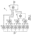
- Figure 1 illustrates a high level block diagram of the leading one bit indicator found in the AMD 29050. (Note: a leading one indicator may easily be converted to determine a number of leading zeros by inverting each of the data input signal bits prior to its reception by the leading one indicator).
- the AMD 29050 56 bit counter receives a 56 bit number with the last bit, bit 0, being the least significant bit and the first bit, bit 55, being the most significant bit.
- the 8 bit counter logic 112 receives the most significant group of bits 48-55
- 8 bit counter logic 110 receives the second most significant group of bits 40-47
- 8 bit counter logic 108 receives the third most significant group of bits 40-47
- 8 bit counter logic 108 receives the fourth most significant group of bits 32-39
- 8 bit counter logic 106 receives the fifth most significant group of bits 24-21
- 8 bit counter logic 104 receives the sixth most significant group of bits 16-23
- 8 bit counter logic 102 receives the seventh most significant group of bits 8-15
- 8 bit counter logic 100 receives least significant group of bits 0-7.
- Each 8 bit counter logic provides two outputs. The first output is a 3 bit output representing the number of leading ones in the 8 bit data input signal of the 8 bit counter logic.
- the second output of the 8 bit counter logic is a 2 bit signal representing the presence of a zero in the least significant 4 bits and the presence of a zero in the most significant 4 bits.
- the 56 bit counter logic 122 receives the output of 8 bit counter logic 100.
- the 16 bit counter logic 114 receives the outputs of 8 bit counter logic 102 and 104.
- the 56 bit counter logic 122 receives two outputs from 16 bit counter logic 114.
- the first output of 16 bit counter logic 114 is a 4 bit number representing the number of leading ones in the data input signal to 16 bit counter logic 114.
- the second output is a 2 bit number that represents the presence or the absence of a zero in bits 8-23.
- Sixteen bit counter logic 114 first determines the presence of a zero in the most significant 8 bits 16-23. If a zero is present, the circuit determines only the number of zeros in the most significant 8 bits. If the most significant 8 bits contained all ones, the output would correspond to the 8 ones in the most significant 8 bits plus the number of ones in the least significant 8 bits. The output is then received by the 56 bit counter logic 122.
- Sixteen bit counter logic 116 functions similarly to 16 bit counter logic 114 except that 16 bit counter logic 116 operates on bits 24-39 and 16 bit counter logic 118 operates on bits 48-55.
- Sixteen bit counter logic 116 and 16 bit counter logic 118 have outputs that are received by 32 bit counter logic 120. Thirty-two bit counter logic 120 determines the number of ones in the two 16 bit counter logics 116 and 118. If the most significant 16 bits, bits 40-55, contain a zero, the output of 32 bit counter logic will represent the number of ones present in bits 40-55. If bits 40-55 contain all ones, the output of 32 bit counter logic 120 will reflect the number of ones present in bits 24-55. Thirty-two bit counter logic 120 has a second output indicating whether or not a zero is present in bits 40-55 and whether or not a zero is present in bits 24-39.
- Fifty-six bit counter logic 122 contains the final output which represents the number of leading ones in the original 56 bit data input signal. Fifty-six bit counter logic 122 operates by detecting the presence of a zero in the most significant 32 bits. If a zero is detected, the number of ones received from 32 bit counter logic 120 are provided to an output. This result represents the correct number of leading ones in the original 56 bit data input signal. If the most significant 32 bits contain all ones, 56 bit counter logic 122 then analyzes the next 16 bits, bits 8-23, and detects the presence of a zero. If a zero is present, the output of 56 bit counter logic 122 represents the most significant 32 bits containing ones exclusively and the number of leading ones in the next 16 bits, bits 8-23.
- the 56 bit counter logic 122 subsequently analyzes the 8 bit counter logic 100 output only if the most significant 48 bits contained all ones. If the most significant 48 bits contained all ones, the output of 56 bit counter logic 122 would reflect the number of leading ones in the most significant 48 bits containing ones exclusively and the number of leading ones in the least significant 8 bits. Fifty-six bit counter logic 122 has a second output that represents the presence of a zero anywhere in the original 56 bit data input signal.
- a disadvantage of the discussed prior art is the complex implementation of multiple stages necessary to determine the number of leading count bits present in a data input signal. Further, complex implementation results in a slower device speed due to propagation delays from a larger number of logic stages.
- a first aspect of the present invention concerns a leading digit indicator for determining a number of leading count values in a data input signal.
- a leading digit indicator pertains to a device used to determine a number of particular count digits in a data signal that lead or precede a non-count digit.
- a count digit is a digit whose value it is desirable to count.
- a non-count digit is a digit whose value it is not desirable to count.
- Leading count digits are the most significant digits in a data input signal, having any number of digits, that precede (or are more significant than) the most significant non-count digit.
- the data input signal has X groups of M digits with each digit having N possible values. The N possible values may be count values and non-count values.
- the leading digit indicator includes a first input to receive a first data input signal.
- the first data input signal is indicative of a number of most significant groups of M digits leading a most significant non-count group.
- the first data input signal may be provided by a counter or counter-detector.
- the most significant non-count group is a most significant group of M bits to have a non-count digit, where a non-count digit is a digit with a non-count value.
- the leading digit indicator further includes a second input to receive a second data input signal.
- the second data input signal is indicative of a number of leading count digits in the first non-count group, where a count digit is a digit with a count value.
- the second data input signal may be provided by a counter or counter-detector.
- the count and non-count values may include a two values such as a zero and a one in a binary data signal or may include groups of values in a data input signal possessing a multiplicity of values.
- the leading digit indicator further includes a concatenator, coupled to the first and second inputs, to concatenate the first data input signal and the second data input signal to form a concatenation representing the number of leading count digits in the X groups of M digits in the data input signal.
- the leading digit indicator of the present invention is particular in that the data input signal includes R most significant digits in addition to the X groups of M bits, and includes a third input to receive a third data input signal, adder circuitry, and multiplexer circuitry, the third data input signal indicates the presence and location of a non-count digit in the R most significant digits, and is provided by counter-detector, the adder circuitry is coupled to the concatenator circuitry and adds R to the concatenation to form a concatenation plus R , the adder circuitry further has an output to communicate the concatenation plus R , the multiplexer circuitry, coupled to the adder output to receive the concatenation plus R and the third data input signal, includes an output to communicate the concatenation plus R when the third input data signal indicates the absence of a non-count digit in the R most significant digits and to communicate the number of leading count digits in the R most significant digits when the third input signal indicates the presence and location of
- a second aspect of the invention is a method as defined in independent claim 11. Further embodiments of the invention are specified in the appended dependent claims.
- Figure 1 illustrates a block diagram of the prior art Advanced Micro Devices 29050 Leading One Indicator.
- Figure 2 illustrates a block diagram of a 67 bit Leading Zero Indicator.
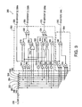
- Figure 3 illustrates a schematic diagram of an 8 bit COUNTER-DETECTOR employed by the 67 bit Leading Zero Indicator.
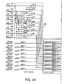
- Figure 4 illustrates a schematic diagram of a DECODER employed by the 67 bit Leading Zero Indicator.
- Figure 5 illustrates a schematic diagram of an ADDER-CONCATENATOR unit employed by the 67 bit Leading Zero Indicator.
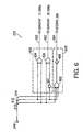
- Figure 6 illustrates a schematic diagram of a 4 bit COUNTER-DETECTOR employed by the 67 bit Leading Zero Indicator.
- Figure 7 illustrates a schematic diagram of a MULTIPLEXER employed by the 67 bit Leading Zero Indicator.
- Figure 8 illustrates a schematic diagram of a 64 bit Leading Zero Indicator.
- Figure 9 illustrates a schematic diagram of a CONCATENATOR-MULTIPLEXER employed by the 64 bit Leading Zero Indicator.
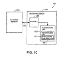
- Figure 10 illustrates a block diagram of a computer system.
- the 67 bit Leading Zero Indicator 200 may be used, for example, in a Renormalizing unit 1002 within a floating point unit 1004 which is part of a computer system 1014.
- a Renormalizing unit is part of a floating point unit.
- various floating point units are well known in the art, and include the Floating Point Unit in U.S. Patent Number 5,058,048,
- the Floating Point Unit 1004 may be used, for example, separately from or, as shown, integrated with a Microprocessor 1006.
- a Microprocessor 1006 One suitable integration of a floating point unit with a superscalar microprocessor is disclosed in EP-A-0 651 321.
- the interface 1008 of microprocessor 1006 is connected via bus 1010 to external memory 1012.
- the computer system 1014 typically includes such other components as a keyboard and display (not shown).
- Figure 2 illustrates a block diagram of a 67 bit Leading Zero Indicator.
- the 67 bit Leading Zero Indicator 200 incorporates enumerator circuit 227, ADDER-CONCATENATOR 222 and MULTIPLEXER 224.
- Enumerator circuit 227 includes counter circuit 226 and 4 bit COUNTER-DETECTOR 216.
- Counter circuit 226 contains nine 8 bit COUNTER-DETECTORS 201-214 and 218 and DECODER 220.
- the 67 bit Leading Zero Indicator receives a binary data input signal obtained from floating point data stored in the external memory 1012 of Figure 10. Each bit of the binary data input signal possesses one of two values.
- Enumerator circuit 227 has individual inputs for receiving each bit of a binary data input signal in parallel, although it will be appreciated that the circuit could easily be modified to receive each bit serially.
- the two values may be denoted as zeros and ones with a zero representing a reference voltage level, e.g. 0 Volts, and a one representing a different voltage level, e.g. +5 Volts (although other voltage levels such as +3 Volts may be used).
- a binary leading zero indicator determines the number of leading zeros, i.e. the number of zeros in the most significant positions of the data input signal that precede a one, and if a one is not present in the data input signal, the number of zeros in the data input signal.
- a zero symbolizes a "count bit” and a one symbolizes a "non-count bit.”
- a "count bit” denotes a value that is to be counted by a leading bit indicator
- a "non-count bit” denotes a value that is not to be counted by a leading bit indicator.
- enumerator circuit 227 receives a 67 bit data input signal 230 in parallel and segments the 67 bit data input signal 230, by routing data signal input lines 221a-221j to the counter detectors 201-216, respectively, into a most significant group of 3 bits and 8 groups of 8 bits.
- Data signal input lines 221a-221h each consist of 8 separate conductors, and data signal line 221j consists of 3 separate conductors.
- the 4-bit COUNTER-DETECTOR 216 and counter circuit 226 receive portions of the segmented 67 bit data input signal 230.
- the 4 bit COUNTER-DETECTOR 216 receives the most significant group of bits (66:64) 246, 8 bit COUNTER-DETECTOR 214 receives the second most significant group of bits (63:56) 244, 8 bit COUNTER-DETECTOR 212 receives the third most significant group of bits (55:48) 242, 8 bit COUNTER-DETECTOR 210 receives the fourth most significant group of bits (47:40) 240, 8 bit COUNTER-DETECTOR 208 receives the fifth most significant group of bits (39:32) 238, 8 bit COUNTER-DETECTOR 206 receives the sixth most significant group of bits (31:24) 236, 8 bit COUNTER-DETECTOR 204 receives the seventh most significant group of bits (23:16) 234, 8 bit COUNTER-DETECTOR 201 receives the eighth most significant group of bits (15:8) 232, 8 bit COUNTER-DETECTOR 201 receives the least significant group of bits (7:0) 231.
- the 67 bit data input signal 230 was purposefully segmented into the most significant group of 3 bits and a least significant group of 64 bits. The least significant group of 64 bits was further segmented into 8 groups of 8 bits. Each 8 bit group is received by an 8 bit COUNTER-DETECTOR 201-214 which provides a 3 bit counter output signal and a one bit detector output signal which, when taken as a whole, indicate the number of leading zeros in the 8 bit data input signal.
- the number of data input signal bits to each COUNTER-DETECTOR is directly related to the number of possible values in the data input signal and the number of 8 bit COUNTER-DETECTOR counter output signal bits.
- "digit" is used to represent a single place in a data input signal with each digit capable of having any of a desired number of values such as zero, one, two, three, four, and so forth, with zeros and ones being used in a binary digit system.
- FIG 3 illustrates the schematic of 8 bit COUNTER-DETECTOR 300 which schematically represents all of the 8 bit COUNTER-DETECTORS 201-214 and 218.
- the circuits illustrated in Figure 3 as well as those in Figures 2 and Figures 4-9 are fabricated in complementary metal oxide semiconductor.
- One suitable implementation of 8 bit COUNTER-DETECTOR 300 uses an input with data signal input lines 346-360, counter circuitry 362, and detector circuitry 364. Note that 8 bit COUNTER-DETECTOR 300 may be considered as a separate counter 362 combined with a separate detector 364.
- the counter circuitry 362 uses NOR gates 301 and 302, INVERTERS 304-310, OR gate 316, NAND gates 318-328, outputs 366-370, and NAND gates 332-334 connected as shown in Figure 3 to provide a 3 bit counter output signal, ZEROCNT (2) 338a, ZEROCNT (1) 338b, and ZEROCNT (0) 338c, which indicates the number of leading zeros in the 8 bit data input signal 336.
- the detector circuitry 364 uses NOR gates 312 and 314, output 372, and NAND gate 330 connected as shown in Figure 3 to detect the presence of a one in the 8 bit data input signal 336 and provide a single bit output GTZERO 344 indicating the presence and absence of a detected one.
- an 8 bit COUNTER-DETECTOR 300 determines the number of leading zeros in its respective 8 bit data input signal.
- Eight bit COUNTER-DETECTOR 300 receives an 8 bit data input signal 336 with each bit received and conducted sequentially on an input with data signal input lines 346-360 with input line 346 receiving the most significant bit. (Note: "sequentially" in the description of the preferred embodiments connotes location and does not connote a reference to time).
- Input lines 346-360 may collectively represent each of the data signal input lines 221a-221h.
- the 8 bit COUNTER-DETECTOR 300 has a 3 bit counter output signal, ZEROCNT (2) 338a, ZEROCNT (1) 338b, and ZEROCNT (0) 338c, representing the number of leading zeros in its 8 bit data input signal 336 when at least one of the data signal inputs 346-360 conducts a one. By ascertaining the number of leading zeros, the location of the most significant one is determined.
- the 3 bit counter output signal is conducted by an output with output signal lines 366-370.
- ZEROCNT (2) 338a represents the most significant bit
- ZEROCNT (1) 338b represents the next most significant bit
- ZEROCNT (0) 338c represents the least significant bit of the 3 bit output of 8 bit COUNTER-DETECTOR 300.
- the 8 bit COUNTER-DETECTOR 300 also contains a single bit detector output signal, GTZERO 344, which represents the presence of a one in the 8 bit data input signal when a one is present and the absence of a one in the 8 bit data input signal when a one is absent.
- the single bit detector output signal is conducted by output 372. If GTZERO 344 equals one (first state), one of the 8 bits received by the 8 bit COUNTER-DETECTOR 300 equals one. If GTZERO 344 equals zero (second state), all 8 bits of the data input signal are zeros.
- the 3 bit counter output signal and the one bit detector output signal indicate the number of zeros in the 8 bit data input signal.
- Figure 4 illustrates a schematic diagram of DECODER 220.
- the DECODER 220 is connected to COUNTER-DETECTORS 201-214.
- One suitable implementation of DECODER 220 connects NOR gates 401-410, INVERTER 412, and NAND gates 414-426 to form circuit 466 as shown in Figure 4.
- Circuit 466 is connected to an input with data signal input lines 470-484.
- DECODER 220 is further implemented by connecting identical circuits 468a, 468b, and 468c to circuit 466 and data inputs 486(Y)-499(Y).
- circuits 468a, 468b, and 468c are represented schematically by a single circuit implemented by connecting INVERTERS 428(Y) - 442(Y), NOR gates 444(Y) - 458(Y), NOR gates 460(Y) and 462(Y), and NAND gate 464(Y) as shown in Figure 4.
- Note the legend "FOR Y a to c" in the boxes surrounding circuits 468a, 468b, and 468c.
- circuit 468a when “Y” is substituted with “a”, circuit 468a is obtained, when “Y” is substituted with “b”, circuit 468b is obtained, and when "Y” is substituted with “c”, circuit 468c is obtained (note: the “(2:0)” has been omitted from the ZEROCNT 280(Y) - 287(Y) symbology within the boxes surrounding circuits 468a, 468b, and 468c).
- circuit 466 receives input signals GTZERO 270-277 conducted by data signal input lines 470-484. (Note: For clarity, elements present in multiple figures retain the same identifying numerals throughout all figures). Circuit 466 provides an 8 bit output with a single bit being a zero corresponding to the GTZERO output signal of the most significant of the 8 bit COUNTER-DETECTORS 201-214 to contain a one in its respective 8 bit data signal input with the other seven output bits of circuit 466 being ones. The most significant of-the 8 bit COUNTER-DETECTORS 201-214 to contain a one in its respective 8 bit data input signal may be referred to as a "non-count group" due to the presence of a non-count value in its respective 8 bit data input signal.
- circuits 468a, 468b, and 468c receive data signals from circuit 466 and data input signals ZEROCNT (2:0) 280a,b,c-287a,b,c.
- Data input signals ZEROCNT (2:0) 280a,b,c-287a,b,c are conducted by inputs 486(Y)-499(Y).
- Circuit 468a receives ZEROCNT (2) 280a-287a, the most significant bits of ZEROCNT (2:0) 280a,b,c - 287a,b,c, respectively.
- ZEROCNT (2:0) 280a,b,c conveniently and concisely symbolizes ZEROCNT (2) 280a, ZEROCNT (1) 280b, and ZEROCNT (0) 280c.
- ZEROCNT (2) 280a symbolizes bit 2
- ZEROCNT (1) 280b symbolizes bit 1
- ZEROCNT (0) 280a symbolizes bit 0, the least significant bit of ZEROCNT (2:0) 280a,b,c).
- Circuit 468b receives ZEROCNT (1) 280b-287b, the next most significant bits of ZEROCNT (2:0) 280a,b,c - 287a,b,c, respectively.
- Circuit 468c receives ZEROCNT (0) 280a,b,c-287a,b,c, the least significant bits of ZEROCNT (2:0) 280a,b,c - 287a,b,c, respectively.
- Circuits 468a, 468b, and 468c each receive identical data from circuit 466. Circuits 468a, 468b, and 468c provide the 3 bit data output signal ZEROCNT (2:0) 290 a,b,c, respectively.
- Circuits 468a, 468b, and 468c receive the outputs of circuit 466 and ZEROCNT (2) 280a - 287a, ZEROCNT (1) 280b - 287b, and ZEROCNT (0) 280c - 287c, respectively, from 8 bit COUNTER-DETECTORs 201-214 as inputs.
- the bit of circuit 466 equaling zero enables circuits 468a, 468b,and 468c to communicate the ZEROCNT (2:0), corresponding to the NAND gate connected to the single zero output of circuit 466, to the output data signal lines 465(Y) which conducts data signal output ZEROCNT (2:0) 290a,b,c. If GTZERO 270-277 all equal zero corresponding to 67 bit data input signal containing all zeros, i.e. 67 leading zeros, then ZEROCNT (2:0) 290a,b,c, is 000 2 .
- the second outputs, GTZERO 270-277, of the 8 bit COUNTER-DETECTORS 201-214 are additionally connected to 8 bit COUNTER-DETECTOR 218 and provide an 8 bit data input signal to 8 bit COUNTER-DETECTOR 218.
- the schematic diagram Figure 3 which illustrates 8 bit COUNTER-DETECTORS 201-214 also illustrates 8 bit COUNTER-DETECTOR 218.
- Three bit counter output signal ZEROCNT (2:0) 292a,b,c represents the number of leading zeros in the 8 bit data input signal of 8 bit COUNTER-DETECTOR 218 if a one is present in the data input signal.
- One bit detector output signal GTZERO 294 represents the presence or absence of a one in the 8 bit data input signal.
- the 3 bit counter output signal and the one bit detector output signal indicate the number of zeros in the 8 bit data input signal regardless of the presence of a one in the 8 bit data input signal.
- the 8 bit COUNTER-DETECTORS 218 could be easily modified individually or in any combination to provide a 4 bit counter output signal representing the number of leading zeros in the 8 bit data input signal regardless of the presence of a one in the 8 bit data input signal.
- inverter 901 and circuits 910b, 910c, and 910d are appropriately connected to GTZERO 344, ZEROCNT (2) 338a, ZEROCNT (1) 338b, and ZEROCNT (0) 338c, a 4 bit counter output signal capable of representing the number of leading zeros in an 8 bit data input signal containing all zeros will be provided in conventional binary format i.e. with bit n representing 2 n in base 10.
- each increment from 001 2 to 111 2 of ZEROCNT (2:0) 292a,b,c represents an entire group of 8 zeros from each of the most significant of 8 bit COUNTER-DETECTORS in Figure 2 possessing all zeros in their data input signal bits preceding the most significant 8 bit COUNTER-DETECTOR in Figure 2 possessing a one in its data input signal.
- the most significant groups of bits having an absence of non-count values that precede the most significant group of bits having a non-count value (“non-count" group) may be referred to as the "count group" or the number of most significant groups of 8 bits leading a most significant non-count group.
- the count group or the number of most significant groups of 8 bits leading a most significant non-count group.
- ZEROCNT (2:0) 292a would equal 100 2 or 4 10 which represents the number of most significant count groups.
- FIG. 5 illustrates a schematic diagram of ADDER-CONCATENATOR 222.
- ADDER-CONCATENATOR 222 is connected to 8 bit COUNTER-DETECTOR 218 and DECODER 220.
- one suitable implementation of ADDER-CONCATENATOR 222 appropriately connects an input with data input signal lines 540-550, an output with data output signal lines 552-564, INVERTERS 501 and 502, NAND gates 504-510, INVERTERS 512-514, NAND gates 516-520, NAND gates 522 and 524, INVERTER 526 and 528, and EXCLUSIVE OR gates 530-538 to obtain adder-concatenator circuitry.
- Adder-concatenator 222 may be divided into concatenator circuitry 575 and adder circuitry 577.
- ADDER-CONCATENATOR 222 performs the function of concatenating ZEROCNT (2:0) 290a,b,c to ZEROCNT (2:0) 292a,b,c with concatenator circuitry 575 and adding 11 2 to the concatenation to obtain ADDER-CONCATENATOR's 222 seven bit data output signal ALCNT (6:0) 297a,b,c,d,e,f,g with adder circuitry 577.
- ADDER-CONCATENATOR 222 receives the data output signals of 8 bit DECODER 220 and COUNTER-DETECTOR 218, ZEROCNT 290a,b,c and ZEROCNT 292a,b,c, respectively.
- An input with data input signal lines 540-544 and 546-550 conducts data output signals ZEROCNT 290a,b,c and ZEROCNT 292a,b,c, respectively.
- Concatenator circuitry 575 concatenates data output signals ZEROCNT (2:0) 292a,b,c and ZEROCNT (2:0) 290a,b,c by taking the two sets of three signal lines conducting data output signals ZEROCNT (2:0) 292a,b,c and ZEROCNT (2:0) 290a,b,c and combining them into one group of six signal lines 540-550.
- Data input signal line 550 conducts the most significant bit of ZEROCNT (2:0) 292a,b,c, ZEROCNT (2) 292a.
- Data input signal line 544 conducts the most significant bit of data input signal ZEROCNT (2:0) 290a,b,c, ZEROCNT (2) 290a.
- An output with data output signal lines 552-564 conducts data output signal ALCNT (6:0) 297a,b,c,d,e,f,g with data output signal line 552 conducting the most significant bit.
- the concatenation of ZEROCNT (2:0) 290a,b,c to ZEROCNT (2:0) 292a,b,c forms a 6 bit number that represents the number of leading zeros in the least significant 64 bits of the 67 bit data input signal 230 when a single one bit is present in the least significant 64 bits.
- ADDER-CONCATENATOR 222 could be modified to concatenate the 4 bit counter output signal of 8 bit COUNTER-DETECTOR 218 with the output of DECODER 220 and adding 11 2 to the concatenation thus providing a 7 bit output representing the number of leading zeros in the 67 bits when the 3 most significant bits 246 contain all zeros regardless of the presence of a one in the least significant 64 bits).
- every increment of 8 bit COUNTER-DETECTOR 218 represents a group of 8 zeros. Therefore, if ZEROCNT (2:0) 292a,b,c is initially placed in the three most significant positions of a 6 bit data signal (such as the one conducted by concatenator circuitry's 575 data input signal lines 540-550), the most significant 3 bits of the 6 bit data output signal will represent the number of most significant zeros in the 64 bit data input signal of counter circuit 226 preceding the most significant first group of eight bits from inputs 231-244 to contain a one. When the least significant 3 bits of the 6 bit data output signal represent the output of DECODER 220, the 6 bit data output signal represents the number of leading zeros in the 64 bit data input signal of counter circuit 226.
- ADDER-CONCATENATOR 222 incorporates this principle by concatenating ZEROCNT (2:0) 290a,b,c with ZEROCNT (2:0) 292a,b,c to form a 6 bit number.
- ZEROCNT (2:0) 290a,b,c with ZEROCNT (2:0) 292a,b,c to form a 6 bit number.
- 11 2 is added to the 6 bit concatenation. Therefore, if the 3 most significant bits 246 of 67 bit data input signal 230 are all zeros, the output of ADDER-CONCATENATOR 222 represents the number of leading zeros in the 67 bit data input signal 230 when a one is present in the input signal.
- Figure 6 illustrates one embodiment of the 4 bit COUNTER-DETECTOR 216.
- Four bit COUNTER-DETECTOR 300 receives a 3 bit data input signal 246 with each bit present sequentially on an input with data input signal lines 610-614 with input signal line 610 receiving the most significant bit.
- 4 bit COUNTER-DETECTOR 216 receives the 3 most significant bits of 67 bit data input signal 230.
- 4 bit COUNTER-DETECTOR 216 may be considered as a separate counter 616 combined with a separate detector 618.
- Four bit COUNTER-DETECTOR 216 employs counter circuitry 616 and detector circuitry 618.
- Counter circuitry may be implemented by appropriately connecting INVERTER 601 and NOR gates 604-606, outputs 620-624, and INVERTER 608 as shown in Figure 6 to count the number of leading count values, zeros, conducted by data input signal lines 610-614.
- Detector 618 circuitry may be implemented by appropriately connecting NOR gate and INVERTER 608 as shown in Figure 6 to detect the presence and absence of a non-count value, one, conducted by any of the data input signal lines 610-614.
- the 4 bit COUNTER-DETECTOR 216 has a two bit counter output signal, ZEROCNT (1) 296a, the most significant bit, and ZEROCNT (0) 296b the least significant bit, and a single bit detector output signal, GTZERO 295.
- 4 bit COUNTER-DETECTOR 216 determines the number of leading zeros in its 3 bit data input signal 246.
- Data input signal lines 610-614 conduct 3 bit data input signal 246 with data input signal line 610 conducting the most significant bit.
- the 4 bit COUNTER-DETECTOR 216 provides a 2 bit data output signal, ZEROCNT (1) 296a and ZEROCNT (0) 296b, conducted to an output with data output signal lines 620-622, respectively.
- Data output signals ZEROCNT (1) 296a and ZEROCNT (0) 296b represent the number of leading zeros in 3 bit data input signal 246, when a one is present in the 3 bit data input signal 246.
- the 4 bit COUNTER-DETECTOR 216 also provides a single bit data output signal, GTZERO 295, conducted to the output by data output signal line 624.
- Data output signal, GTZERO 295 represents the presence and absence of a one in the data input signal 246.
- Output 624 conducts detector output signal GTZERO 295.
- GTZERO 295 has two states where the first state represents the presence of a one in the data input signal 246 and a second state that represents the absence of a one in the data input signal 246. If GTZERO 295 equals one (first state), one of the 3 bits received by the 4 bit COUNTER-DETECTOR 300 in Figure equals one. If GTZERO 295 equals zero (second state), all 3 bits of the data input signal are zero. The 2 bit counter output signal and the one bit detector output signal indicate the number of leading zeros in the 3 bit data input signal 246.
- FIG. 7 illustrates the schematic diagram of MULTIPLEXER 224.
- MULTIPLEXER 224 appropriately connects INVERTER 701, NOR gates 702 and 704, data output signal lines, 734, 730(X), and 732(Y), and data input signal lines 720 and 722.
- MULTIPLEXER 224 is further implemented by connecting identical circuits 718a, 718b, 718c, 718d, and 718e to NOR gate 704, an output with data output signal lines 732(Y), and an input with data input signal lines 728(Y), for Y equal to "a to e".
- MULTIPLEXER 224 is further implemented by connecting identical circuits 718f and 718g to NOR gate 704, an output with data output signal lines 730(X), an input with data input signal lines 724(X), and inputs 726(X) for X equal to "f to g".
- the implementations result in the multiplexer circuitry shown in Figure 7.
- circuit 718a when “Y” is substituted with “a”, circuit 718a is obtained, when “Y” is substituted with “b”, circuit 718b is obtained, when “Y” is substituted with “c”, circuit 718c is obtained, when “Y” is substituted with “d”, circuit 718d is obtained, and when "Y" is substituted with “e”, circuit 718e is obtained (note: the “(1:0)” has been omitted from the ZEROCNT 296(X) and the ALCNT 297(Y) symbology within the boxes surrounding circuits 718a, 718b, 718c, 718d, and 718e, 718f, and 718g).
- Circuits 718a, 718b, 718c, 718d, and 718e provide the most significant bit through the fifth most significant bit, (ZCNT (6:2) 299a,b,c,d,e) respectively, of data output signal ZCNT (6:0) 299a,b,c,d,e,f,g.
- Circuits 718f and 718g provide the sixth most significant and least significant bits, (ZCNT (1:0) 299f,g) respectively, of data output signal ZCNT (6:0) 299a,b,c,d,e,f,g.
- MULTIPLEXER 224 receives 4 data input signals.
- the data input signals are GTZERO 294, GTZERO 295, ZEROCNT (1:0) 296a, and ALCNT (6:0) 297a,b,c,d,e,f,g.
- An input with data input signal lines 720 and 722 conducts detector data input signals GTZERO 294 and GTZERO 295, respectively.
- ALCNT (6:0) 297a,b,c,d,e,f,g is segmented such that an input with data input signal lines 728(Y) and 724(X) conducts data input signals ALCNT (6:2) 297a,b,c,d,e (ALCNT 297(Y)) and ALCNT (1:0) 297f,g (ALCNT 297(X)), respectively.
- An input with data input signal lines 726(X) conducts data input signals ZEROCNT (1:0) 296a,b (ZEROCNT 296(X)), respectively.
- MULTIPLEXER 224 provides the 7 bit data output signal ZCNT (6:0) 299a,b,c,d,e,f,g and one bit data output signal PSZERO 298 indicating the number of leading zeros in the original 67 bit data input signal.
- An output with data signal output lines 732(Y) and 730(X) conducts data output signals ZCNT (6:2) 299a,b,c,d,e (ZCNT 299(Y)) and ZCNT (1:0) 299f,g (ZCNT 299(X)), respectively.
- An output with data output signal line 734 conducts data output signal PSZERO 298.
- Circuits 716a, 716b, 718a, 718b, 718c, 718d, and 718e allow ALCNT (6:0) 297a,b,c,d,e,f,g to communicate to the output of MULTIPLEXER 224 (represented by 7 bit data output signal ZCNT (6:0) 299a,b,c,d,e,f,g) if GTZERO 294 equals 1 2 and GTZERO 295 equals 0 2 which indicates-there are no ones in the data input signal 246 of 4 bit COUNTER-DETECTOR 216.
- a single bit data output signal PSZERO 298 of MULTIPLEXER 224 equals one and ZCNT (6:0) 299a,b,c,d,e,f,g equals 0000000 2 which indicates that all 67 bits of input signal 230 are zero.
- PSZERO 298 equals zero if there is a one present in any of the 67 bits of the original 67 bit data input signal 230.
- GTZERO 294'and GTZERO 295 are instrumental in allowing MULTIPLEXER 224 to select the correct output to indicate the number of leading zeros in the 67 bit data input signal 230.
- each bit of 67 bit data input signal 230 is capable of possessing two possible values denoted as ones and zeros. It will be further assumed that leading zeros are to be determined, therefore, zeros are denoted here as "count bits” and ones are "non-count bits.”
- count bits zeros are denoted here as "count bits” and ones are "non-count bits.”
- COUNTER-DETECTORS 216-201 receive data input signal 246 which contains the three most significant bits, 000 (group A).
- the most significant 8 bit COUNTER-DETECTOR 214 receives data input signal 244 which contains the most significant group of 8 bits, 00000000 (group B).
- the second most significant 8 bit COUNTER-DETECTOR 212 receives data input signal 242 which contains the second most significant group of 8 bits, 00000000 (group C).
- the third most significant 8 bit COUNTER-DETECTOR 210 receives data input signal 240 which contains the third most significant group of 8 bits, 00000000 (group D).
- the fourth most significant 8 bit COUNTER-DETECTOR 208 receives data input signal 238 which contains the fourth most significant group of 8 bits, 00000010 (group E).
- the fifth most significant 8 bit COUNTER-DETECTOR 206 receives data input signal 236 which contains the fifth most significant group of 8 bits, 11110000 (group F).
- the sixth most significant 8 bit COUNTER-DETECTOR 201 receives data input signal 234 which contains the sixth most significant group of 8 bits, 00101011 (group G).
- the seventh most significant 8 bit COUNTER-DETECTOR 204 receives data input signal 232 which contains the seventh most significant group of 8 bits, 00000000 (group H).
- the least significant 8 bit COUNTER-DETECTOR 202 receives data input signal 231 which contains the least significant group of 8 bits, 00000001 (group J).
- the 8 bit COUNTER-DETECTOR 208 is, therefore, the most significant 8 bit COUNTER-DETECTOR with a one in its 8 bit data input signal, i.e. the most significant non-count group.
- the 3 bits represented by ZEROCNT (2:0) also indicate the location of the first non-count bit or one i.e. the seventh position.
- GTZERO 270-277 is received sequentially by 8 bit COUNTER-DETECTOR 218.
- Figure 8 illustrates a block diagram of a 64 bit Leading Zero Indicator 800.
- the 64 bit Leading Zero Indicator 800 is designed to determine the number of leading zeros in a 64 bit data input signal 830 received in parallel and consists of counter circuit 826 and CONCATENATOR-MULTIPLEXER 824.
- Counter circuit 826 is identical to counter circuit 226.
- the difference between the 64 bit Leading Zero Indicator of Figure 8 and the 67 bit Leading Zero Indicator of Figure 2 is that the 4 bit COUNTER-DETECTOR 216 is not needed and ADDER-CONCATENATOR 222 and MULTIPLEXER 224 are replaced by CONCATENATOR-MULTIPLEXER 824.
- CONCATENATOR-MULTIPLEXER 824 includes an input with input data signal lines 914, 916(X), and 918(Y) for receiving three data input signals, GTZERO 894, ZEROCNT (2:0) 890e,f,g and ZEROCNT (2:0) 892b,c,d.
- GTZERO 894 is a single bit detector data input signal from 8 bit COUNTER-DETECTOR 818 representing the presence or absence of a one in 8 bit COUNTER-DETECTOR 818's data input signal.
- ZEROCNT (2:0) 890e,f,g is a 3 bit counter data input signal from DECODER 820 representing the number of leading zeros in the most significant 8 bit COUNTER-DETECTOR in Figure 8 to contain a one in its data input signal.
- ZEROCNT (2:0) 892b,c,d is a 3 bit data input signal from 8 bit COUNTER-DETECTOR 818 representing the number of 8 bit groups of zeros contained in the 64 bit data input signal 830 before a one is detected.
- CONCATENATOR-MULTIPLEXER 824 provides a seven bit data output signal ZCNT (6:0) 899a,b,c,d,e,f representing the number of leading zeros in the original 64 bit data input signal.
- FIG. 9 illustrates the schematic diagram of CONCATENATOR-MULTIPLEXER 824 constituting concatenator-multiplexer circuitry.
- One implementation of CONCATENATOR-MULTIPLEXER 824 connects INVERTER 901, identical circuits 910b, 910c, and 910d, an input with data input signal line 914, an output with data output signal line 924, and identical circuits 912e, 912f, and 912g as shown in Figure 9.
- CONCATENATOR-MULTIPLEXER 824 is further implemented by appropriately connecting circuits 910b, 910c, and 910d to data input signal line 914, the input with data input signal lines 916(X), and the output with data output signal lines 920(X) as shown in Figure 9.
- Data input signal line 914 conducts detector data input signal GTZERO 894, and data input signal lines 916(X) conduct data input signal ZEROCNT (2:0) 892b,c,d.
- data output signal lines 920(X) conduct data output signal ZCNT (5:3) 899b,c,d.
- CONCATENATOR-MULTIPLEXER 824 is further implemented by appropriately connecting circuits 912e, 912f, and 912g to data input signal line 914, the input with data input signal lines 918(Y), and the output with data output signal lines 922(Y) as shown in Figure 9.
- Data input signal lines 918(Y) conduct data input signal ZEROCNT (2:0) 890e,f,g, and data output signal lines 922(Y) conduct data output signal ZCNT (2:0) 899e,f,g.
- circuits 910b, 910c, and 910d are represented schematically by a single circuit implemented by appropriately connecting NAND gates 902(X) and INVERTERS 904(X).
- Note the legend "FOR Y b to d” in the boxes surrounding circuits 910b, 910c, and 910d.
- the legend denotes that when “Y” is substituted with “b”, circuit 910b is obtained, when “Y” is substituted with "c”, circuit 910c is obtained, and when "Y” is substituted with "d”, circuit 910d is obtained (note: the "(2:0)" has been omitted from the ZEROCNT 892(Y) symbology within the boxes surrounding circuits 910b, 910c, and 910d).
- circuits 912e, 912f, and 912g appropriately connects NAND gates 906(Y) and INVERTERS 908(Y) as shown in Figure 9.
- Note the legend "FOR Y e to g" in the boxes surrounding circuits 912e, 912f, and 912g.
- the legend denotes that when “Y” is substituted with “e”, circuit 912e is obtained, when “Y” is substituted with "f", circuit 912f is obtained, and when "Y” is substituted with "g”, circuit 912g is obtained (note: the "(2:0)" has been omitted from the ZEROCNT 890(Y) symbology within the boxes surrounding circuits 912e, 912f, and 912g).
- INVERTER 901 provides the most significant bit, ZCNT (6) 899a, of data output signal ZCNT (6:0) 899a,b,c,d,e,f,g.
- Circuits 910b, 910c and 910d provide the second, third, and fourth most significant bits, (ZCNT (5:3) 899b,c,d) respectively, of data output signal ZCNT (6:0) 899a,b,c,d,e,f,g.
- Circuits 912e, 912f, and 912g provide the fifth, sixth, and least most significant bits, (ZCNT (2:0) 899e,f,g) respectively, of data output signal ZCNT (6:0) 899a,b,c,d,e,f,g.
- Concatenator-multiplexer 824 may be divided into concatenator circuitry 951 and multiplexer circuitry 953.
- CONCATENATOR-MULTIPLEXER 824 performs the function of concatenating data signals ZEROCNT (2:0) 892b,c,d and ZEROCNT (2:0) 890e,f,g with concatenator circuitry 951 and selecting the output correctly representing the number of leading zeros in the 64 bit data input signal 830.
- Concatenator circuitry 951 concatenates data output signals ZEROCNT (2:0) 892a,b,c and ZEROCNT (2:0) 890a,b,c by taking the two sets of three signal lines conducting data output signals ZEROCNT (2:0) 292a,b,c and ZEROCNT (2:0) 290a,b,c and combining them into one group of six signal lines 916(X) and 918(Y).
- CONCATENATOR-MULTIPLEXER 824 receives data input signals GTZERO 894, ZEROCNT 892b,c,d and ZEROCNT 890e,f,g and provides an output signal, ZCNT (6:0) 899a,b,c,d,e,f,g, indicating the number of leading zeros in the 64 bit data input signal 830. If GTZERO 894 is a zero, indicating that the original 64 bit data input signal 830 contained all zeros,.
- GTZERO 894 is a one
- ZCNT (6) 899a is a zero
- CONCATENATOR-MULTIPLEXER 824 concatenates ZEROCNT (2:0) 892b,c,d to ZEROCNT (2:0) 890e,f,g.
- CONCATENATOR-MULTIPLEXER'S 824 output ZCNT (6) 899a equals 0 2 followed by the result of the concatenation.
- CONCATENATOR-MULTIPLEXER 824 selects whether data output signal ZCNT (6:0) 899a,b,c,d,e,f,g represents the concatenation or 1000000 2 , which represents the number of bits in the 64 bit input signal and indicates that all bits of the 64 bit data input signal 830 equaled zero. Therefore, if the 64 bit data input signal 830 contains a 1 2 , i.e. a non-count bit for a leading zero indicator, the concatenation represents the number of leading zeros in the 64 bit data input signal 830.
- GTZERO 894 1 2
- ZEROCNT (2:0) 892b,c,d 010 2
- ZEROCNT (2:0) 890e,f,g 110 2
- the concatenation of ZEROCNT (2:0) 892b,c,d and ZEROCNT (2:0) 890e,f,g 010110 2
- data output signal ZCNT (6:0) 899a,b,c,d,e,f,g 0010110 2
- the data output signal ZCNT (6:0) 899a,b,c,d,e,f,g equals the number of leading zeros in the original 64 bit data input signal 830.
- a 128 bit Leading Zero Indicator could be obtained by duplicating the 64 bit Leading Zero Indicator 800 with the exception of the CONCATENATOR-MULTIPLEXER 824.
- a modified CONCATENATOR-MULTIPLEXER 824 would be provided that would be capable of receiving signals representing the number of the most significant groups of 8 bits containing all zeros in both the most significant group of 64 bits and the least significant group of 64 bits.
- the modified CONCATENATOR-MULTIPLEXER 824 could provide an output representing the number of leading zeros in the most significant group of 64 bits.
- the modified CONCATENATOR-MULTIPLEXER 824 could provide an output representing the number of leading zeros in the least significant group of 64 bits. Otherwise if all 128 bits were zeros, then the modified CONCATENATOR-MULTIPLEXER 824 could provide an output representing all 128 bits.
- the MULTIPLEXER 824 would be modified to concatenate a 2 bit from the DECODER 820 with the data input signal from a 4 bit COUNTER-DETECTOR that determined a number of the most significant groups of 4 bits containing all zeros preceding the most significant group containing a one. If the 32 bit data input signal contained all zeros, the modified MULTIPLEXER 824 would provide an output representing a 32 bit number.
- leading digit indicator pertains to a device used to determine a number of particular count digits in a data signal that lead or precede a non-count digit.
- Each digit has a value, represented by a zero, one, two, three, four, or any other nomenclature.
- the values may each represent a specific voltage level such as 0 Volts, 3 Volts, 5 Volts, or any other useful voltage level. It may be desirable to determine a number of leading count digits in a data input signal with R plus X groups of M digits.
- Each digit would represent either a count digit or a non-count digit.
- a count digit is a digit whose value it is desirable to count.
- a non-count digit is a digit whose value it is not desirable to count.
- Leading count digits are the most significant digits in a data input signal, having any number of digits, that precede (or are more significant than) the most significant non-count digit.
- the data input signal may be segmented into R most significant digits and a remainder of X groups of M bits where each digit may be represented by any of N possible values.
- the N possible values may be count values and non-count values.
- the number of leading count digits in the X groups of M digits may be indicated by concatenating the number of most significant groups of M digits to the number of leading count digits in the most significant group of M digits with a non-count digit.
- the number of leading count digits in the entire data signal may be indicated by the number of leading count digits in the R most significant digits or in the concatenation plus R if the R most significant digits contain only count digits.
- each bit may have up to two values represented, for example, by ones and zeros, or each digit may have up to three values represented, for example, by twos, ones, and zeros, in a data input signal containing any number of values.
- a 32 digit data input signal with each digit represented by one of three possible values can be represented by 0001 (group A) 111110000 (group B) 010102011 (group C) 010120011 (group D).
- the 32 digit data input signal may be divided, as above, into the 4 most significant digits (group A) with a remainder of 3 groups of 9 digits (groups B, C, and D) i.e. Q equals 32, X equals 3, M equals 9, N equals 3, and R equals 4.
- the number of most significant groups of 9 digits preceding group C is 1 3 (group B).
Landscapes
- Engineering & Computer Science (AREA)
- Theoretical Computer Science (AREA)
- Physics & Mathematics (AREA)
- General Engineering & Computer Science (AREA)
- General Physics & Mathematics (AREA)
- Compression, Expansion, Code Conversion, And Decoders (AREA)
- Communication Control (AREA)
- Error Detection And Correction (AREA)
- Facsimile Image Signal Circuits (AREA)
Claims (12)
- Vorrichtung zum Bestimmen einer Anzahl von führenden Zählziffern in einem Dateneingangssignal, das X Gruppen von M Ziffern aufweist, von denen jede Ziffer einen von N möglichen Werten aus Zählwerten und Nichtzählwerten umfasst, mit:dadurch gekennzeichnet, dasseinem ersten Eingang zum Empfangen eines ersten Dateneingangssignals (290a,290b,290c), das eine Anzahl höchstwertiger Gruppen der X Gruppen von M Ziffern anzeigt, welche eine höchstwertige Nichtzählgruppe anführen, wobei die höchstwertige Nichtzählgruppe eine höchstwertige Gruppe der X Gruppen von M Ziffern mit einer Nichtzählziffer ist und eine Nichtzählziffer eine Ziffer mit einem Nichtzählwert ist;einem zweiten Eingang zum Empfangen eines zweiten Dateneingangssignals (292a,292b,292c), das eine Anzahl führender Zählziffern in der höchstwertigen Nichtzählgruppe anzeigt, wobei eine Zählziffer eine Ziffer mit einem Zählwert ist; undeiner mit dem ersten Eingang und dem zweiten Eingang gekoppelten Verkettungseinrichtungsschaltungsanordnung (575) zur Verkettung des ersten Dateneingangssignals (290a,290b,290c) und des zweiten Dateneingangssignals (292a,292b,292c) zur Bildung eines Verkettungssignals, das die Anzahl führender Zählziffern in den X Gruppe von M Ziffern im Dateneingangssignal repräsentiert;wobei das zweite Dateneingangssignal von Z Ziffern repräsentiert wird und M=Nz und X,M,N und Z nichtnegative ganze Zahlen sind;das Dateneingangssignal ferner R höchstwertige Ziffern umfasst, von denen jede einen von N möglichen Werten aus Zählwerten und Nichtzählwerten aufweist, wobei die Vorrichtung ferner aufweist:einen dritten Eingang zum Empfangen eines dritten Dateneingangssignals (296a,296b), das eine Anzahl führender Zählziffern in den R höchstwertigen Ziffern und das Vorhandensein und Nichtvorhandensein einer Nichtzählziffer in den R höchstwertigen Ziffern anzeigt;eine zum Empfangen des Verkettungssignals mit der Verkettungseinrichtungsschaltungsanordnung (575) gekoppelte Addierschaltungsanordnung (577) zum Addieren von R zu dem Verkettungssignal zwecks Bildung eins Verkettungs-plus-R-Signals, wobei die Addierschaltungsanordnung (577) einen Ausgang zur Übertragung des Verkettungs-plus-R-Signals aufweist; undeine zum Empfangen des Verkettungs-plus-R-Signals mit dem Addierausgang und zum Empfangen des dritten Dateneingangssignals (296a, 296b) mit dem dritten Eingang gekoppelte Multiplexerschaltungsanordnung (224), die versehen ist mit einem Ausgang zur Erzeugung eines das Verkettungs-plus-R-Signals repräsentierenden Datenausgangssignals, wenn das dritte Dateneingangssignal das Nichtvorhandensein einer Nichtzählziffer in den R höchstwertigen Ziffern anzeigt, und zur Erzeugung eines die Anzahl führender Zählziffern in den R höchstwertigen Ziffern repräsentierenden Datenausgangssignals, wenn das dritte Dateneingangssignal das Vorhandensein einer Nichtzählziffer in den R höchstwertigen Ziffern anzeigt.
- Vorrichtung nach Anspruch 1, bei der X gleich 8 ist, M gleich 8 ist, Z gleich 3 ist und N gleich 2 ist.
- Vorrichtung nach Anspruch 1, bei der das Verkettungssignal 2 mal Z Ziffern aufweist.
- Vorrichtung nach Anspruch 1, bei der N gleich 2 ist und die zwei Werte von einer logischen "0" und einer logischen "1" repräsentiert werden.
- Vorrichtung nach Anspruch 1, bei der das erste Dateneingangssignal im Verkettungssignal die höchstwertigen Ziffern des Verkettungssignals einnimmt.
- Vorrichtung nach Anspruch 1, bei der die Verkettungseinrichtungsschaltungsanordnung (575) und die Multiplexerschaltungsanordnung (224) aus folgendem zusammengesetzt sind:einem 1-Bit-Dateneingang mit einem Schaltungspunkt;einem ersten 3-Bit-Dateneingang mit drei Schaltungspunkten;einem zweiten 3-Bit-Dateneingang mit drei Schaltungspunkten;einem 7-Bit-Datenausgang mit sieben Schaltungspunkten;einem ersten Inverter mit einem mit dem Schaltungspunkt des 1-Bit-Dateneingangs gekoppelten Eingang und einem mit dem höchstwertigen Schaltungspunkt des 7-Bit-Datenausgangs gekoppelten Ausgang;einer ersten Logikschaltung mit ersten, zweiten und dritten NAND-Gattern und ersten, zweiten und dritten Invertern, wobei die ersten, zweiten und dritten NAND-Gatter jeweils einen mit dem Schaltungspunkt des 1-Bit-Dateneingangssignals gekoppelten Eingang aufweisen, jeweils einen mit den höchstwertigen, zweithöchstwertigen bzw. niederwertigsten Schaltungspunkten des ersten 3-Bit-Dateneingangs gekoppelten zweiten Eingang aufweisen und jeweils einen Ausgang aufweisen, wobei die zweiten, dritten und vierten Inverter jeweils einen mit den Ausgängen der ersten, zweiten bzw. dritten NAND-Gatter gekoppelten Eingang aufweisen und jeweils einen mit zweiten, dritten bzw. vierten höchstwertigen Schaltungspunkten des 7-Bit-Datenausgangs gekoppelten Ausgang aufweisen; undeiner zweiten Logikschaltung mit vierten, fünften und sechsten NAND-Gattern und fünften, sechsten und siebten Invertern, wobei die vierten, fünften und sechsten NAND-Gatter jeweils einen mit einem höchstwertigen, zweithöchstwertigen bzw. niederwertigsten Schaltungspunkt des zweiten 3-Bit-Dateneingangs gekoppelten ersten Eingang aufweisen, jeweils einen mit dem Schaltungspunkt des 1-Bit-Dateneingangs gekoppelten zweiten Eingang aufweisen und jeweils einen Ausgangs aufweisen, wobei die fünften, sechsten und siebten Inverter jeweils einen mit den Ausgängen der vierten, fünften bzw. sechsten NAND-Gatter gekoppelten Eingang aufweisen und jeweils einen mit den fünften höchstwertigen, sechsten höchstwertigen bzw. niederwertigsten Schaltungspunkten des 7-Bit-Datenausgangs gekoppelten Ausgang aufweisen.
- Vorrichtung nach Anspruch 1, ferner mit:einem ersten Zähler mit einem Eingang zum Empfangen einer höchstwertigen Gruppe der X Gruppen von M Ziffern mit einer Nichtzählziffer, mit einer Zählerschaltungsanordnung zum Bestimmen einer ersten Zählzahl, die eine Stelle der höchstwertigen Nichtzählziffer in den X Gruppen von M Ziffern repräsentiert, und mit einem Ausgang zum Übertragen der ersten Zählzahl;mehreren Detektoren jeweils mit einem Eingang zum Empfangen einer Gruppe der M Ziffern, jeweils mit einer Detektorschaltungsanordnung zum Detektieren des Vorhandenseins oder Nichtvorhandenseins einer Nichtzählziffer in der jeweiligen Gruppe von M Ziffern und jeweils mit einem Ausgang zum Übertragen eines ersten Zustands, wenn eine Nichtzählziffer in den M Ziffern vorhanden ist, und zum Übertragen eines zweiten Zustands, wenn keine Nichtzählziffer in den M Ziffern vorhanden ist; undeinem zweiten Zähler mit einem mit den Ausgängen der Detektoren gekoppelten Eingang, mit einer Zählerschaltungsanordnung, die auf die ersten Zustände und zweiten Zustände anspricht, welche zum Bestimmen einer zweiten Zählzahl von den Detektoren übertragenen worden sind, wobei die zweite Zählzahl die Anzahl führender Gruppen der X Gruppen von M Ziffern ohne eine Nichtzählziffer repräsentiert, und mit einem Ausgang zum Übertragen der zweiten Zählzahl; undwobei die Verkettungseinrichtungsschaltungsanordnung (575) einen mit den Ausgängen des ersten Zählers und des zweiten Zählers gekoppelten Eingang zum Empfangen der ersten Zählzahl bzw. der zweiten Zählzahl aufweist und die Verkettungseinrichtungsschaltungsanordnung zum Verketten der zweiten Zählzahl mit der ersten Zählzahl zum Bilden eines Verkettungssignals dient, das die Anzahl führender Zählziffern in den X Gruppen von M Ziffern in dem Dateneingangssignal repräsentiert;wobei die erste Zählzahl von Z Ziffern repräsentiert wird und M=Nz ist und X, M, N und Z nichtnegative ganze Zahlen sind.
- Vorrichtung nach Anspruch 1, ferner mit:mehreren ersten Zähler-Detektoren (201-214), jeweils mit einem Eingang zum Empfangen einer Gruppe der X Gruppen von M Ziffern, jeweils mit einer ersten Zählerschaltungsanordnung zum Bestimmen einer Stelle einer höchstwertigen Nichtzählziffer in der jeweiligen Gruppe, jeweils mit einer Detektorschaltungsanordnung zum Detektieren des Vorhandenseins und Nichtvorhandenseins einer Nichtzählziffer in der Gruppe, jeweils mit einem Ausgang des ersten Zählerausgang zum Übertragen eines ersten Zählerausgangssignals, das die Stelle der höchstwertigen Nichtzählziffer repräsentiert, wenn eine Nichtzählziffer vorhanden ist, und jeweils mit einem ersten Detektorausgang zum Übertragen eines ersten Detektorausgangssignals mit einem ersten Zustand, der das Vorhandensein einer Nichtzählziffer repräsentiert, wobei eine Nichtzählziffer eine Ziffer mit einem Nichtzählwert ist;einem mit den ersten Detektorausgängen gekoppelten zweiten Zähler-Detektor (218) mit einem Eingang zum Empfangen der ersten Detektorsignale, wobei der zweite Zähler-Detektor aufweist: eine zweite Zählerschaltungsanordnung zum Bestimmen eines einem höchstwertigen ersten Detektorausgangsignal mit einem ersten Zustand zugeordneten Zähler-Detektors, eine zweite Detektorschaltungsanordnung zum Detektieren des Vorhandenseins und Nichtvorhandenseins mindestens eines ersten Detektorausgangssignals mit einem ersten Zustand, einen zweiten Zählerausgang zum Übertragen eines zweiten Zählerausgangssignals, das eine Stelle des dem höchstwertigen ersten Detektorausgangssignal mit einem ersten Zustand zugeordneten Zähler-Detektors repräsentiert, und einen zweiten Detektorausgang zum Übertragen eines zweiten Detektorausgangssignals mit einem ersten Zustand, wenn ein erster Zustand in mindestens einem der ersten Detektorausgangssignale detektiert wird, und einem zweiten Zustand, wenn ein Nichtvorhandensein eines ersten Zustands in den ersten Detektorausgangssignalen detektiert wird, wobei das zweite Zählerausgangssignal die Anzahl der höchstwertigen Gruppen der X Gruppen von M Bits ohne Nichtzählziffern repräsentiert; undeinem Dekodierer (220) mit einem mit den ersten Zähler-Detektor-Ausgängen gekoppelten Eingang zum Empfangen des ersten Zählerausgangssignals und des ersten Detektorausgangssignals, wobei der Dekodierer (220) eine auf das einen ersten Zustand aufweisende höchstwertige erste Detektorsignal ansprechende Dekodiererschaltungsanordnung aufweist, und zwar zum Übertragen eines Dekodiererausgangssignals, das das höchstwertige erste Zählerausgangssignal mit einer Nichtzählziffer repräsentiert, an einen Dekodiererausgang;eine Verkettungseinrichtung mit einem mit dem zweiten Zählerausgang und dem Dekodiererausgang gekoppelten Eingang zum Empfangen des zweiten Zählerausgangsignals bzw. des Dekodiererausgangssignals, wobei die Verkettungseinrichtung die Verkettungseinrichtungsschaltungsanordnung (575) zum Verketten des zweiten Zählerausgangssignals mit dem Dekodierersignal zur Bildung eines Verkettungssignals und zum Übertragen des Verkettungssignals an einen Verkettungseinrichtungsausgang aufweist und das Dekodiererausgangssignal von Z Ziffern repräsentiert wird, wobei M=Nz ist und X,M,N, und Z nichtnegative ganze Zahlen sind; undeinem Multiplexer mit einem mit dem zweiten Detektorausgang und dem Verkettungseinrichtungsausgang gekoppelten Eingang zum Empfangen des zweiten Detektorausgangssignals bzw. des Verkettungseinrichtungssignals, wobei der Multiplexer die auf den Zustand des zweiten Detektorausgangssignals ansprechende Multiplexerschaltungsanordnung (224) aufweist, und zwar zum Übertragen des Verkettungssignals an einen Multiplexerausgang, wenn das zweite Detektorausgangssignal einen ersten Zustand aufweist, und zum Übertragen eines Signals an den Multiplexerausgang, das die Anzahl von Ziffern in dem Dateneingangssignal repräsentiert, wenn das zweite Detektorausgangssignal einen zweiten Zustand aufweist.
- Vorrichtung nach Anspruch 1, ferner mit:einer Einrichtung zum Empfangen des Dateneingangssignals mit X Gruppen von M Ziffern, wobei die Empfangseinrichtung eine Einrichtung zum Weiterleiten der Ziffern aufweist;einer Einrichtung zum Bestimmen einer ersten Anzahl, die mit der Einrichtung zum Weiterleiten der Ziffern von der Empfangseinrichtung gekoppelt ist und einen Ausgang aufweist, wobei die erste Anzahl eine Anzahl führender Zählziffern in einer höchstwertigen Nichtzählgruppe ist, die höchstwertige Nichtzählgruppe eine höchstwertige Gruppe der X Gruppen von M Ziffern mit einer Nichtzählziffer ist, wobei eine Zählziffer eine Ziffer mit einem Zählwert und eine Nichtzählziffer eine Ziffer mit einem Nichtzählwert ist; undeiner Einrichtung zum Bestimmen einer zweiten Anzahl, die mit der Einrichtung zum Weiterleiten der Ziffern von der Empfangseinrichtung gekoppelt ist und einen Ausgang aufweist, wobei die zweite Anzahl eine Anzahl von höchstwertigen Gruppen der X Gruppen von M Ziffern ist, die der ersten Nichtzählgruppe vorangehen;wobei die Verkettungseinrichtungsschaltungsanordnung (575) zur Bildung eines Verkettungssignals die zweite Anzahl mit der ersten Anzahl verkettet, die Verkettungseinrichtungsschaltungsanordnung (575) mit den Ausgängen der Einrichtung zum Bestimmen einer ersten Anzahl und der Einrichtung zum Bestimmen einer zweiten Anzahl gekoppelt ist und einen Ausgang aufweist, wobei das Verkettungssignal die Anzahl führender Zählziffern in den X Gruppen von M Ziffern in dem Dateneingangssignal anzeigt, wobei die erste Anzahl von Z Ziffern repräsentiert wird und M=NZ und X, M, N und Z nichtnegative ganze Zahlen sind.
- Vorrichtung nach Anspruch 1, ferner mit:mehreren Nichtzählzifferndetektoren, jeweils mit einem mit einer Gruppe von Ziffern des Dateneingangssignals gekoppelten Eingang, einem ersten Ausgang, der im aktivierten Zustand anzeigt, dass eine Nichtzählziffer im Eingangssignal der Detektoren vorhanden ist, und einem zweiten Ausgang zur Anzeige einer Anzahl von Zählziffern, die eine höchstwertige Nichtzählziffer, wenn eine solche vorhanden ist, im Eingangssignal der Detektoren anführen;einem Detektor für das höchstwertige aktivierte Signal mit mit den ersten Ausgängen der Nichtzählzifferndetektoren gekoppelten Eingängen und einem Ausgang zur Anzeige einer Anzahl von Nichtzählzifferndetektoren, die einen höchstwertigen einen der Nichtzählzifferndetektoren, dessen erster Ausgang aktiviert ist, anführen; undeinem Selektor mit mit den ersten und zweiten Ausgängen der Nichtzählzifferndetektoren gekoppelten Eingängen und einem Ausgang zum Liefern des zweiten Ausgangssignals des höchstwertigen einen der Nichtzählzifferndetektoren, dessen erster Ausgang aktiviert ist.
- Verfahren zum Bestimmen einer Anzahl von führenden Zählziffern in einem Dateneingangssignal, das X Gruppen von M Ziffern aufweist, wobei jede Ziffer einen von N möglichen Werten aus Zählwerten und Nichtzählwerten aufweist und das Verfahren folgende Schritte umfasst:dadurch gekennzeichnet, dassEmpfangen des Dateneingangssignals mit X Gruppen von M Ziffern;Bestimmen einer ersten Anzahl, die eine Anzahl führender Zählziffern in einer höchstwertigen Nichtzählgruppe ist, welche eine höchstwertige Gruppe der X Gruppen von M Ziffern mit einer Nichtzählziffer ist, wobei eine Zählziffer eine Ziffer mit einem Zählwert und eine Nichtzählziffer eine Ziffer mit einem Nichtzählwert ist;Bestimmen einer zweiten Anzahl, die eine Anzahl höchstwertiger Gruppen der X Gruppen von M Ziffern ist, die der ersten Nichtzählgruppe vorangehen; undVerketten der zweiten Anzahl mit der ersten Anzahl zur Bildung eines Verkettungssignals, das die Anzahl führender Zählziffern in den X Gruppen von M Ziffern in dem Dateneingangssignal anzeigt, wobei die erste Anzahl von Z Ziffern repräsentiert wird und M=NZ ist und X, M, N und Z nichtnegative ganze Zahlen sind,das Dateneingangssignal ferner R höchstwertige Ziffern aufweist, von denen jede einen von N möglichen Werten aus Zählwerten und Nichtzählwerten aufweist und das Verfahren ferner folgende Schritte umfasst:Empfangen der R höchstwertigen Ziffern;Bestimmen einer dritten Anzahl, die eine Anzahl führender Zählziffern in den R höchstwertigen Ziffern ist, wobei die dritte Anzahl die Anzahl führender Zählziffern in dem Dateneingangssignal anzeigt, wenn die R höchstwertigen Ziffern eine Nichtzählziffer enthalten; undAddieren von R zu dem Verkettungssignal zur Bildung eines Verkettungs-pius-R-Signals, das die Anzahl führender Zählwerte in dem Dateneingangssignal anzeigt, wenn die R höchstwertigen Ziffern keine Nichtzählziffern enthalten;nach dem zweiten Empfangsschritt Detektieren des Vorhandenseins und Nichtvorhandenseins eines Nichtzählwerts in den R höchstwertigen Ziffern;nach dem anfänglichen Bestimmungsschritt Detektieren des Vorhandenseins und Nichtvorhandenseins einer Nichtzählziffer in den X Gruppen von M Ziffern;Erzeugen eines Datenausgangssignals, das das Verkettungs-plus-R-Signal repräsentiert, wenn das Nichtvorhandensein einer Nichtzählziffer in den R höchstwertigen Ziffern und das Vorhandensein einer Nichtzählziffer in den X Gruppen von M Ziffern detektiert wird,Erzeugen eines Datenausgangssignals, das die Anzahl führender Zählziffern in den R höchstwertigen Ziffern repräsentiert, wenn das Vorhandensein einer Nichtzählziffer in den R höchstwertigen Ziffern detektiert wird; undErzeugen eines Datenausgangssignals, das das Nichtvorhandensein einer Nichtzählziffer repräsentiert, wenn das Nichtvorhandensein einer Nichtzählziffer in den R höchstwertigen Ziffern und in den X Gruppen von M Ziffern detektiert wird.
- Computersystem mit:einem externen Speicher (1012), in dem Gleitkommadaten gespeichert werden;einem Mikroprozessor (1006) mit einem mit dem externen Speicher (1012) gekoppelten Interface (1008), wobei der Mikroprozessor (1006) eine Gleitkommaeinheit (1004) aufweist, welche eine Renormalisiereinheit (1002) besitzt, die auf einem Dateneingangssignal von den Gleitkommadaten aus dem Speicher arbeitet, wobei die Renormalisiereinheit (1002) eine Führungsbitanzeige (200) zum Bestimmen einer Anzahl führender Zählziffern in dem Dateneingangssignal aufweist, welches X Gruppen von M Ziffern umfasst, von denen jede Ziffer einen von N möglichen Werten aus Zählwerten und Nichtzählwerten hat und die Führungsbitanzeige (200) aufweist:eine Zählerschaltung (226) mit einem Eingang zum Empfangen des Dateneingangssignals, mit einem ersten Ausgang zum Liefern eines ersten Datensignals, das eine Anzahl höchstwertiger Gruppen der X Gruppen von M Ziffern anzeigt, die eine höchstwertige Nichtzählgruppe anführen,wobei die höchstwertige Nichtzählgruppe eine höchstwertige Gruppe der X Gruppen von M Ziffern mit einer Nichtzählziffer ist, wobei die Nichtzählziffer eine Ziffer mit einem Nichtzählwert ist, und mit einem zweiten Ausgang zum Liefern eines zweiten Datensignals, das eine Anzahl führender Zählziffern in der höchstwertigen Nichtzählgruppe anzeigt, wobei eine Zählziffer eine Ziffer mit einem Zählwert ist; undeine Vorrichtung nach Anspruch 1, bei derdie Verkettungseinrichtungsschaltungsanordnung (575) einen mit dem ersten Ausgang der Zählerschaltung gekoppelten ersten Eingang zum Empfangen des ersten Datensignals und einen mit dem zweiten Ausgang der Zählerschaltung gekoppelten zweiten Eingang zum Empfangen des zweiten Datensignals aufweist, und zwar zum Verketten des ersten Dateneingangssignals und des zweiten Dateneingangssignals zur Bildung eines Verkettungssignals, das die Anzahl führender Zählziffern in den X Gruppen von M Ziffern in dem Dateneingangssignal repräsentiert; undbei der das zweite Datensignal von Z Ziffern repräsentiert wird, wobei M=Nz ist und X, M, N und Z nichtnegative ganze Zahlen sind.
Applications Claiming Priority (2)
| Application Number | Priority Date | Filing Date | Title |
|---|---|---|---|
| US295347 | 1994-08-24 | ||
| US08/295,347 US5574670A (en) | 1994-08-24 | 1994-08-24 | Apparatus and method for determining a number of digits leading a particular digit |
Publications (2)
| Publication Number | Publication Date |
|---|---|
| EP0703527A1 EP0703527A1 (de) | 1996-03-27 |
| EP0703527B1 true EP0703527B1 (de) | 2001-12-12 |
Family
ID=23137312
Family Applications (1)
| Application Number | Title | Priority Date | Filing Date |
|---|---|---|---|
| EP95304950A Expired - Lifetime EP0703527B1 (de) | 1994-08-24 | 1995-07-14 | Eine Vorrichtung und ein Verfahren zur Bestimmung einer Zahl von Ziffern, die einer bestimmten Ziffer vorhergehen |
Country Status (6)
| Country | Link |
|---|---|
| US (2) | US5574670A (de) |
| EP (1) | EP0703527B1 (de) |
| JP (1) | JPH08179928A (de) |
| KR (1) | KR100382214B1 (de) |
| AT (1) | ATE210850T1 (de) |
| DE (1) | DE69524515T2 (de) |
Families Citing this family (14)
| Publication number | Priority date | Publication date | Assignee | Title |
|---|---|---|---|---|
| JP3313002B2 (ja) * | 1994-12-02 | 2002-08-12 | 三菱電機株式会社 | 浮動小数点演算装置 |
| KR970016929A (ko) * | 1995-09-25 | 1997-04-28 | 김광호 | 숫자의 표현방법 |
| US6173300B1 (en) * | 1998-08-11 | 2001-01-09 | Advanced Micro Devices, Inc. | Method and circuit for determining leading or trailing zero count |
| US6477552B1 (en) | 1999-11-18 | 2002-11-05 | Sun Microsystems, Inc. | Device and method for performing a leading zero determination on an operand |
| US6654776B1 (en) * | 2000-06-02 | 2003-11-25 | Sun Microsystems, Inc. | Method and apparatus for computing parallel leading zero count with offset |
| US7461110B2 (en) * | 2005-05-17 | 2008-12-02 | International Business Machines Corporation | Redundancy-free circuits for zero counters |
| US8189683B2 (en) * | 2006-11-28 | 2012-05-29 | General Instrument Corporation | Method and system for providing single cycle context weight update leveraging context address look ahead |
| US7397402B1 (en) * | 2007-01-22 | 2008-07-08 | General Instrument Corporation | Method and system for providing arithmetic code normalization and byte construction |
| US20080247459A1 (en) * | 2007-04-04 | 2008-10-09 | General Instrument Corporation | Method and System for Providing Content Adaptive Binary Arithmetic Coder Output Bit Counting |
| US8213499B2 (en) * | 2007-04-04 | 2012-07-03 | General Instrument Corporation | Method and apparatus for context address generation for motion vectors and coefficients |
| US7652596B1 (en) * | 2007-10-22 | 2010-01-26 | Google Inc. | Variable-length compression technique for encoding or decoding a sequence of integers |
| US7609000B1 (en) * | 2007-10-22 | 2009-10-27 | Google Inc. | Variable-length compression technique for encoding or decoding a sequence of integers |
| US8244783B2 (en) * | 2008-09-11 | 2012-08-14 | International Business Machines Corporation | Normalizer shift prediction for log estimate instructions |
| US8335256B2 (en) * | 2008-11-14 | 2012-12-18 | General Instrument Corporation | Motion compensation in video coding |
Family Cites Families (19)
| Publication number | Priority date | Publication date | Assignee | Title |
|---|---|---|---|---|
| US3678259A (en) * | 1970-07-28 | 1972-07-18 | Singer Co | Asynchronous logic for determining number of leading zeros in a digital word |
| US4189716A (en) * | 1977-03-24 | 1980-02-19 | Bell Telephone Laboratories, Incorporated | Circuit for determining the number of ones in a binary signal |
| US4161784A (en) * | 1978-01-05 | 1979-07-17 | Honeywell Information Systems, Inc. | Microprogrammable floating point arithmetic unit capable of performing arithmetic operations on long and short operands |
| US4928223A (en) * | 1982-10-06 | 1990-05-22 | Fairchild Semiconductor Corporation | Floating point microprocessor with directable two level microinstructions |
| JPS59149539A (ja) * | 1983-01-28 | 1984-08-27 | Toshiba Corp | 固定小数点−浮動小数点変換装置 |
| US4789956A (en) * | 1985-10-16 | 1988-12-06 | Harris Corp. | Maximum negative number detector |
| US5111415A (en) * | 1989-11-06 | 1992-05-05 | Hewlett-Packard Company | Asynchronous leading zero counter employing iterative cellular array |
| US5128888A (en) * | 1990-04-02 | 1992-07-07 | Advanced Micro Devices, Inc. | Arithmetic unit having multiple accumulators |
| US5053631A (en) * | 1990-04-02 | 1991-10-01 | Advanced Micro Devices, Inc. | Pipelined floating point processing unit |
| US5058048A (en) * | 1990-04-02 | 1991-10-15 | Advanced Micro Devices, Inc. | Normalizing pipelined floating point processing unit |
| US5204825A (en) * | 1991-08-30 | 1993-04-20 | Weitek Corporation | Method and apparatus for exact leading zero prediction for a floating-point adder |
| US5241490A (en) * | 1992-01-06 | 1993-08-31 | Intel Corporation | Fully decoded multistage leading zero detector and normalization apparatus |
| US5257215A (en) * | 1992-03-31 | 1993-10-26 | Intel Corporation | Floating point and integer number conversions in a floating point adder |
| US5317527A (en) * | 1993-02-10 | 1994-05-31 | Digital Equipment Corporation | Leading one/zero bit detector for floating point operation |
| US5450607A (en) * | 1993-05-17 | 1995-09-12 | Mips Technologies Inc. | Unified floating point and integer datapath for a RISC processor |
| US5499352A (en) * | 1993-09-30 | 1996-03-12 | Intel Corporation | Floating point register alias table FXCH and retirement floating point register array |
| US5574928A (en) * | 1993-10-29 | 1996-11-12 | Advanced Micro Devices, Inc. | Mixed integer/floating point processor core for a superscalar microprocessor with a plurality of operand buses for transferring operand segments |
| WO1995031767A1 (en) * | 1994-05-11 | 1995-11-23 | Vlsi Technology, Inc. | Floating-point processor with apparent-precision based selection of execution-precision |
| US5696955A (en) * | 1994-06-01 | 1997-12-09 | Advanced Micro Devices, Inc. | Floating point stack and exchange instruction |
-
1994
- 1994-08-24 US US08/295,347 patent/US5574670A/en not_active Expired - Fee Related
-
1995
- 1995-07-14 AT AT95304950T patent/ATE210850T1/de not_active IP Right Cessation
- 1995-07-14 DE DE69524515T patent/DE69524515T2/de not_active Expired - Fee Related
- 1995-07-14 EP EP95304950A patent/EP0703527B1/de not_active Expired - Lifetime
- 1995-08-22 JP JP7213441A patent/JPH08179928A/ja active Pending
- 1995-08-22 KR KR1019950025901A patent/KR100382214B1/ko not_active Expired - Fee Related
-
1996
- 1996-09-24 US US08/718,710 patent/US5798953A/en not_active Expired - Lifetime
Also Published As
| Publication number | Publication date |
|---|---|
| US5574670A (en) | 1996-11-12 |
| KR100382214B1 (ko) | 2003-07-18 |
| US5798953A (en) | 1998-08-25 |
| ATE210850T1 (de) | 2001-12-15 |
| DE69524515D1 (de) | 2002-01-24 |
| JPH08179928A (ja) | 1996-07-12 |
| EP0703527A1 (de) | 1996-03-27 |
| DE69524515T2 (de) | 2002-07-25 |
Similar Documents
| Publication | Publication Date | Title |
|---|---|---|
| US5574670A (en) | Apparatus and method for determining a number of digits leading a particular digit | |
| US4758972A (en) | Precision rounding in a floating point arithmetic unit | |
| US6199089B1 (en) | Floating point arithmetic logic unit rounding using at least one least significant bit | |
| US5568410A (en) | Method and apparatus for determining the amount of leading zeros or ones in a binary data field | |
| EP0239118A1 (de) | Schaltung zur Rundung und Normalisierung von Gleitkomma-Zahlen | |
| US20130007084A1 (en) | Floating-point adder | |
| EP0381191A2 (de) | Gleitkommaprozessor mit einem Hochgeschwindigkeits-Detektor für Über- und Unterlaufausnahmen | |
| US5317526A (en) | Format conversion method of floating point number and device employing the same | |
| GB2262823A (en) | Apparatus and method for rounding operands. | |
| GB2263001A (en) | A multi-stage leading zero detector | |
| US6205461B1 (en) | Floating point arithmetic logic unit leading zero count using fast approximate rounding | |
| US7069289B2 (en) | Floating point unit for detecting and representing inexact computations without flags or traps | |
| US6499044B1 (en) | Leading zero/one anticipator for floating point | |
| US6557021B1 (en) | Rounding anticipator for floating point operations | |
| US5063530A (en) | Method of adding/subtracting floating-point representation data and apparatus for the same | |
| EP0609673B1 (de) | Mantissa-Addier Anordnung und Verfahren für Gleitkomma-Addierer | |
| US6990505B2 (en) | Method/apparatus for conversion of higher order bits of 64-bit integer to floating point using 53-bit adder hardware | |
| KR920003493B1 (ko) | 부동 소숫점 표기를 기초로 하는 연산회로 | |
| US5144570A (en) | Normalization estimator | |
| US6961744B2 (en) | System and method for generating an integer part of a logarithm of a floating point operand | |
| US6976050B2 (en) | System and method for extracting the high part of a floating point operand | |
| Daumas et al. | Validated roundings of dot products by sticky accumulation | |
| EP0831396A2 (de) | 'Sticky Bit'-Feststellung in einem arithmetischen Gleitkommasystem | |
| EP1247166B1 (de) | Apparat und methode zur bestimmung der führenden nullen eines operanden | |
| US7444367B2 (en) | Floating point status information accumulation circuit |
Legal Events
| Date | Code | Title | Description |
|---|---|---|---|
| PUAI | Public reference made under article 153(3) epc to a published international application that has entered the european phase |
Free format text: ORIGINAL CODE: 0009012 |
|
| AK | Designated contracting states |
Kind code of ref document: A1 Designated state(s): AT BE DE DK ES FR GB GR IE IT LU NL PT SE |
|
| 17P | Request for examination filed |
Effective date: 19960701 |
|
| 17Q | First examination report despatched |
Effective date: 20000712 |
|
| GRAG | Despatch of communication of intention to grant |
Free format text: ORIGINAL CODE: EPIDOS AGRA |
|
| GRAG | Despatch of communication of intention to grant |
Free format text: ORIGINAL CODE: EPIDOS AGRA |
|
| GRAH | Despatch of communication of intention to grant a patent |
Free format text: ORIGINAL CODE: EPIDOS IGRA |
|
| GRAH | Despatch of communication of intention to grant a patent |
Free format text: ORIGINAL CODE: EPIDOS IGRA |
|
| GRAA | (expected) grant |
Free format text: ORIGINAL CODE: 0009210 |
|
| AK | Designated contracting states |
Kind code of ref document: B1 Designated state(s): AT BE DE DK ES FR GB GR IE IT LU NL PT SE |
|
| PG25 | Lapsed in a contracting state [announced via postgrant information from national office to epo] |
Ref country code: NL Free format text: LAPSE BECAUSE OF FAILURE TO SUBMIT A TRANSLATION OF THE DESCRIPTION OR TO PAY THE FEE WITHIN THE PRESCRIBED TIME-LIMIT Effective date: 20011212 Ref country code: IT Free format text: LAPSE BECAUSE OF FAILURE TO SUBMIT A TRANSLATION OF THE DESCRIPTION OR TO PAY THE FEE WITHIN THE PRESCRIBED TIME-LIMIT;WARNING: LAPSES OF ITALIAN PATENTS WITH EFFECTIVE DATE BEFORE 2007 MAY HAVE OCCURRED AT ANY TIME BEFORE 2007. THE CORRECT EFFECTIVE DATE MAY BE DIFFERENT FROM THE ONE RECORDED. Effective date: 20011212 Ref country code: GR Free format text: LAPSE BECAUSE OF FAILURE TO SUBMIT A TRANSLATION OF THE DESCRIPTION OR TO PAY THE FEE WITHIN THE PRESCRIBED TIME-LIMIT Effective date: 20011212 Ref country code: FR Free format text: LAPSE BECAUSE OF FAILURE TO SUBMIT A TRANSLATION OF THE DESCRIPTION OR TO PAY THE FEE WITHIN THE PRESCRIBED TIME-LIMIT Effective date: 20011212 Ref country code: BE Free format text: LAPSE BECAUSE OF FAILURE TO SUBMIT A TRANSLATION OF THE DESCRIPTION OR TO PAY THE FEE WITHIN THE PRESCRIBED TIME-LIMIT Effective date: 20011212 Ref country code: AT Free format text: LAPSE BECAUSE OF FAILURE TO SUBMIT A TRANSLATION OF THE DESCRIPTION OR TO PAY THE FEE WITHIN THE PRESCRIBED TIME-LIMIT Effective date: 20011212 |
|
| REF | Corresponds to: |
Ref document number: 210850 Country of ref document: AT Date of ref document: 20011215 Kind code of ref document: T |
|
| REG | Reference to a national code |
Ref country code: GB Ref legal event code: IF02 |
|
| REG | Reference to a national code |
Ref country code: IE Ref legal event code: FG4D |
|
| REF | Corresponds to: |
Ref document number: 69524515 Country of ref document: DE Date of ref document: 20020124 |
|
| PG25 | Lapsed in a contracting state [announced via postgrant information from national office to epo] |
Ref country code: SE Free format text: LAPSE BECAUSE OF FAILURE TO SUBMIT A TRANSLATION OF THE DESCRIPTION OR TO PAY THE FEE WITHIN THE PRESCRIBED TIME-LIMIT Effective date: 20020312 Ref country code: PT Free format text: LAPSE BECAUSE OF FAILURE TO SUBMIT A TRANSLATION OF THE DESCRIPTION OR TO PAY THE FEE WITHIN THE PRESCRIBED TIME-LIMIT Effective date: 20020312 Ref country code: DK Free format text: LAPSE BECAUSE OF FAILURE TO SUBMIT A TRANSLATION OF THE DESCRIPTION OR TO PAY THE FEE WITHIN THE PRESCRIBED TIME-LIMIT Effective date: 20020312 |
|
| NLV1 | Nl: lapsed or annulled due to failure to fulfill the requirements of art. 29p and 29m of the patents act | ||
| PGFP | Annual fee paid to national office [announced via postgrant information from national office to epo] |
Ref country code: GB Payment date: 20020613 Year of fee payment: 8 |
|
| PG25 | Lapsed in a contracting state [announced via postgrant information from national office to epo] |
Ref country code: ES Free format text: LAPSE BECAUSE OF FAILURE TO SUBMIT A TRANSLATION OF THE DESCRIPTION OR TO PAY THE FEE WITHIN THE PRESCRIBED TIME-LIMIT Effective date: 20020627 |
|
| PG25 | Lapsed in a contracting state [announced via postgrant information from national office to epo] |
Ref country code: LU Free format text: LAPSE BECAUSE OF NON-PAYMENT OF DUE FEES Effective date: 20020714 |
|
| PG25 | Lapsed in a contracting state [announced via postgrant information from national office to epo] |
Ref country code: IE Free format text: LAPSE BECAUSE OF NON-PAYMENT OF DUE FEES Effective date: 20020715 |
|
| PGFP | Annual fee paid to national office [announced via postgrant information from national office to epo] |
Ref country code: DE Payment date: 20020731 Year of fee payment: 8 |
|
| EN | Fr: translation not filed | ||
| PLBE | No opposition filed within time limit |
Free format text: ORIGINAL CODE: 0009261 |
|
| STAA | Information on the status of an ep patent application or granted ep patent |
Free format text: STATUS: NO OPPOSITION FILED WITHIN TIME LIMIT |
|
| 26N | No opposition filed | ||
| REG | Reference to a national code |
Ref country code: IE Ref legal event code: MM4A |
|
| NLV1 | Nl: lapsed or annulled due to failure to fulfill the requirements of art. 29p and 29m of the patents act | ||
| PG25 | Lapsed in a contracting state [announced via postgrant information from national office to epo] |
Ref country code: GB Free format text: LAPSE BECAUSE OF NON-PAYMENT OF DUE FEES Effective date: 20030714 |
|
| PG25 | Lapsed in a contracting state [announced via postgrant information from national office to epo] |
Ref country code: DE Free format text: LAPSE BECAUSE OF NON-PAYMENT OF DUE FEES Effective date: 20040203 |
|
| GBPC | Gb: european patent ceased through non-payment of renewal fee |
Effective date: 20030714 |