EP0703549A2 - Méthode et système à deux dimensions pour la compression d'images à deux niveaux - Google Patents
Méthode et système à deux dimensions pour la compression d'images à deux niveaux Download PDFInfo
- Publication number
- EP0703549A2 EP0703549A2 EP95306611A EP95306611A EP0703549A2 EP 0703549 A2 EP0703549 A2 EP 0703549A2 EP 95306611 A EP95306611 A EP 95306611A EP 95306611 A EP95306611 A EP 95306611A EP 0703549 A2 EP0703549 A2 EP 0703549A2
- Authority
- EP
- European Patent Office
- Prior art keywords
- mode
- row
- bytes
- byte
- variable
- Prior art date
- Legal status (The legal status is an assumption and is not a legal conclusion. Google has not performed a legal analysis and makes no representation as to the accuracy of the status listed.)
- Granted
Links
Images


Classifications
-
- G—PHYSICS
- G06—COMPUTING OR CALCULATING; COUNTING
- G06T—IMAGE DATA PROCESSING OR GENERATION, IN GENERAL
- G06T9/00—Image coding
- G06T9/005—Statistical coding, e.g. Huffman, run length coding
Definitions
- the present invention relates to data compression, and more specifically to a two-dimensional compression method and system for compressing bi-level bit-mapped images.
- Rasterization is the process of converting data, such as ASCII text, into what is known as a bit-mapped image, which is a sequential collection of bits representing an image to be displayed on a computer screen. Each bit in a bit-mapped image corresponds to one pixel location on the screen, and each horizontal line of bit values in a bit-mapped image is known as a rasterline.
- Output devices capable of reproducing a bit-mapped image such as line printers and pen plotters for example, are known as bi-level devices because these devices are capable of producing only two levels of gray at a single pixel location; white (or light grey) to represent paper, and black (or dark grey) to represent ink on the paper.
- the bit values in bi-level bit-mapped images are either 0, to display white, or 1, to display black.
- Bit-mapped images are stored in a contiguous piece of computer memory called a frame buffer.
- the frame buffer is an array containing one memory bit for each pixel that the raster device is capable of printing. For example, for a 1024 x 1024 pixel image, the frame buffer requires 1,048,576 bits of memory.
- the cost of memory has decreased, the cost of memory continues to add significantly to the total cost of an output processing device, such as a conventional printer for instance.
- a conventional printer is equipped with sufficient memory and processing power to rasterize incoming data within the printer. Because of the added memory and processing power, a conventional printer is generally expensive. By reducing the size of the frame buffer, however, the total cost of a conventional printer may also be reduced.
- One method for reducing the size of the frame buffer is to compress an incoming bit-mapped image inside the printer before storing the image in the frame buffer.
- the incoming bit-mapped image is first compressed by what is known as an encoder, and then stored in a smaller version of the frame buffer.
- the data is decompressed by what is known as a decoder.
- the encoder and decoder are either implemented in software or hardware within the printer.
- the cost of the encoder/decoder is generally the same as the frame buffer memory that is saved. Therefore, such methods fail to reduce the total cost of the printer.
- dumb printer Another type of printer, which is much less expensive than a conventional printer, is referred to as a "dumb" printer.
- a dumb printer most if not all, of the rasterization of an incoming image is performed by a host device, such as a personal computer (PC). After a bit-mapped image is rasterized by the PC, the PC sends the bit-mapped image to the dumb printer via the PC's parallel port, and the dumb printer is only responsible for printing the bit-mapped image.
- a dumb printer is less expensive than a conventional printer because of the savings realized from using less memory and a smaller microprocessor (if one is used at all).
- one major issue concerning the use of a dumb printer is throughput between the PC and the printer. Since a bit-mapped image is sent over a parallel port to the printer, the speed at which data is printed can be bound by the speed of input/output devices of the PC.
- One method for increasing the throughput between the PC and the printer is to compress the amount of data that must pass through the parallel port of the PC. This may be accomplished by using an encoder to compress bit-mapped images in the PC, rather than the printer, and using a hardware implemented decoder in the printer to decompress the images before the images are printed.
- the encoder is implemented as an add-on board that is inserted in the PC. This method has not been widely used due to the disadvantages associated with the use of add-on PC boards.
- the printer containing the decoder is incompatible with Pcs that do not contain the add-on encoder board.
- compression methods Besides implementation issues associated with compression methods, the following aspects of compression methods must also be examined: the speed at which a compression method compresses data; the compression ratio, which is the size of the compressed data compared with the size of the original data; and the complexity of the compression method.
- LZ1 and LZ2 are used for byte-oriented data.
- LZ1 and LZ2 are used in the Consultative Committee for International Telephone and Circuit (CCITT) V.42 data compression standard for use in switched network modems.
- LZ1 and LZ2 are also used for data storage, i.e., in tape drives and hard disk drives.
- Huffman coding is another method for compressing data in which individual elements found in the data are assigned a code based on the relative frequency of the elements where the most frequently occurring elements are assigned a code with the smallest number of bits.
- Huffman coding is used to compress text, with the coding based on letter frequency.
- a drawback to Huffman coding is that it requires two passes of the data to generate statistics and to create a table containing the assigned codes (which is later used for decompression).
- Run-length coding is a compression scheme that has long been used for facsimile and photo transmission to reduce the amount of data in a bit-mapped image.
- Run-length coding eliminates repetitive sequences of equal pixel values in each horizontal rasterline by partitioning each rasterline into a series of runs of pixels that have the same values.
- run-length encoding can substantially reduce the amount of memory needed to store images.
- the image storage size increases rapidly.
- CCITT G3 and G4 were designed mainly for telecommunication where CCITT G4 is a one-dimensional compression algorithm and CCITT G3 is a two-dimensional compression algorithm.
- CCITT G3 is a one-dimensional compression algorithm
- CCITT G3 is a two-dimensional compression algorithm.
- each row of bit-mapped image is compressed independently, while in two-dimensional compression methods, each row of the bit-mapped image is compressed as a function of the data contained in adjacent rows.
- CCITT G3 and G4 provide adequate compression ratios for bit-mapped images, but because both G3 and G4 operate on individual bits rather than bytes, the CCITT G3 and G4 algorithms are in general, quite complex and slow.
- delta-row compression In delta-row compression, each rasterline in a bit-mapped image is compressed by identifying a section of bytes in a row that is different from the preceding row. The section of bytes that differ from the preceding row are called delta data. A rasterline is then decompressed by a printer by using the immediately preceding row, which is called the reference row, and the delta data. The reference row is changed as indicated by the delta data to recreate a new row. This new decompressed row is then printed and becomes the new reference row.
- a compressed rasterline is output as a sequence of command bytes and the delta (replacement) bytes.
- Each command contains the following: 1) the number of bytes to replace in the reference row, 2) the relative offset from the last unchanged byte in the reference row where the replacement bytes are to be positioned, and 3) the replacement bytes themselves.
- the command byte typically consists of eight bits, 0-7, where the upper three bits identify the number of replacement bytes and the lower five bits identify the offset. For example, assume a command byte contains the following data: 010 00111 11111111 The first three bits are the number of bytes to replace in the reference row (two), the next five bits indicate the offset (seven), and the following two bytes are replacement bytes. Thus, the replacement bytes will replace bytes 7 and 8 in the reference row when the new row is created.
- delta-row compression is an improvement over other forms of compression when used with printer control language
- delta-row compression uses a fixed format and therefore introduces unnecessary overhead. For example, in delta row compression, if a row is completely different from the reference row, then the entire row must be transmitted. Also, where the first byte of a row is different from the first byte of the reference row, the five-bit offset field is still used to indicate a relative offset of zero bytes. Furthermore, delta row compression uses a fixed bit field to represent the number of bytes to replace, and a separate replacement byte is included in the command even where the replacement bytes are identical.
- the present invention is a two-dimensional compression method and apparatus for compressing a bi-level bit-mapped image.
- the compression method and apparatus of this embodiment reads a current row of data from the bit-mapped image and compares the current row with the row immediately preceding the current row, called the reference row. If a byte in the current row is equal to a corresponding byte in the reference row, then the byte is represented by a COPY mode and the byte is copied from the reference row to a compressed row. If the byte is not equal to the byte in the reference row, then the next byte in the current row is read and compared with the preceding byte.
- the current byte is represented by a REPEAT mode and copied to the compressed row along with a count of how many times to repeat the byte. If the current byte is not equal to the preceding byte, then the byte is represented by a LITERAL mode and the byte is copied directly to the compressed row along with a count of how many bytes are to be copied. Each transition from one mode to another in the compressed row is assigned a variable-length mode code, and each count in the compressed row is assigned a variable-length count code.
- the current row once compressed contains sequences of triplets comprising a mode code followed by a length code, and optionally followed by one or more data bytes.
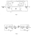
- FIG. 1 is a block diagram depicting a data compression algorithm according to a preferred embodiment of the present invention.
- FIG. 2 is a block diagram depicting a data compression algorithm according to a second preferred embodiment of the present invention.
- FIG. 3 is a flow chart of the compression process of the compression algorithm.
- FIG. 4 is a state diagram showing compression transitions between a COPY mode, a REPEAT mode, and a LITERAL mode.
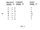
- FIG. 5 is a table depicting a mode transition encoding scheme according to the present invention.
- FIG. 6 is a table depicting a count encoding scheme according to the present invention.
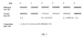
- FIG. 7 is an illustrative example of how the encoder of the present invention compresses a current row of a bit-mapped image into a compressed row given a reference row.
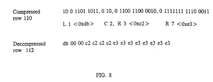
- FIG. 8 is an illustrative example of how the decoder decompresses a compressed row back into the original decompressed row.
- FIG. 1 is a block diagram depicting a data compression algorithm 10 of the present invention, which, in a preferred embodiment, is utilized for printer frame memory compression.
- the data compression algorithm 10 is located within a conventional printer 12, which contains a frame buffer 14 for the temporary storage of an incoming bit-mapped image 16.
- the compression algorithm 10 includes two parts, an encoder 10a for compressing data, and a decoder 10b for decompressing data.
- the purpose of the compression algorithm 10 is to reduce the memory requirement of the frame buffer 14 by using the encoder 10a to compress the bit-mapped image 16 before the bit-mapped image 16 is stored in the frame buffer 14.
- the encoder 10a compresses the bit-mapped image 16, using methods explained below, to create a compressed image 18.
- the compressed image 18 is then transferred from the frame buffer 14 to the decoder 10b where the compressed image 18 is decompressed to recreate the bit-mapped image 16.
- the printer 12 prints the bit-mapped image 16.
- the compression algorithm 10 may be implemented in the hardware of printer 12 or alternatively, implemented in software, which is executed on a standard processing device within the printer (not shown), such as a microprocessor, for instance.
- the compression algorithm 10 of the present invention is simple to implement in hardware because it requires few gates, as explained further below, and is less expensive than the memory saved by the smaller frame buffer 14. Thus, the overall cost of the printer 12 is reduced.
- the compression algorithm 10 is used with a "dumb" printer 30 which lacks sufficient processing power to rasterize data before the data is printed. Therefore, the encoder 10a is located on a host processing device, such a PC 32, for example, and the encoder 10b is located in the dumb printer 30. A bit-mapped image 16 which is to be printed, is compressed by the encoder 10a to produce a compressed image 18. Compressed image 18 is then transferred by the PC 32 to the dumb printer 30 via a parallel interface 38 between the PC 32 and the dumb printer 30. Once the compressed image 18 reaches the dumb printer 30, the decoder 10b decompresses the compressed image 18 back into the bit-mapped image 16 which is then printed by the dumb printer 30.
- the encoder 10a is implemented in software and is executed in within the PC 32.
- the decoder 10b may either be implemented in hardware within the printer 30, or alternatively, implemented in firmware, assuming of course, that the printer 30 contains some form of processor.
- the simplicity of the encoder 10a dispenses with the requirement for an add-on compression board inside the PC 32.
- the lack of an add-on compression board reduces the complexity of the compression system and increases compatibility between the printer 30 and the PC 32.
- the compression algorithm 10 reads a rasterline of an input bit-mapped image 16 and compares the rasterline with the immediately preceding rasterline to check for commonly occurring sequences of bytes.
- the rasterline currently being read by the compression algorithm 10 is referred to as the current row, and the preceding rasterline to which it is compared is referred to as the reference row.
- the current row is compressed by not only identifying a section of bytes in the row that are different from the reference row, as in delta row compression, but also by identifying a section of bytes that are the same as the reference row.
- Each input byte in the current row is then represented in the compressed image 18 by one of the following three modes: 1) COPY, 2) REPEAT, or 3) LITERAL mode.
- the COPY (C) mode indicates that the input byte of the current row is equal to the corresponding byte in the reference row.
- the REPEAT (R) mode indicates that the input byte of the current row is equal to the previous input byte in the current row.
- the LITERAL (L) mode indicates that the input byte is not in the above two modes and must therefore be copied as is to the compressed image 18.
- FIG. 3 a flow chart of the compression modes of the encoder 10a is shown.
- the flow chart of FIG. 3 is explained along with reference to FIGS. 1 and 2.
- the encoder 10a For a given current row in a bit-mapped image 16, the encoder 10a begins compressing the row by reading each byte in the current row, and each corresponding byte in the reference row in sequence (step 40). (If the current row is the first row read from the bit-mapped image 16, then the encoder 10a initializes the reference row to all 0's). The encoder 10a then compares the byte from the current row with the corresponding byte in the reference row (step 41).
- the encoder 10a encodes the byte as being in the COPY mode (step 42). If the byte is not the same as the byte in the reference row, then the encoder 10a reads the next byte in the current row (step 43), and compares it with the previous byte in the current row (step 44). If the current byte is equal the previous byte, then the encoder 10a encodes the byte as being in the REPEAT mode (step 45). If the current byte is not equal the previous byte, then the encoder 10a encodes the byte as being in the LITERAL mode (step 46).
- the mode which is used to encode the current byte, as described above, is the current mode.
- the current mode continues (Step 47) until a different mode is set.
- the COPY Mode (Step 42) continues while each byte in the current row matches the corresponding byte in the reference row.
- the REPEAT mode (Step 45) continues while each byte in the current row matches the preceding byte in the current row.
- the LITERAL MODE (Step 46) continues while each byte in the current row fails to match the corresponding byte in the reference row and the preceding byte in the current row.
- the encoder checks if the byte is the last byte in the current row. If the byte is the last byte in the current row, then the current row becomes the reference row, and the encoder 10a reads the next row, which becomes the new current row. The process above continues until each rasterline in the bit-mapped image 16 is read and compressed.
- the encoder 10a encodes the bytes according to the following mode format: ⁇ COPY mode> ⁇ n> where COPY mode is the current mode, and n is a count of the number of data bytes to be copied from the reference row.
- the encoder 10a For all bytes encoded as being in the REPEAT mode, the encoder 10a encodes the bytes according to the following format: ⁇ REPEAT mode> ⁇ n> ⁇ data bytes> where REPEAT mode is the current mode, n is a count indicating that the following data byte is to be repeated ⁇ n> + 1 times, and the data byte is the byte to be repeated.
- the encoder 10a For all bytes encoded as being in the LITERAL mode, the encoder 10a encodes the bytes according to the following format: ⁇ LITERAL mode> ⁇ n> ⁇ data bytes> where LITERAL is the current mode, n is a count indicating how many data bytes follow, and the data bytes are the bytes of data to be copied.
- the current row once compressed contains sequences of such triplets; a mode code followed by a length code, and optionally followed by one or more data bytes.
- mode sequences C 12 - indicates that 12 bytes are to be copied from reference row when a new row is created from the reference row; R 27 'A' - indicates that the byte 'A' is to be repeated 28 times in the new row; and L 7 'ABCDEFG' - indicates that the seven bytes 'ABCDEFG' are to be written directly to the new row.
- FIG. 4 is a state diagram showing the possible free mode transitions between the COPY mode 50, the REPEAT mode 52, and the LITERAL mode 54.
- the COPY mode 50 may transition either to the REPEAT mode 52, shown by the arrow 60, or to the LITERAL mode 54, shown by the arrow 62.
- the LITERAL mode 54 may transition either to the COPY mode 50, shown by arrow 64, or to the REPEAT mode 52, shown by the arrow 66.
- the REPEAT mode 52 may transition to the COPY mode 50, shown by the arrow 68; the LITERAL mode 54, shown by the arrow 70; and to itself, shown by the loop arrow 72.
- a mode transition from the COPY mode 50 to the COPY mode 50, and a transition from the LITERAL mode 54 to the LITERAL mode 54, will not occur.
- the COPY mode 50 will not follow a previous COPY mode 50 because a COPY sequence of two differing sets of bytes will be combined to form one COPY sequence.
- a LITERAL sequence of two differing sets of bytes will also combined to form one LITERAL sequence.
- the only way to terminate the COPY mode 50 and the LITERAL mode 54 is to change to another mode. This is different from the REPEAT mode 52 in which a REPEAT of one sequence can be followed by another.
- the byte sequence "AAAABB" would berepresented as R 4 'A' followed by R 2'B'.
- Mode transitions between a current mode 82 and a previous mode 80 are shown generally at 78, and correspond to the mode transitions shown in FIG. 4.
- the mode transitions 78 may be divided into categories based on the value of the previous mode in each mode transition. For example, all mode transitions where the previous mode is COPY, is one transition category; all mode transitions where the previous mode is REPEAT, is a second transition category; and all mode transitions where the previous mode is LITERAL, is a third transition category.
- each mode transition in a category is assigned a unique corresponding mode code 84.
- a mode code of '0' is assigned when the current mode is REPEAT
- a mode code of '1' is assigned when the current mode is LITERAL.
- a mode code of '0' is assigned when the current mode is REPEAT
- a mode code of '10' is assigned when the current mode is LITERAL
- a mode code of '11' is assigned when the current mode is COPY.
- a mode code of '0' is assigned when the current mode is COPY
- a mode code of '1' is assigned to when the current mode is REPEAT.
- the mode codes 84 are not explicitly set in the compression algorithm 10, but are rather numerically derived.
- the mode codes 84 are numerically derived by first enumerating the modes COPY, REPEAT, and LITERAL in order. For example, the COPY mode may be made equal to '0', the REPEAT mode may be made equal to '1', and the LITERAL mode may be made equal to '2'. After the modes are enumerated, mode transitions are classified, using what is called a mode bit, by calculating a modulo function between a previous mode 80 and a current mode 82 in a given mode transition 78.
- a modulo function is a arithmetic operation whose result is the remainder of a division operation. For example, the equation "2modulo 3" equals 2, because 2 divided by 3 yields a remainder of 2.
- the mode bit is set to either '0' or '1' according the following:
- the REPEAT mode is set as the initial previous mode, since the REPEAT mode is the only mode that can transition to all three modes.
- the continuity of a mode will not be interrupted by the end of the current row. That is, row boundaries do not affect the compression process except to signal the reading of a new row and to update the reference row.
- each mode code may be followed by a count ⁇ n> of the number of data bytes which follow.
- the counts are also represented in a compressed rasterline as a variable-length code.
- Each count ⁇ n> 90 representing the number of data bytes in a mode, is encoded by a variable-length count code 92.
- the count five represents that the date byte 'A' is to be repeated six times (n + 1), and the count would be replaced with the count code of '11110.
- n/255+1 bytes are used to represent the count 90, among which, the first n/255 bytes are 0xff (hexadecimal 255) and the sum of all bytes is n.
- the encoder 10a arranges the compressed data such that the decoder 10b can fetch the next byte in a compressed rasterline whenever the encoder 10b requires a byte for decoding.
- the variable-length mode codes 84 and the variable-length count codes 92 are grouped into bytes while data bytes follow in natural order.
- the variable-length mode codes 84 include the bits (0, 1, 10, 11)
- the variable-length count codes 92 include the set (0, 10, 1100, 1101, 1110, 11110, 111110, 111111).
- the data bytes include the following: 1) the bytes following a REPEAT mode code, 2) the bytes following a LITERAL mode code, and 3) the count bytes following the count code 1110 (when the count is greater than 7 and less than 255).
- FIG. 7 is an example of how the encoder 10a of the present invention compresses a current row 102 of a bit-mapped image into a compressed row 104 given a reference row 100.
- the reference row 102 contains all zeros and only six bytes (0, 1, 2 ,3,4, 5,) in the current row 100 and reference row 102 are shown.
- the commas shown in the compressed row 104 are for reference only, and delimit separate mode sequences.
- the current mode is COPY.
- the default previous mode is REPEAT mode
- the first set of bits '11' in the compressed row 104 is a mode code indicating a mode transition from REPEAT to COPY.
- the following set of bits '10' is a count code, indicating that two bytes are to by copied from the reference row 100.
- the second mode code '0' in the compressed row 104 indicates a mode transition from COPY to REPEAT (see FIG. 5).
- the next set of bits '0' is a count code indicating that the following data byte '1111111', is to be repeated twice (n + 1).
- Byte four in the current row 102 is not the same as byte four in the reference row 100, and does not repeat, so the byte four must be copied directly to the compressed row 104.
- the mode code '10' represents the mode transition from REPEAT to LITERAL (see FIG. 5), and the next bit '0' is a count code indicating the following byte '10101101' is to be copied directly when the compressed row 104 is decompressed.
- Byte five in the compressed row 102 is identical to the corresponding byte in the reference row 100 and may be copied from the reference row 100.
- the bit '0' is a mode code indicating a transition from LITERAL to COPY mode (see FIG. 5), and the next bit '0' is count code indicating that one byte from the reference row 100 is to be copied twice (n + 1).
- the present invention provides compression ratios which are better than delta row compression.
- the set of variable-length mode codes and count codes described above in a preferred embodiment of the present invention are not optimal for all images. However, they have been found to be quite effective for images that are likely to be printed on a printer including text and graphics. Other sets of codes may be used for different images. Furthermore, an image can be divided into bands such that each band uses one set of codes. A code index at the beginning of the decompressed row for a band can then be used to indicate the variable-length codes.
- the worst compression case for the compression algorithm 10 is when all bytes in the current row are in the LITERAL mode. In this case n bytes are expanded to n + 0.5 + (n / 255) + 1 bytes, representing a size increase over the reference row by approximately about 0.4 percent.
- FIG. 8 an example of how the decoder 10b (FIG. 1) decompresses a compressed row 110 into a decompressed row 112.
- the data bytes in this example are shown in hexadecimal and, although not shown, the reference row is all zeros, as in the previous example. Also, as in FIG. 7, each mode sequence in the compressed row 110 is separated by a comma for reference.
- the first mode sequence contains a '10' mode code and a count code of '0' (1 byte). Since previous mode is initially set to REPEAT, the mode code '10' indicates a mode transition from REPEAT to LITERAL mode (see FIG. 5). This inode sequence instructs the decoder to copy the single data byte '1101 1011', which is db in hexadecimal, directly to the decompressed row 112.
- the second mode sequence contains a '0' mode code and a count code of '10' (2 bytes). Since the previous mode was LITERAL, the mode code '0' indicates a mode transition from LITERAL to COPY (see FIG. 5). This mode sequence instructs the decoder to copy two bytes from the reference row, which are all zero, to the decompressed row 112.
- the third mode sequence contains a '0' mode code and a count code of '1100' (3 bytes). Since the previous mode was COPY, the mode code '0' indicates a mode transition from COPY to REPEAT mode (see FIG. 5). This mode sequence instructs the decoder to copy the data byte '11000010', which is c3 in hexadecimal, to the decompressed row 112 four times.
- the fourth mode sequence contains a '0' mode code and a count code of '1111111' (7 bytes). Since the previous mode was REPEAT, the mode code '0' indicates a mode transition from REPEAT to REPEAT mode (see FIG. 5). This mode sequence instructs the decoder to copy the data byte '11100011', which is e3 in hexadecimal, to the decompressed row eight times.
- the decoder 10b which decodes mode codes and count codes, can be implemented easily in hardware with very few gates (because there are not many states).
- the decompression speed is mainly bounded by the memory access time. Therefore, the compression algorithm 10 of the present invention should render slightly faster decompression rates than Delta Row compression. This is due in part because the compression algorithm 10 has a higher compression ratio and thus fewer memory accesses.
- the compression algorithm 10 also includes a fast compression rate. On a Pentium processor manufactured by Intel Corporation, for example, the compression algorithm 10 is capable of compressing three Megabytes of data per second.
Landscapes
- Engineering & Computer Science (AREA)
- Multimedia (AREA)
- Physics & Mathematics (AREA)
- General Physics & Mathematics (AREA)
- Theoretical Computer Science (AREA)
- Compression, Expansion, Code Conversion, And Decoders (AREA)
- Compression Of Band Width Or Redundancy In Fax (AREA)
Applications Claiming Priority (2)
| Application Number | Priority Date | Filing Date | Title |
|---|---|---|---|
| US309018 | 1994-09-20 | ||
| US08/309,018 US5617517A (en) | 1994-09-20 | 1994-09-20 | Two-dimensional method and system for compressing bi-level images |
Publications (3)
| Publication Number | Publication Date |
|---|---|
| EP0703549A2 true EP0703549A2 (fr) | 1996-03-27 |
| EP0703549A3 EP0703549A3 (fr) | 1996-10-02 |
| EP0703549B1 EP0703549B1 (fr) | 2002-05-22 |
Family
ID=23196318
Family Applications (1)
| Application Number | Title | Priority Date | Filing Date |
|---|---|---|---|
| EP95306611A Expired - Lifetime EP0703549B1 (fr) | 1994-09-20 | 1995-09-20 | Méthode et système à deux dimensions pour la compression d'images à deux niveaux |
Country Status (4)
| Country | Link |
|---|---|
| US (1) | US5617517A (fr) |
| EP (1) | EP0703549B1 (fr) |
| JP (1) | JP3211640B2 (fr) |
| DE (1) | DE69526764T2 (fr) |
Cited By (7)
| Publication number | Priority date | Publication date | Assignee | Title |
|---|---|---|---|---|
| EP1001612A1 (fr) * | 1998-11-16 | 2000-05-17 | Hewlett-Packard Company | Compression de données d'images dans un procédé de traitement de documents composites |
| EP1095459A4 (fr) * | 1998-07-02 | 2003-01-29 | Intel Corp | Algorithmes et architectures en temps reel destines au codage d'images comprimees par des techniques de transformation en ondelettes discretes |
| GB2386783A (en) * | 2002-02-27 | 2003-09-24 | Hewlett Packard Co | Lossless page data compression interleaving colour plane data |
| EP1351190A3 (fr) * | 2002-03-28 | 2005-11-16 | Hewlett-Packard Company | Compression de données d'images à niveaux de gris et binaires |
| US6972868B1 (en) | 2000-11-09 | 2005-12-06 | Hewlett-Packard Development Company, L.P. | Image data compression method |
| WO2012032311A1 (fr) * | 2010-09-10 | 2012-03-15 | Imagination Technologies Limited | Compression sans perte de données paramétrées à accès aléatoire pour systèmes graphiques informatiques 3d |
| EP2087471A4 (fr) * | 2006-08-22 | 2018-08-22 | Monotype Imaging Inc. | Procédé pour réduire la taille et augmenter la vitesse pour une génération de polices d'instructions |
Families Citing this family (8)
| Publication number | Priority date | Publication date | Assignee | Title |
|---|---|---|---|---|
| US5724450A (en) * | 1994-09-30 | 1998-03-03 | Apple Computer, Inc. | Method and system for color image compression in conjunction with color transformation techniques |
| JP3604795B2 (ja) * | 1995-11-30 | 2004-12-22 | キヤノン株式会社 | 印字制御装置と印字制御方法 |
| JP3631848B2 (ja) * | 1996-06-28 | 2005-03-23 | 富士通株式会社 | 画像表示システム |
| US5877711A (en) * | 1997-09-19 | 1999-03-02 | International Business Machines Corporation | Method and apparatus for performing adaptive data compression |
| US7437483B1 (en) * | 1999-03-24 | 2008-10-14 | Microsoft Corporation | System and method for transferring a compressed data file to a peripheral device |
| JP2001053620A (ja) * | 1999-08-13 | 2001-02-23 | Canon Inc | 符号化方法及び符号化装置、復号化方法及び復号化装置、記憶媒体 |
| JP2004221633A (ja) * | 2003-01-09 | 2004-08-05 | Ricoh Co Ltd | 画像処理装置、画像処理用プログラム及び記憶媒体 |
| CN117221414B (zh) * | 2023-11-09 | 2024-01-16 | 东莞中杰艾克森电子有限公司 | 一种调制解调器数据智能传输方法 |
Family Cites Families (21)
| Publication number | Priority date | Publication date | Assignee | Title |
|---|---|---|---|---|
| US3717851A (en) * | 1971-03-03 | 1973-02-20 | Ibm | Processing of compacted data |
| US4499548A (en) * | 1980-07-02 | 1985-02-12 | Hewlett-Packard Company | Data compression apparatus |
| US4464650A (en) * | 1981-08-10 | 1984-08-07 | Sperry Corporation | Apparatus and method for compressing data signals and restoring the compressed data signals |
| US4558302A (en) * | 1983-06-20 | 1985-12-10 | Sperry Corporation | High speed data compression and decompression apparatus and method |
| US4694352A (en) * | 1984-09-21 | 1987-09-15 | Canon Kabushiki Kaisha | Image information processing system |
| GB2172127B (en) * | 1985-03-06 | 1988-10-12 | Ferranti Plc | Data compression system |
| US5047955A (en) * | 1987-06-19 | 1991-09-10 | Eastman Kodak Company | Electronic collation |
| JP3061278B2 (ja) * | 1988-04-29 | 2000-07-10 | ゼロックスコーポレーション | 可変ビット長コード語のビット長通信方法 |
| US4996690A (en) * | 1988-08-26 | 1991-02-26 | Stac Electronics | Write operation with gating capability |
| US5046027A (en) * | 1988-11-08 | 1991-09-03 | Massachusetts General Hospital | Apparatus and method for processing and displaying images in a digital procesor based system |
| US4930142A (en) * | 1988-12-06 | 1990-05-29 | Stac, Inc. | Digital phase lock loop |
| US5126739A (en) * | 1989-01-13 | 1992-06-30 | Stac Electronics | Data compression apparatus and method |
| US5003307A (en) * | 1989-01-13 | 1991-03-26 | Stac, Inc. | Data compression apparatus with shift register search means |
| US5016009A (en) * | 1989-01-13 | 1991-05-14 | Stac, Inc. | Data compression apparatus and method |
| US5146221A (en) * | 1989-01-13 | 1992-09-08 | Stac, Inc. | Data compression apparatus and method |
| US5060286A (en) * | 1989-01-19 | 1991-10-22 | Hewlett-Packard Company | Raster row and byte group graphics images data compression method |
| JP3083344B2 (ja) * | 1990-05-25 | 2000-09-04 | ヒューレット・パッカード・カンパニー | データの圧縮及び圧縮解除方法 |
| GB2267624B (en) * | 1992-05-05 | 1995-09-20 | Acorn Computers Ltd | Image data compression |
| US5274472A (en) * | 1992-05-21 | 1993-12-28 | Xerox Corporation | High addressability image generator using pseudo interpolation of video and screen data |
| US5471563A (en) * | 1992-07-10 | 1995-11-28 | Microsoft Corporation | System and method for automatic resolution reduction |
| US5467435A (en) * | 1992-07-10 | 1995-11-14 | Microsoft Corporation | System and method for mode switching |
-
1994
- 1994-09-20 US US08/309,018 patent/US5617517A/en not_active Expired - Lifetime
-
1995
- 1995-09-19 JP JP24037495A patent/JP3211640B2/ja not_active Expired - Lifetime
- 1995-09-20 EP EP95306611A patent/EP0703549B1/fr not_active Expired - Lifetime
- 1995-09-20 DE DE69526764T patent/DE69526764T2/de not_active Expired - Fee Related
Non-Patent Citations (1)
| Title |
|---|
| None |
Cited By (20)
| Publication number | Priority date | Publication date | Assignee | Title |
|---|---|---|---|---|
| EP1095459A4 (fr) * | 1998-07-02 | 2003-01-29 | Intel Corp | Algorithmes et architectures en temps reel destines au codage d'images comprimees par des techniques de transformation en ondelettes discretes |
| US6373583B1 (en) | 1998-11-16 | 2002-04-16 | Hewlett-Packard Company | Compound document page data compression |
| EP1001612A1 (fr) * | 1998-11-16 | 2000-05-17 | Hewlett-Packard Company | Compression de données d'images dans un procédé de traitement de documents composites |
| US6977738B2 (en) | 1998-11-16 | 2005-12-20 | Hewlett-Packard Development Company, L.P. | Compound document page data compression |
| US6972868B1 (en) | 2000-11-09 | 2005-12-06 | Hewlett-Packard Development Company, L.P. | Image data compression method |
| US7532358B2 (en) | 2002-02-27 | 2009-05-12 | Hewlett-Packard Development Company, L.P. | Hardware implemented loss-less page data compressor/decompressor |
| GB2386783A (en) * | 2002-02-27 | 2003-09-24 | Hewlett Packard Co | Lossless page data compression interleaving colour plane data |
| GB2386783B (en) * | 2002-02-27 | 2005-09-21 | Hewlett Packard Co | Hardware implemented loss-less page data compressor/decompressor |
| DE10308531B4 (de) * | 2002-02-27 | 2007-03-29 | Hewlett-Packard Development Co., L.P., Houston | Hardwareimplementierte verlustfreie Seitendatenkomprimierungseinrichtung/-dekomprimierungseinrichtung |
| EP1351190A3 (fr) * | 2002-03-28 | 2005-11-16 | Hewlett-Packard Company | Compression de données d'images à niveaux de gris et binaires |
| US7373008B2 (en) | 2002-03-28 | 2008-05-13 | Hewlett-Packard Development Company, L.P. | Grayscale and binary image data compression |
| EP2087471A4 (fr) * | 2006-08-22 | 2018-08-22 | Monotype Imaging Inc. | Procédé pour réduire la taille et augmenter la vitesse pour une génération de polices d'instructions |
| WO2012032311A1 (fr) * | 2010-09-10 | 2012-03-15 | Imagination Technologies Limited | Compression sans perte de données paramétrées à accès aléatoire pour systèmes graphiques informatiques 3d |
| US8836696B2 (en) | 2010-09-10 | 2014-09-16 | Imagination Technologies, Limited | Random accessible lossless parameter data compression for tile based 3D computer graphics systems |
| US9292960B2 (en) | 2010-09-10 | 2016-03-22 | Imagination Technologies Limited | Random accessible lossless parameter data compression for tile based 3D computer graphics systems |
| EP3035288A1 (fr) * | 2010-09-10 | 2016-06-22 | Imagination Technologies Limited | Compression de données de paramètre sans perte à accès aléatoire pour des systèmes graphiques informatiques 3d basés sur une mosaïque |
| US10380781B2 (en) | 2010-09-10 | 2019-08-13 | Imagination Technologies Limited | Random accessible lossless parameter data compression for tile based 3D computer graphics systems |
| US11043016B2 (en) | 2010-09-10 | 2021-06-22 | Imagination Technologies Limited | Random accessible lossless parameter data compression for tile based 3D computer graphics systems |
| US11625883B2 (en) | 2010-09-10 | 2023-04-11 | Imagination Technologies Limited | Random accessible lossless parameter data compression for tile based 3D computer graphics systems |
| US12333641B2 (en) | 2010-09-10 | 2025-06-17 | Imagination Technologies Limited | Random accessible lossless parameter data compression for tile based 3D computer graphics systems |
Also Published As
| Publication number | Publication date |
|---|---|
| DE69526764T2 (de) | 2002-09-05 |
| JPH08289157A (ja) | 1996-11-01 |
| JP3211640B2 (ja) | 2001-09-25 |
| US5617517A (en) | 1997-04-01 |
| DE69526764D1 (de) | 2002-06-27 |
| EP0703549B1 (fr) | 2002-05-22 |
| EP0703549A3 (fr) | 1996-10-02 |
Similar Documents
| Publication | Publication Date | Title |
|---|---|---|
| US4546385A (en) | Data compression method for graphics images | |
| EP1285399B1 (fr) | Compression amelioree d'images a niveaux de gris | |
| EP0703549B1 (fr) | Méthode et système à deux dimensions pour la compression d'images à deux niveaux | |
| US5999710A (en) | Merge plane generation for a data processing pipeline | |
| CA2345218C (fr) | Methode de compression de documents numeriques avec controle de la qualite de l'image et du taux de compression | |
| US6320981B1 (en) | Image processing system and image processing method | |
| US5659631A (en) | Data compression for indexed color image data | |
| EP0886205B1 (fr) | Pipeline pour traitement de données de type multivoies | |
| US5940585A (en) | Data merge unit | |
| JPH08235346A (ja) | 画像処理装置 | |
| US7167259B2 (en) | System and method for merging line work objects using tokenization and selective compression | |
| JP3461309B2 (ja) | ハフマン符号化データ圧縮装置 | |
| US5694125A (en) | Sliding window with big gap data compression system | |
| US20010043747A1 (en) | Signal processing equipment | |
| EP0683599A1 (fr) | Appareil et procédé de traitement d'images | |
| JPH06320802A (ja) | 画像処理装置 | |
| US5636294A (en) | Method and apparatus for truncation of images during data compression | |
| US4972497A (en) | Image coding system | |
| US5901251A (en) | Arithmetic coding compressor using a context model that is adaptive to variable length patterns in bi-level image data | |
| EP0768002B1 (fr) | Algorithme a pertes pour compression et expansion de donnees de representation d'image | |
| US5880688A (en) | Arithmetic coding context model that adapts to the amount of data | |
| EP0820186B1 (fr) | Processeur de signaux | |
| US6272256B1 (en) | Fast compression of periodic halftoned bitonal images | |
| GB2305277A (en) | A lossy data compression method | |
| JP2005260420A (ja) | データ圧縮装置およびデータ圧縮プログラム |
Legal Events
| Date | Code | Title | Description |
|---|---|---|---|
| PUAI | Public reference made under article 153(3) epc to a published international application that has entered the european phase |
Free format text: ORIGINAL CODE: 0009012 |
|
| AK | Designated contracting states |
Kind code of ref document: A2 Designated state(s): DE FR GB |
|
| PUAL | Search report despatched |
Free format text: ORIGINAL CODE: 0009013 |
|
| AK | Designated contracting states |
Kind code of ref document: A3 Designated state(s): DE FR GB |
|
| 17P | Request for examination filed |
Effective date: 19970303 |
|
| 17Q | First examination report despatched |
Effective date: 20000314 |
|
| GRAG | Despatch of communication of intention to grant |
Free format text: ORIGINAL CODE: EPIDOS AGRA |
|
| GRAG | Despatch of communication of intention to grant |
Free format text: ORIGINAL CODE: EPIDOS AGRA |
|
| GRAH | Despatch of communication of intention to grant a patent |
Free format text: ORIGINAL CODE: EPIDOS IGRA |
|
| GRAH | Despatch of communication of intention to grant a patent |
Free format text: ORIGINAL CODE: EPIDOS IGRA |
|
| GRAA | (expected) grant |
Free format text: ORIGINAL CODE: 0009210 |
|
| REG | Reference to a national code |
Ref country code: GB Ref legal event code: FG4D |
|
| REF | Corresponds to: |
Ref document number: 69526764 Country of ref document: DE Date of ref document: 20020627 |
|
| ET | Fr: translation filed | ||
| PLBE | No opposition filed within time limit |
Free format text: ORIGINAL CODE: 0009261 |
|
| STAA | Information on the status of an ep patent application or granted ep patent |
Free format text: STATUS: NO OPPOSITION FILED WITHIN TIME LIMIT |
|
| 26N | No opposition filed |
Effective date: 20030225 |
|
| PGFP | Annual fee paid to national office [announced via postgrant information from national office to epo] |
Ref country code: DE Payment date: 20070913 Year of fee payment: 13 |
|
| PGFP | Annual fee paid to national office [announced via postgrant information from national office to epo] |
Ref country code: GB Payment date: 20070919 Year of fee payment: 13 |
|
| PGFP | Annual fee paid to national office [announced via postgrant information from national office to epo] |
Ref country code: FR Payment date: 20070914 Year of fee payment: 13 |
|
| GBPC | Gb: european patent ceased through non-payment of renewal fee |
Effective date: 20080920 |
|
| REG | Reference to a national code |
Ref country code: FR Ref legal event code: ST Effective date: 20090529 |
|
| PG25 | Lapsed in a contracting state [announced via postgrant information from national office to epo] |
Ref country code: DE Free format text: LAPSE BECAUSE OF NON-PAYMENT OF DUE FEES Effective date: 20090401 |
|
| PG25 | Lapsed in a contracting state [announced via postgrant information from national office to epo] |
Ref country code: FR Free format text: LAPSE BECAUSE OF NON-PAYMENT OF DUE FEES Effective date: 20080930 |
|
| PG25 | Lapsed in a contracting state [announced via postgrant information from national office to epo] |
Ref country code: GB Free format text: LAPSE BECAUSE OF NON-PAYMENT OF DUE FEES Effective date: 20080920 |