EP0703645B1 - Ensemble de connexion ayant un élément codé de verrouillage secondaire - Google Patents
Ensemble de connexion ayant un élément codé de verrouillage secondaire Download PDFInfo
- Publication number
- EP0703645B1 EP0703645B1 EP19950113184 EP95113184A EP0703645B1 EP 0703645 B1 EP0703645 B1 EP 0703645B1 EP 19950113184 EP19950113184 EP 19950113184 EP 95113184 A EP95113184 A EP 95113184A EP 0703645 B1 EP0703645 B1 EP 0703645B1
- Authority
- EP
- European Patent Office
- Prior art keywords
- housing
- coding
- connector assembly
- secondary locking
- complementary
- Prior art date
- Legal status (The legal status is an assumption and is not a legal conclusion. Google has not performed a legal analysis and makes no representation as to the accuracy of the status listed.)
- Expired - Lifetime
Links
- 230000007246 mechanism Effects 0.000 title claims description 18
- 230000000295 complement effect Effects 0.000 claims description 35
- 230000013011 mating Effects 0.000 claims description 30
- 230000000712 assembly Effects 0.000 claims description 11
- 238000000429 assembly Methods 0.000 claims description 11
- 230000008878 coupling Effects 0.000 claims description 9
- 238000010168 coupling process Methods 0.000 claims description 9
- 238000005859 coupling reaction Methods 0.000 claims description 9
- 238000003780 insertion Methods 0.000 claims description 4
- 230000037431 insertion Effects 0.000 claims description 4
- 238000007789 sealing Methods 0.000 description 6
- 230000014759 maintenance of location Effects 0.000 description 3
- 239000003086 colorant Substances 0.000 description 2
- 238000001514 detection method Methods 0.000 description 2
- 230000000007 visual effect Effects 0.000 description 2
- 230000000881 depressing effect Effects 0.000 description 1
- 238000002347 injection Methods 0.000 description 1
- 239000007924 injection Substances 0.000 description 1
- 238000012986 modification Methods 0.000 description 1
- 230000004048 modification Effects 0.000 description 1
- 238000000465 moulding Methods 0.000 description 1
- 239000004033 plastic Substances 0.000 description 1
- 229920003023 plastic Polymers 0.000 description 1
Images




Classifications
-
- H—ELECTRICITY
- H01—ELECTRIC ELEMENTS
- H01R—ELECTRICALLY-CONDUCTIVE CONNECTIONS; STRUCTURAL ASSOCIATIONS OF A PLURALITY OF MUTUALLY-INSULATED ELECTRICAL CONNECTING ELEMENTS; COUPLING DEVICES; CURRENT COLLECTORS
- H01R13/00—Details of coupling devices of the kinds covered by groups H01R12/70 or H01R24/00 - H01R33/00
- H01R13/64—Means for preventing incorrect coupling
- H01R13/645—Means for preventing incorrect coupling by exchangeable elements on case or base
- H01R13/6453—Means for preventing incorrect coupling by exchangeable elements on case or base comprising pin-shaped elements, capable of being orientated in different angular positions around their own longitudinal axes, e.g. pins with hexagonal base
-
- H—ELECTRICITY
- H01—ELECTRIC ELEMENTS
- H01R—ELECTRICALLY-CONDUCTIVE CONNECTIONS; STRUCTURAL ASSOCIATIONS OF A PLURALITY OF MUTUALLY-INSULATED ELECTRICAL CONNECTING ELEMENTS; COUPLING DEVICES; CURRENT COLLECTORS
- H01R13/00—Details of coupling devices of the kinds covered by groups H01R12/70 or H01R24/00 - H01R33/00
- H01R13/40—Securing contact members in or to a base or case; Insulating of contact members
- H01R13/42—Securing in a demountable manner
- H01R13/436—Securing a plurality of contact members by one locking piece or operation
- H01R13/4367—Insertion of locking piece from the rear
- H01R13/4368—Insertion of locking piece from the rear comprising a temporary and a final locking position
Definitions
- This invention relates to a connector assembly having a secondary locking mechanism and a coding mechanism for ensuring coupling to the correct complementary assembly, wherein the coding member is incorporated on the secondary locking mechanism.
- electrical connector assemblies comprising a first insulative housing for receiving electrical terminals therein, and further member comprising a movable secondary locking mechanism that can be activated from a pre-assembly to a fully assembled position to securely lock the terminals within the housing once they have been fully inserted thereinto.
- coding means between mating connectors to ensure that the correct connectors are coupled together. It is however a continuous requirement to increase the cost-effectiveness, reliability and robustness of electrical connectors. It is also desirable to provide a large number of coding possibilities for certain applications.
- many connectors must enable reliable sealing due to the harsh environments in which some are placed, for example in automotive applications.
- a connector assembly as defined in claim 1.
- a connector assembly comprising an insulative housing and a secondary locking mechanism mountable thereto in a pre-assembly position for receiving terminals in the housing, and movable to a fully assembled position such that the terminals are securely locked within the housing, the connector assembly further comprising coding means interengageable with coding means of a complementary connector assembly matable therewith, wherein the coding means is an integral extension of the secondary locking mechanism.
- the extension may have a prismatic, coded shape insertable into a code member receiving cavity of the housing such that the complementary code means of the complementary code assembly is insertable into the remaining space in the code member receiving cavity adjacent the code member.
- the secondary locking mechanism can be mounted from a terminal receiving face whereby the coding means is substantially centrally positioned such that a sealing surface around the mating face of the connector is unbroken. The latter thus enables easy and effective sealing of this connector whilst nevertheless providing secondary locking.
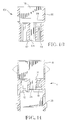
- a connector assembly for receiving tab terminals therein comprises an insulative housing 4 and a secondary locking member 6.
- the housing 4 comprises a terminal mounting section 8 having tab terminal receiving cavities 10 extending axially therethrough from a mating face 12 to a terminal receiving face 14.
- a shroud 16 extends axially away from the terminal receiving face 14 and forms a cavity 18 therein for receiving the secondary locking member.
- a further shroud 20 extends axially from the mating face 12 and forms a cavity 22 therein for receiving a complementary connector assembly that will be described further on.
- the terminal receiving section 8 comprises a centrally positioned coding cavity 24 that extends axially between the terminal receiving and mating faces 14,12 respectively.
- the secondary locking mechanism 6 comprises a body section 26 extending axially between a terminal entry in 28 and a terminal locking face 30, and a coding bar 32 that extends axially from the locking face 30 to a mating end 34.
- the coding bar 32 is prismatic and may be comprised of more than one prismatic bar member, for example two as shown in Figures 18e-18h whereby the two coding bar members are denoted 32' and 32''.
- the secondary locking member 6 is mountable to the housing 4 by insertion of the coding bar 32 into the housing coding cavity 24 and simultaneous insertion of the body section 26 into the cavity 18.
- the windows 40 have a sufficient width W transverse to the axial direction, to allow transverse sliding of the protrusions 36 for the reasons described herebelow.
- the secondary locking mechanism has a protrusion 46 that engages in a cutout 48 of the shroud 16 for providing further axial retention of the secondary locking member with respect to the housing, when in the fully assembled position.
- a nob 52 for depressing the secondary locking mechanism in the direction D from the preassembled to the fully assembled position.
- the secondary locking member and the housing have complementary recesses and protrusions 52,54,56,58 at their abutting faces 14 and 30 that inter-engage to ensure that the secondary locking member 6 is inserted correctly into the cavity 18. If it is not correctly inserted, for example at 180° rotation about the axial axis, then the raised portions 56 and 54 of the secondary locking member and housings 6,4 respectively will abut and prevent engagement of the latches 36 in the cutouts 40, thus ensuring that preassembly theretogether is not possible.
- the coding bar 32 occupies some of the space within the coding cavity 24 of the housing 4, whereby the mating end 34 projects beyond the mating face 12 of the terminal receiving section 8.
- a complementary connector assembly for mating to the connector assembly of Figures 1-6 comprising a housing 104 and a secondary locking mechanism 106.
- the complementary connector assembly has many similar features and functions as the connector assembly of Figure 1-6 and these features will be denoted with the same number raised to 100. Similar features can be understood by making reference to the description of Figures 1-6.
- the housing 104 has a terminal receiving section 108 having cavities 110 extending therethrough between a terminal receiving face 114 and a mating face 112, the cavities 110 for receiving receptacle terminals for mating with tab terminals of the connector assembly 4,6.
- the outer periphery 60 of the terminal receiving section 108 is substantially the same prismatic shape as the cavity 20 of the shroud 22 and is receivable therein mating the connector assemblies 4,104.
- the housing 104 similarly has a shroud 116 extending axially from the terminal receiving face 114, forming a cavity 118 for receiving the secondary locking member 106 therein.
- the shroud 116 also has windows 140 for engagement with latch protrusions 136 of the secondary connector member, which is also slidable in the direction of arrow D from a preassembly to a fully assembled position.
- the secondary locking member 106 also comprises one or more coding bars 132 that extends axially in a prismatic shape from the locking end face 130 to a mating end 134.
- the mating end 134 of the coding bar 132 is however substantially flush with the mating face 112 of the housing 104 when assembled thereto.
- the housing 104 also comprises an axially extending centrally positioned coding cavity 124 that is substantially aligned with the coding cavity 24 of the complementary connector housing 4 when the connector assemblies are coupled together.
- the coding bar 132 thus occupies some of the space of the coding cavity 124 when assembled thereto in a manner complementary to the coding bar 32 within the coding cavity 24, such that when the complementary assembly 104,106 is inserted into the shroud cavity 22 of the connector assembly 4,6, then the coding bar 32 is inserted into the coding cavity 124 of the complementary connector assembly 124.
- Full mating of the connector assemblies is complete when the mating faces 12,112 abut.
- the coding bar 32 of the connector assembly 4,6 thus projects beyond the housing mating face 12 and into the coding cavity 124 of the complementary connector housing 104 alongside and interleaving with the coding bar 132 which is also disposed within the coding cavity 124 of the complementary connector housing.
- the complementary prismatic profiles of the coding bars 32, 132 are made in such a way that if either of the secondary locking members 106 or 6 have not been moved into their fully assembled positions, the mating ends 134,34 of the coding bars abut each other and prevent coupling of the connector assemblies.
- the coding bars thus also have the function of preventing coupling of the connector assemblies if the secondary locking members are not properly engaged.
- Figures 18a-18h show various coding bar shapes of the male terminal connector assembly 4,6 that are complementary to the coding bar profiles of Figures 16a-16h respectively.
- the connector housing 4 assembled with the secondary locking member 6 of Figures 18a will thus be matable (when fully assembled) to the complementary connector housing 104 assembled to the secondary locking member 106 of Figure 16a, however they would not be matable with the complementary housing was assembled to any of the other secondary locking members of Figures 16b-16h. Only the combinations of secondary locking members 6,106 from Figures 18 and 16 having the same letter (e.g. 18c is complementary to 16c) enables those connector assemblies to be mated together.
- the housing 4 may comprise axially extending coding recesses 70,72 on the shroud 20, complementary and cooperable with coding protrusions 74,76 extending longitudinally along the outer periphery 60 of the terminal receiving section 108 of the complementary housing 104. Coding combinations are thus created by varying the position and number of the complementary recesses and protrusions (70,72,74,76). The number of the latter coding possibilities thus multiplies with the number of coding combinations of the complementary coding bars 32,132, thus providing a great number of coding combinations.
- the housings 4,104 with matching coding can also be provided with various matching colours corresponding to the various matching coding combinations for easy distinction.
- the coding bar of the male connector assembly 104,106 is well protected as it does not project beyond the mating face 112.
- the connector assembly for receiving tab terminals 4,6 has a shroud 20 that protects not only the tabs terminals from damage, but also the coding bar 32 that projects beyond the mating face 12. Due to the positioning of the coding bars on the secondary locking members and integral therewith, they cannot be lost. They also provide the double function of ensuring correct coupling of connector assemblies, and preventing coupling if the secondary locking members are not fully assembled to the housings.
- the secondary locking members can be injection moulded from plastics of different colours for each coding combination, whereby for example the complementary secondary locking members of Figures 18a and 16a would have the same colour, thereby assisting the visual detection of connector assemblies for coupling together.
- the coding bars are on the secondary locking housings, they cannot get lost, and furthermore due to their prismatic shape extending from the main body of the secondary locking member they can be easily injected with small modifications to the moulding dies without a redesign of the whole die.
- the number of coding combinations is greatly increased by providing further coding members on the housings (4,104). The latter can also be colour matched for easy visual detection.
- the coding bar 32 is positioned within the area surrounded by the shroud 20, and is assembled to the connector housing from a terminal receiving end.
- the latter allows the shroud 20 to remain unbroken around the periphery such that the inner surface of the shroud can be used as an effective sealing surface for sealing between the coupled connectors.
- the cutout 48 could be removed, and the latch cutouts 40 replaced with protrusions, and a seal positioned over the terminal receiving face of the secondary locking member 6 for effective sealing of the connector, if this was required.
- the coding members accomplish the function of ensuring full assembly of the secondary locking members and prevent coupling of connector assemblies if this is not the case.
Landscapes
- Connector Housings Or Holding Contact Members (AREA)
- Details Of Connecting Devices For Male And Female Coupling (AREA)
Claims (9)
- Assemblage de connecteur comprenant un boítier isolant (4, 104) et un élément de verrouillage secondaire (6, 106), pouvant être monté fermement sur celui-ci dans une première position de pré-assemblage, en vue de l'insertion des bornes dans les cavités (10, 110) du boítier (4, 104), les cavités (10, 110) s'étendant axialement entre une face d'accouplement (12, 112) et une face de réception des bornes (14, 114) d'une section de bornes (8, 108) du boítier (4, 104), l'élément de verrouillage secondaire (6, 106) pouvant être déplacé vers une deuxième position d'assemblage complet, pour verrouiller les bornes dans les cavités du boítier (10, 110), caractérisé en ce que l'élément de verrouillage secondaire (6, 106) comprend une barre de codage (32, 132), s'étendant axialement d'une face d'extrémité de verrouillage correspondante (30, 130) vers une extrémité d'accouplement (34, 134), la barre de codage pouvant être insérée dans une cavité de réception de la barre de codage (24, 124) du boítier, s'étendant axialement à travers la section des bornes (8, 108), la barre de codage pouvant être imbriquée dans une barre de codage complémentaire d'un assemblage de connecteur complémentaire pour permettre l'accouplement d'assemblages de connecteur à codage spécifique concordant, uniquement lorsque le mécanisme de verrouillage secondaire (6, 106) est complètement assemblé au boítier (4, 104).
- Assemblage de connecteur selon la revendication 1, caractérisé en ce que la barre de codage (32, 132) est prismatique.
- Assemblage de connecteur selon l'une quelconque des revendications précédentes, caractérisé en ce que le boítier (4, 104) comprend une enveloppe (16, 116), s'étendant axialement à l'écart de la face de réception des bornes (14, 114), pour former une cavité (18, 118) en vue de la réception de l'élément de verrouillage secondaire (6, 106) lors de l'assemblage correspondant.
- Assemblage de connecteur selon l'une quelconque des revendications précédentes, caractérisé en ce que la face d'extrémité de verrouillage (30, 130) de l'élément de verrouillage secondaire (6, 106) peut être montée contre la face de réception des bornes (14, 114) du boítier (4, 104), les faces (30, 130; 14, 114) comportant des saillies et des évidements à engagement réciproque complémentaire (54, 58; 52, 56), pour empêcher l'assemblage de l'élément de verrouillage secondaire (6, 106) sur le boítier (4, 104), sauf en cas d'orientation correcte par rapport à celui-ci.
- Assemblage de connecteur selon l'une quelconque des revendications précédentes, caractérisé en ce que la cavité de codage (24, 124) et agencée en un emplacement central dans la section des bornes (8, 108).
- Assemblage de connecteur selon l'une quelconque des revendications précédentes, caractérisé en ce que l'extrémité d'accouplement (34) de la barre de codage (32) déborde au-delà de la face d'accouplement (12) de la section des bornes (8).
- Assemblage de connecteur selon la revendication 6, caractérisé en ce que le boítier (4) comporte une enveloppe (20), s'étendant axialement à partir de la face d'accouplement (12) et formant une cavité (22), pour recevoir une section de bornes (108) d'un connecteur complémentaire.
- Assemblage de connecteur selon l'une quelconque des revendications 1 à 5, caractérisé en ce que l'extrémité d'accouplement (134) de la barre de codage (132) ne déborde pratiquement pas au-delà de la face d'accouplement (112) de la section des bornes (108).
- Assemblage de connecteur selon l'une quelconque des revendications précédentes, caractérisé en ce que le boítier isolant (4) comprend des évidements de codage à extension axiale (70, 72), complémentaires de saillies de codage à extension axiale (74, 76) d'un boítier complémentaire (104) et pouvant être engagés dans celles-ci, en vue de fournir des combinaisons de codage additionnelles.
Applications Claiming Priority (2)
| Application Number | Priority Date | Filing Date | Title |
|---|---|---|---|
| GB9417091A GB9417091D0 (en) | 1994-08-24 | 1994-08-24 | Connector assembly with coded secondary locking mechanism |
| GB9417091 | 1994-08-24 |
Publications (2)
| Publication Number | Publication Date |
|---|---|
| EP0703645A1 EP0703645A1 (fr) | 1996-03-27 |
| EP0703645B1 true EP0703645B1 (fr) | 1998-10-28 |
Family
ID=10760328
Family Applications (1)
| Application Number | Title | Priority Date | Filing Date |
|---|---|---|---|
| EP19950113184 Expired - Lifetime EP0703645B1 (fr) | 1994-08-24 | 1995-08-22 | Ensemble de connexion ayant un élément codé de verrouillage secondaire |
Country Status (4)
| Country | Link |
|---|---|
| EP (1) | EP0703645B1 (fr) |
| JP (1) | JPH08213106A (fr) |
| DE (1) | DE69505622T2 (fr) |
| GB (1) | GB9417091D0 (fr) |
Family Cites Families (2)
| Publication number | Priority date | Publication date | Assignee | Title |
|---|---|---|---|---|
| JP2695487B2 (ja) * | 1989-09-29 | 1997-12-24 | 日本エー・エム・ピー株式会社 | 電気コネクタ |
| FR2692407A1 (fr) * | 1992-06-10 | 1993-12-17 | Souriau & Cie | Dispositif de codage indexable hermaphrodite et connecteur l'utilisant. |
-
1994
- 1994-08-24 GB GB9417091A patent/GB9417091D0/en active Pending
-
1995
- 1995-08-22 DE DE1995605622 patent/DE69505622T2/de not_active Expired - Lifetime
- 1995-08-22 EP EP19950113184 patent/EP0703645B1/fr not_active Expired - Lifetime
- 1995-08-24 JP JP29605295A patent/JPH08213106A/ja active Pending
Also Published As
| Publication number | Publication date |
|---|---|
| DE69505622T2 (de) | 1999-05-06 |
| JPH08213106A (ja) | 1996-08-20 |
| DE69505622D1 (de) | 1998-12-03 |
| GB9417091D0 (en) | 1994-10-12 |
| EP0703645A1 (fr) | 1996-03-27 |
Similar Documents
| Publication | Publication Date | Title |
|---|---|---|
| US6261115B1 (en) | Connector module | |
| EP0726617B1 (fr) | Connecteur avec verrouillage secondaire et mécanisme d'accouplement | |
| US5281168A (en) | Electrical connector with terminal position assurance system | |
| US4832625A (en) | Connector keying system | |
| US4479691A (en) | Connector assembly | |
| EP0903814B1 (fr) | Connecteur avec verrouillage | |
| US5529512A (en) | Connector with low insertion force | |
| EP0977322A2 (fr) | Module de connexion | |
| KR960027064A (ko) | 후방 단부에 단자 위치 확정 장치가 장착된 전기 커넥터 | |
| EP0954064B1 (fr) | Paire de connecteurs mâle et femelle et jeu de connecteurs | |
| US5160279A (en) | Double lock connector | |
| US5823814A (en) | Connector module having connector positive assurance member and internally latching connector housings | |
| US6004164A (en) | Connector provided with a retainer | |
| US5913697A (en) | Electrical connector having a secondary lock | |
| US5785559A (en) | Connector assembly with coded secondary locking mechanism | |
| US5879179A (en) | Waterproof connector | |
| JPH08321345A (ja) | コネクタハウジング | |
| EP0803936B1 (fr) | Connecteur avec élément de fixation de la position des contacts | |
| EP0703645B1 (fr) | Ensemble de connexion ayant un élément codé de verrouillage secondaire | |
| EP1006380B1 (fr) | Connecteur électrique et/ou optique | |
| WO1996013079A1 (fr) | Ensemble connecteur etancheifiable pourvu d'un systeme de verrouillage secondaire | |
| EP4588140A1 (fr) | Ensemble connecteur électrique | |
| EP1012916B1 (fr) | Connecteur comportant un element maintenant la position de la borne | |
| US6361380B1 (en) | Electrical plug-in connection | |
| EP0994530B1 (fr) | Connecteur électrique |
Legal Events
| Date | Code | Title | Description |
|---|---|---|---|
| PUAI | Public reference made under article 153(3) epc to a published international application that has entered the european phase |
Free format text: ORIGINAL CODE: 0009012 |
|
| AK | Designated contracting states |
Kind code of ref document: A1 Designated state(s): DE FR GB IT |
|
| 17P | Request for examination filed |
Effective date: 19960311 |
|
| GRAG | Despatch of communication of intention to grant |
Free format text: ORIGINAL CODE: EPIDOS AGRA |
|
| 17Q | First examination report despatched |
Effective date: 19971222 |
|
| GRAG | Despatch of communication of intention to grant |
Free format text: ORIGINAL CODE: EPIDOS AGRA |
|
| GRAH | Despatch of communication of intention to grant a patent |
Free format text: ORIGINAL CODE: EPIDOS IGRA |
|
| GRAH | Despatch of communication of intention to grant a patent |
Free format text: ORIGINAL CODE: EPIDOS IGRA |
|
| GRAA | (expected) grant |
Free format text: ORIGINAL CODE: 0009210 |
|
| AK | Designated contracting states |
Kind code of ref document: B1 Designated state(s): DE FR GB IT |
|
| REF | Corresponds to: |
Ref document number: 69505622 Country of ref document: DE Date of ref document: 19981203 |
|
| ET | Fr: translation filed | ||
| ITF | It: translation for a ep patent filed | ||
| PLBE | No opposition filed within time limit |
Free format text: ORIGINAL CODE: 0009261 |
|
| STAA | Information on the status of an ep patent application or granted ep patent |
Free format text: STATUS: NO OPPOSITION FILED WITHIN TIME LIMIT |
|
| 26N | No opposition filed | ||
| REG | Reference to a national code |
Ref country code: GB Ref legal event code: IF02 |
|
| PGFP | Annual fee paid to national office [announced via postgrant information from national office to epo] |
Ref country code: GB Payment date: 20020626 Year of fee payment: 8 |
|
| PGFP | Annual fee paid to national office [announced via postgrant information from national office to epo] |
Ref country code: FR Payment date: 20020805 Year of fee payment: 8 |
|
| PG25 | Lapsed in a contracting state [announced via postgrant information from national office to epo] |
Ref country code: GB Free format text: LAPSE BECAUSE OF NON-PAYMENT OF DUE FEES Effective date: 20030822 |
|
| GBPC | Gb: european patent ceased through non-payment of renewal fee | ||
| PG25 | Lapsed in a contracting state [announced via postgrant information from national office to epo] |
Ref country code: FR Free format text: LAPSE BECAUSE OF NON-PAYMENT OF DUE FEES Effective date: 20040430 |
|
| REG | Reference to a national code |
Ref country code: FR Ref legal event code: ST |
|
| PG25 | Lapsed in a contracting state [announced via postgrant information from national office to epo] |
Ref country code: IT Free format text: LAPSE BECAUSE OF NON-PAYMENT OF DUE FEES;WARNING: LAPSES OF ITALIAN PATENTS WITH EFFECTIVE DATE BEFORE 2007 MAY HAVE OCCURRED AT ANY TIME BEFORE 2007. THE CORRECT EFFECTIVE DATE MAY BE DIFFERENT FROM THE ONE RECORDED. Effective date: 20050822 |
|
| PGFP | Annual fee paid to national office [announced via postgrant information from national office to epo] |
Ref country code: DE Payment date: 20140827 Year of fee payment: 20 |
|
| REG | Reference to a national code |
Ref country code: DE Ref legal event code: R071 Ref document number: 69505622 Country of ref document: DE |